1
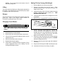
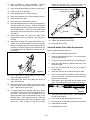
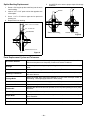
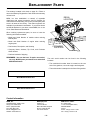
OPERATOR’S SAFETY
AND SERVICE MANUAL
F36/4
F46/4
This manual covers the following serial numbers and higher,
for each model listed:
F36/4 . . . . . . . . . . . . . . . . . . . . . 1726142
F46/4 . . . . . . . . . . . . . . . . . . . . . 1725227
WALK-BEHIND TROWELS
MBW, Inc.
MBW (UK) Ltd.
MBW France S.A.R.L
250 Hartford Rd • PO Box 440
Slinger, WI 53086-0440
Phone: (262) 644-5234
Fax: (262) 644-5169
Email: [email protected]
Website: www.mbw.com
Units 2 & 3
Cochrane Street
Bolton BL3 6BN, England
Phone: 01204 387784
Fax: 01204 387797
Z.A. d’Outreville
11 rue Jean Baptiste Néron,
60540 BORNEL
France
Phone: +33 (0) 3 44 07 15 96
Fax: +33 (0) 3 44 07 41 28
L5959 / 12.07.L
©MBW, Inc. 2007
Printed in the USA
TABLE OF CONTENTS
Safety Information . . . . . . . . . . . . . . . . . . . . . . 1
Introduction . . . . . . . . . . . . . . . . . . . . . . . . . . . . . . . . . 1
Safety Precautions . . . . . . . . . . . . . . . . . . . . . . . . . . . 1
Safety Decals . . . . . . . . . . . . . . . . . . . . . . . . . . . . . . . 1
Lubrication . . . . . . . . . . . . . . . . . . . . . . . . . . . . . . . . . 7
Lifting . . . . . . . . . . . . . . . . . . . . . . . . . . . . . . . . . . . . . 8
Storage. . . . . . . . . . . . . . . . . . . . . . . . . . . . . . . . . . . . 8
Changing Trowel Blades . . . . . . . . . . . . . . . . . . . . . . 8
Setting Tilt Arm Carriage Bolt Height . . . . . . . . . . . . . 8
Specifications. . . . . . . . . . . . . . . . . . . . . . . . . . 4
Service. . . . . . . . . . . . . . . . . . . . . . . . . . . . . . . . 9
Operation . . . . . . . . . . . . . . . . . . . . . . . . . . . . . 5
Service Tools . . . . . . . . . . . . . . . . . . . . . . . . . . . . . . . 9
Introduction . . . . . . . . . . . . . . . . . . . . . . . . . . . . . . . . . 5
Gearbox Disassembly . . . . . . . . . . . . . . . . . . . . . . . . 9
Before Starting & Operating . . . . . . . . . . . . . . . . . . . . 5
Gearbox Assembly . . . . . . . . . . . . . . . . . . . . . . . . . . . 9
Starting Engine . . . . . . . . . . . . . . . . . . . . . . . . . . . . . . 5
CFP Handle Cable/Spring Replacement . . . . . . . . . 10
Operating . . . . . . . . . . . . . . . . . . . . . . . . . . . . . . . . . . 5
Standard Handle Pitch Cable Replacement. . . . . . . 11
Blade Pitch Adjustment (Standard). . . . . . . . . . . . . . . 5
Spider Bushing Replacement. . . . . . . . . . . . . . . . . . 12
Blade Pitch Adjustment (Constant Force). . . . . . . . . . 5
Parts Replacement Cycles and Tolerances . . . . . . . 12
Handle Bar Adjustment. . . . . . . . . . . . . . . . . . . . . . . . 5
Stopping Engine . . . . . . . . . . . . . . . . . . . . . . . . . . . . . 5
Maintenance . . . . . . . . . . . . . . . . . . . . . . . . . . . 7
Replacement Parts . . . . . . . . . . . . . . . . . . . . . 13
Gearbox Assembly . . . . . . . . . . . . . . . . . . . . . . . . . . 14
Spider Assembly . . . . . . . . . . . . . . . . . . . . . . . . . . . 16
Maintenance Schedule . . . . . . . . . . . . . . . . . . . . . . . . 7
Centrifugal Clutch Drive Assembly. . . . . . . . . . . . . . 18
Fluid Levels. . . . . . . . . . . . . . . . . . . . . . . . . . . . . . . . . 7
Guard Assembly. . . . . . . . . . . . . . . . . . . . . . . . . . . . 20
Engine Maintenance . . . . . . . . . . . . . . . . . . . . . . . . . . 7
Handle Assembly . . . . . . . . . . . . . . . . . . . . . . . . . . . 22
Engine Oil . . . . . . . . . . . . . . . . . . . . . . . . . . . . . . . . . . 7
Constant Force Handle Assembly . . . . . . . . . . . . . . 24
Engine Speed . . . . . . . . . . . . . . . . . . . . . . . . . . . . . . . 7
Engine Assembly . . . . . . . . . . . . . . . . . . . . . . . . . . . 26
Cleaning . . . . . . . . . . . . . . . . . . . . . . . . . . . . . . . . . . . 7
Warranty . . . . . . . . . . . . . . . . . . . . . . . . . . . . . 28
WARNING
CALIFORNIA PROPOSITION 65 WARNING
Engine exhaust and some of its constituents are
known in the state of California to cause cancer,
birth defects, and other reproductive harm.
SAFETY INFORMATION
Introduction
SAFE DRESS: Do not wear loose clothing,
rings, wristwatches, etc. near machinery.
This Safety Alert Symbol is used to call attention
to items or operations which may be dangerous
to those operating or working with this
equipment.
The symbol can be found
throughout this manual and on the unit. Please read these
warnings and cautions, along with all decals, carefully
before attempting to operate the unit. Make sure every
individual who operates or works with this equipment is
familiar with all safety precautions.
NOISE PROTECTION: Wear OSHA specified
hearing protection devices.
EYE PROTECTION: Wear OSHA specified
eye shields, safety glasses, and sweat bands.
FOOT PROTECTION: Wear OSHA specified
steel-tipped safety shoes.
WARNING
HEAD PROTECTION: Wear OSHA specified
safety helmets.
GENERAL WARNING.
Indicates information
important to the proper operation of the
equipment. Failure to observe may result in
damage to the equipment and/or severe bodily
injury or death.
DUST PROTECTION: Wear OSHA specified
dust mask or respirator.
CAUTION
OPERATOR: Keep children and bystanders
off and away from the equipment.
GENERAL CAUTION.
Indicates information
important to the proper operation of the
equipment. Failure to observe may result in
damage to the equipment.
REFERENCES: For details on safety rules and regulations
in the United States, contact your local Occupational Safety
and Health Administration (OSHA) office. Equipment
operated in other countries must be operated and serviced
in accordance and compliance with any and all safety
requirements of that country. The publication of these
safety precautions is done for your information. MBW does
not by the publication of these precautions, imply or in any
way represent that these are the sum of all dangers present
near MBW equipment.
If you are operating MBW
equipment, it is your responsibility to insure that such
operation is in full accordance with all applicable safety
requirements and codes. All requirements of the United
States Federal Occupational Safety and Health
Administration Act must be met when operated in areas that
are under the jurisdiction of that United States Department.
Safety Precautions
LETHAL EXHAUST GAS: An internal
combustion engine discharges carbon
monoxide, a poisonous, odorless, invisible
gas. Death or serious illness may result if
inhaled. Operate only in an area with proper
ventilation.
NEVER OPERATE IN A
CONFINED AREA!
DANGEROUS FUELS: Use extreme caution
when storing, handling and using fuels, as
they are highly volatile and explosive in vapor
state. Do not add fuel while engine is running.
Stop and cool the engine before adding fuel.
DO NOT SMOKE!
Safety Decals
SAFETY GUARDS: It is the owner's
responsibility to ensure that all guards and
shields are in place and in working order.
Carefully read and follow all safety decals. Keep them in
good condition. If decals become damaged, replace as
required. If repainting the unit, replace all decals. Decals
are available from authorized MBW distributors. Order the
decal set listed on the following page(s).
IGNITION SYSTEMS: Breakerless, magneto,
and battery ignition systems can cause severe
electrical shocks. Avoid contacting these
units or their wiring.
-1-
WARNING
12265
H@
E@?@
DE@]
!"#$%
ROTATING PARTS
can crush and cut.
Keep hands away!
*
12267
12573
12573
&"'
(
')
CAUTION
&&
Read the Operating Instructions
before operating this piece of
equipment.
Keep unauthorized and untrained
people away from this
equipment.
01260
ROTATING & MOVING PARTS!
Make sure all guards and safety
devices are in place.
Wear approved hearing protection,
foot protection, eye protection and
head protection.
02355
02355
STOP
SHUT OFF the motor before servicing or cleaning.
DO NOT RUN in an enclosed area.
The engine produces carbon
monoxide, a POISONOUS GAS.
Failure to comply could result in serious
bodily injury.
13483
13483
'"'*++
+'/"$
05950
WARNING
Wh en lifting attach
proper safety chains to
hook.
Approximate weight
F46 Model s:
300 lbs. ( 136 kg)
F36 Model s:
200 lbs. ( 91 kg)
01449
02355
02355
01449
"#
#$#
01064
M-B-W INC.
'"'*++
+'/"$
05950
MADE IN U.S.A.
/"%"/<$=>?@@BD@
@E@?@D?@@GEB?HG
GHJ?L@P?=
D>QS?SVDQ@EP@HG@
Q@X&"'(
')YXYDE@VE@
@G@@?@LDE@
GJP?BB?Z@L
@=HGJL
GE@?@D?HG?L
@PG?L?L@GG?L
E@?@D"["/D?H>@Q?L
* QE@?@D
>@E@?@\DHGJ?L?P@
P?BQD?@L
+ E@@G@@>S?QED?@
HL@E
''\/@Q@G@@@LDE@VDQ@
X&"'(
')YX&&YDE@E
>QS?S
12500
13485
Safety Decals (Decal Kit #01611)
-2-
WARNING
Spring under tension!
Consult manual before
attempting service.
16167
16167
Not included
with decal kit
CONSTANT FORCE
PITCH
16168
16168
Not included
with decal kit
WARNING
CONSTANT FORCE
PITCH
Spring under tension!
Consult manual before
attempting service.
16167
Not included
with decal kit
16168
16168
Not included
with decal kit
Safety Decals - Constant Force Pitch Handle
-3-
16167
SPECIFICATIONS
F36/4
F46/4
F36/4
F46/4
F46/4HD
46 in
46 in
Gas Engines
GX160 Honda (9.9 in
GX270 Honda (16.5 in3/270cc)
6 hp Robin
7 hp Robin
GX270 Honda (16.5 in3/270cc)
GX390 Honda (23.7 in3/389cc)
7 hp Robin
GX390 Honda (23.7 in3/389cc)
Engine Speed
3400 rpm
3400 rpm
3400 rpm
Trowel Speed
70 - 135 rpm
70 - 135 rpm
70 - 135 rpm
Weight
166 lbs (74 kg) [GX160]
194 lbs (86 kg) [GX270]
165 lbs (77 kg) [6 hp]
167 lbs (84 kg) [7 hp]
230 lbs (102 kg) [GX270]
243 lbs (108 kg) [GX390]
203 lbs (100 kg) [7 hp]
293 lbs (129 kg)
Noise Level1
85 - 105 dBA
85 - 105 dBA
85 - 105 dBA
Ring Size
36 in
3/163cc)
Specifications subject to change without notice
1. Noise levels are based on operating conditions and will vary with background noise
-4-
OPERATION
Introduction
MBW equipment is intended for use in very severe
applications. They are powered by four cycle engines and
are available in different sizes and a selection of engines.
4.
Set throttle to idle.
5.
Choke engine if necessary (you may not need to
choke a warm engine).
6.
Place one hand on the trowel handle and the other on
the starter rope. Pull starter rope repeatedly until
engine starts.
This parts manual contains only standard parts. Variations
of these parts as well as other special parts are not included.
Contact your local MBW distributor for assistance in
identifying parts not included in this manual.
WARNING
NEVER place foot inside the guard ring when
starting.
Before Starting & Operating
• REMEMBER! It is the owner’s responsibility to
communicate information on the safe use and proper
operation of this unit to the operators.
• Review ALL of the Safety Precautions listed on page 1 of
this manual.
7.
Move choke lever to open position.
8.
Allow engine to warm up for one or two minutes.
Operating
1.
Increase throttle to engage the clutch.
2.
Set throttle to desired position to achieve the
appropriate trowel blade speed.
• Know how to STOP the machine in case of an
emergency.
3.
To move forward, push down on the right handle grip
and pull up on the left handle grip.
• Make sure hands, feet, and clothing are at a safe
distance from any moving parts.
4.
To move backward, pull up on the right handle grip
and push down on the left handle grip.
5.
To move left, pull up on both handle grips.
6.
To move right, push down on both handle grips.
• Familiarize yourself with the operation of the machine
and confirm that all controls function properly.
• NEW TROWELS - After assembling the handle, inspect
the throttle connections and confirm the remote throttle is
actuating the engine throttle properly and all controls
function properly.
Blade Pitch Adjustment (Standard)
• FUEL SUPPLY - The engines on MBW Power Trowels
require a good grade of unleaded automotive gasoline.
See the engine owner’s manual for specific details.
• ENGINE OIL - Check the oil level in the engine. Refer to
the Lubrication section of the engine owner’s manual.
1.
To increase the pitch, rotate the tilt knob clockwise.
2.
To decrease the
counterclockwise.
pitch,
rotate
the
tilt
knob
Blade Pitch Adjustment (Constant Force)
• GEARBOX OIL - Check the oil level in the trowel
gearbox. Refer to the Maintenance section of this
manual.
• AIR CLEANER - Check to make sure the element is in
good condition and properly installed.
1.
To increase the pitch, squeeze the trigger and pull the
lever towards you.
2.
To decrease the pitch, squeeze the trigger and push
the lever away from you.
Handle Bar Adjustment
• FUEL FILTER - Check to make sure the element is in
good condition and properly installed. Replace element
if it is clogged or damaged.
Starting Engine
1.
Loosen bolt securing the handle bar to trowel handle.
2.
Move handle bar to desired position.
3.
Tighten bolt to lock handle.
Stopping Engine
1.
Open fuel valve.
2.
Turn engine switch to “ON”.
1.
Move throttle to idle position.
3.
Turn trowel safety switch to “ON”.
2.
Turn trowel safety switch to “OFF”.
-5-
3.
Close the fuel valve.
WARNING
Always stop the engine before:
Adding fuel.
Leaving the equipment unattended for any
amount of time.
Before making any repairs or adjustments to the
machine.
-6-
MAINTENANCE
WARNING
CAUTION
Always exercise the stopping procedure before
servicing or lubricating the unit.
Always verify fluid levels and check for leaks after
changing fluids.
After servicing the unit, replace and fasten all
guards, shields, and covers to their original
positions before resuming operation.
Do not drain oil onto ground, into open streams,
or down sewage drains.
Maintenance Schedule
10 HOURS OR
DAILY
MAINTENANCE
Grease yoke plate
X
Grease spider
X
50 HOURS OR
WEEKLY
100 HOURS OR 500 HOURS OR
MONTHLY
YEARLY
Change gearbox oil
X
Check gearbox oil
X
X
Inspect drive belt
Check and tighten all hardware1
1.
X
Check all hardware after the first 5 hours of use, then follow the maintenance schedule.
Fluid Levels
SYSTEM
FLUID VOLUME
RECOMMENDED OIL
Gearbox Oil
21 oz. (620 ml)
#680 140wt Sulfer Free (MBW #05700)
Engine
Refer to engine operator/owner manual
Engine Maintenance
Engine Speed
Refer to the engine owner’s manual for maintenance
intervals and procedures.
The engine speed is factory preset according to the
Specifications section. Do not tamper with the governor
settings. The governor establishes safe operating limits.
These limits must not be exceeded.
Engine Oil
Refer to the engine owner’s manual for recommended oil
change intervals.
Cleaning
Always clean the trowel thoroughly after each day’s
operation. Dried concrete buildup can hinder performance
and shorten the life of the trowel.
WARNING
Never change the oil when engine is hot. Always
wear protective gloves when working with engine
oil.
Lubrication
To drain the oil, lift and tip the trowel forward onto the guard
ring using the trowel handle. Place a drain pan underneath
the engine and remove the drain plug. After the oil has
finished draining, reinstall the plug and clean any spilled oil
from the trowel.
-7-
1.
Grease the yoke plate and spider (see Spider
Assembly, page 16) every 10 hours or daily with a
lithium base, low temperature, general purpose lube.
2.
Change the gearbox oil once every season or 500
hours, whichever comes first. The drain/fill plug is
located on the right-hand side of the gearbox. Fill it
with 21 oz. (620 ml) of MBW Worm Gear Oil (MBW
Setting Tilt Arm Carriage Bolt Height
#05700). The oil should be to the bottom of the fill
hole when sitting level.
1.
Remove ALL the tilt arms from the spider.
Lifting
2.
The trowel should be lifted by the lifting bracket attached to
the engine. As an alternative, it may be lifted by two people
on opposite sides of the guard ring.
Remove the blades from all the arms. Wear
protective gloves when removing the blades, the
edges may be sharp
3.
Inspect the bottom side of the arms (blade mounting
surface). Remove any nicks, cement, etc... THIS
SURFACE MUST BE FLAT
4.
Loosen the jam nut and run the carriage bolt in as far
as possible.
5.
Mount the arm to gage #07277 as shown in figure 4.
Storage
The trowel should be stored with blocks supporting the outer
guard ring. Refer to the engine owner’s manual for
information regarding storage of the engine.
Changing Trowel Blades
WARNING
Trowel blade edges may be sharp when they are
worn. Wear protective gloves when handling the
blades.
Figure 4
6.
Place a .030 feeler gage between the carriage bolt
and the underside of the gage arm, and run the
carriage bolt up to just contacting the feeler gage.
There should be a slight drag felt when the feeler
gage is moved between the two surfaces.
7.
Place a 3/8” open end wrench on the square shoulder
of the carriage bolt and tighten the jam nut. DO NOT
allow the carriage bolt to turn.
1.
Set the trowel on a level surface.
2.
Remove the bolts securing the blade to the tilt arm.
3.
Lift up on the ring guard and slide the blade out from
under the tilt arm.
4.
Slide the new blade under the tilt arm.
5.
Reinstall the bolts and tighten.
8.
6.
Check that the carriage bolts are set properly. If they
require adjustment refer to the “Setting Tilt Arm
Carriage Bolt Height” section.
Recheck clearance with feeler gage and readjust if
necessary.
9.
Repeat items 5 through 8 for ALL remaining tilt arms.
10. Lubricate the tilt arm prior to fitting it in spider.
-8-
SERVICE
Service Tools
Assembly and disassembly should be performed by a
service technician who has been factory trained on MBW
equipment. The unit should be clean and free of debris.
Pressure washing before disassembly is recommended.
Part No.
• Prior to assembly, wash all parts in a suitable cleaner or
solvent.
• Check moving parts for wear and failure. Refer to the
Replacement section in this manual for tolerance and
replacement cycles.
Adjustment Tool, Tilt Arm Parallelism
07277
Adjustment Tool, Tilt Arm Height Gage
07279
Installation Tool, Spider Bushing (#06459)
16421
Bearing Spool Tool
Refer to Gearbox Assembly, page 14.
• All bearings should be replaced when rebuilding any
exciter or gearbox.
• All gaskets and seals should be replaced after any
disassembly.
1.
Remove the handle, engine, guard ring and mounting
plate (if there is one).
2.
Loosen the square head set screw (page 16, #20)
until the gearbox housing can be lifted off the spider
assembly.
3.
Flip the gearbox housing (#8) over and set it on the
four guard ring pads.
4.
Remove the yoke arm (#11) by removing one of the
retaining rings (#7), holding the pivot rod (#14) and
sliding the rod out of the holes.
5.
Remove the two flange bolts (#25) and the two flat
head screws (#26) that hold the cover (#9) to the
gearbox housing (#8).
6.
Remove the cover and discard the shims (#13) and
the o-ring (#6).
7.
Pull out the shaft (#18) with the bearings (#3) and the
worm gear (#17).
8.
Drain oil out of gearbox.
9.
Remove the four flange bolts (#24) and the bearing
cap (#20). Discard the shim gasket (#12) and the
o-ring (#23).
Torque Chart
GRADE 2
GRADE 5
49 in•lbs
76 in•lbs
56 in•lbs
87 in•lbs
8 ft•lbs
13 ft•lbs
9 ft•lbs
14 ft•lbs
15 ft•lbs
23 ft•lbs
17 ft•lbs
26 ft•lbs
24 ft•lbs
37 ft•lbs
27 ft•lbs
41 ft•lbs
37 ft•lbs
57 ft•lbs
41 ft•lbs
64 ft•lbs
53 ft•lbs
82 ft•lbs
73 ft•lbs
112 ft•lbs
83 ft•lbs
112 ft•lbs
144 ft•lbs
200 ft•lbs
188 ft•lbs
483 ft•lbs
210 ft•lbs
541 ft•lbs
652 ft•lbs
1462 ft•lbs
3 ft•lbs
4 ft•lbs
6 ft•lbs
10 ft•lbs
10 ft•lbs
20 ft•lbs
CONVERSIONS
in•lbs x 0.083 = ft•lbs
ft•lbs x 12 = in•lbs
ft•lbs x 0.1383 = kg•m
ft•lbs x 1.3558 = N•m
07276
Gearbox Disassembly
• All shafts and housings should be oiled prior to pressing
bearings. Also, ensure that the bearings are pressed
square and are seated properly.
SIZE
1/4-20
1/4-28
5/16-18
5/16-24
3/8-16
3/8-24
7/16-14
7/16-20
1/2-13
1/2-20
9/16-12
5/8-11
5/8-18
3/4-16
1-8
1-14
1-1/2-6
M6
M8
M 10
Description
GRADE 8
9 ft•lbs
10 ft•lbs
18 ft•lbs
20 ft•lbs
33 ft•lbs
37 ft•lbs
52 ft•lbs
58 ft•lbs
80 ft•lbs
90 ft•lbs
115 ft•lbs
159 ft•lbs
180 ft•lbs
315 ft•lbs
682 ft•lbs
764 ft•lbs
2371 ft•lbs
7 ft•lbs
18 ft•lbs
30 ft•lbs
10. Remove the worm shaft (#15) with the spacer (#16)
and the bearings (#4).
11. Remove the retaining cap (#10) and discard the shim
gasket (#12) and the o-ring (#23).
Gearbox Assembly
Refer to Gearbox Assembly, page 14.
-9-
1.
Lightly oil the shaft (#18). Install the key (#19) and
the retaining ring (#2) onto the shaft.
2.
With the retaining ring end of the shaft down, press
the worm gear (#17) onto the shaft. Make sure the
longer hub of the worm gear is down. The worm gear
should be pressed on the shaft until the recess in the
worm gear hub is snug against the retaining ring.
3.
Press one bearing (#3) on each end of the shaft.
Make sure the bearings are butted against the worm
gear shoulders.
17. Install the worm shaft (#15) with the bearings (#4) into
the gearbox housing. The gears must be meshed
properly.
4.
Press one bearing (#4) on each end of the worm shaft
(#15). Make sure the bearings are butted against the
worm shaft steps.
5.
If the bearing races are replaced make sure the new
races are properly seated. The bearing races in the
bottom of the gearbox housing (#8) and bearing cap
(#20) are not replaceable.
18. Install the bearing cap (#20) and apply uniform finger
pressure to the cap. Measure the gap between the
cap and gearbox housing with a feeler gage. See the
chart below for the measured gap and the shims to
use.
6.
Install a new seal (#21) into the bearing cap from the
outside. Make sure the seal is installed square and
flat.
7.
Set the worm gear and the shaft assembly into the
gearbox housing and put cover(#9) into place.
8.
Measure the gap between the cover and the gearbox
housing (apply uniform finger pressure to the center
of the cover and measure the gap with a feeler gage).
See the table below for the measured gap and what
shims to use.
Gap Measurement
9.
Gap Measurement
None
.009 - .012
(1) #05361
.013 - .018
(1) #05401
.019 - .022
(1) #05361 & (1) #05401
.001 - .008
None
.009 - .012
(1) #05359
.013 - .018
(1) #05360
.019 - .022
(1) #05359 & (1) #05360
19. Remove the bearing cap and install the proper shims
(#12).
20. Brush a light coat of oil on the o-ring groove. Roll the
o-ring (#23) over the inside lip and into the groove of
the bearing cap.
21. Poor one can (21 oz.) of #05700 oil into the worm
shaft bearing cap opening. Install the cap and secure
it with four flange bolts (#24).
Shim Gasket
.001 - .008
Shim Gasket
22. Apply a small amount of loctite #290 to the inside of
the spacer (#16) and push it on the worm shaft (#15),
through the oil seal (#21), and up against the bearing
(#4) on the inside of the gearbox housing.
Remove the cover and install the proper shims (#13).
10. Brush a light coat of oil on the o-ring groove and
inside the lip of the cover. Roll the o-ring (#6) over the
inside lip and into the groove in the cover. Install the
seal (#1) into the cover from the outside and make
sure it is installed square and flat.
CFP Handle Cable/Spring Replacement
Refer to Constant Force Handle Assembly, page 24.
1.
Remove handle assembly from machine.
2.
11. Use a piece of thin plastic over the shaft to protect the
seal and install the cover into the gearbox housing
and secure it with two flange bolts (#25) and two flat
head screws (#26).
Support handle assembly in a vise to secure for
disassembly.
3.
Loosen handle pivot bolt (#41) and fold handle
forward.
12. Rotate the shaft, there should be a little drag. If there
is too much drag another shim should be added until
a slight drag is felt. If there is sideplay in the shaft a
shim must be removed.
4.
Remove the four bolts (#32) bolts on the back of the
springbox.
5.
Carefully rotate lever (#19) arm backwards until you
feel the cable tension release. When it releases there
will be no spring tension on the lever (#19) in either
direction.
6.
Remove spring retainer bolt (#45) and end covers
(#26).
7.
Remove remaining two bolts (#33) to separate spring
box (#25) from handle.
8.
With a long needle nose pliers, disconnect the cable
from the spring.
9.
If you are only replacing spring (#28) proceed with
step 10. If you are replacing cable and/or clevis refer
to step 13.
13. Measure the main shaft run out.
Maximum
acceptable total indicator run out is .0035 inches.
14. Install the drain plug (#27) and relief valve (#22) if
removed. Use pipe sealant on the threads before
installation.
15. Brush a light coat of oil on the o-ring (#23). Roll it
over the inside lip and into the groove of the retaining
cap (#10).
16. Install two #05360 shims (#12) with the retaining cap
on the drain plug side of the gearbox housing with
four flange bolts (#24). Torque the bolts to 90in/lbs in
an “X” pattern.
- 10 -
tension on the lever arm. Rotate the lever arm
forward and release the trigger to lock the lever.
10. Note orientation of spring assembly.
Remove
bearing spool (# 29) by pushing it out either side.
11. Remove spring assembly by forcing it out either side.
ROTATE HANDLE ONCE TENSION
IS APPLIED TO CABLE
12. Refer to step 18 for assembly.
13. Push threaded portion of cable into tube.
14. Slide clevis assembly out of tube toward the bottom.
15. Remove cable from tube.
16. Route barrel end of new cable into tube.
17. Route threaded portion of the cable over the pulley on
clevis and back into the tube. Guide the threaded
end through the slot in the handle as you insert clevis
into the handle tube. Insert one of the handle bolts
through the clevis mounting holes to hold it in place.
See figure 7.
NUT
SPACER
Figure 6
18. Install spring (#28) into spring box (#25). Note
bearing spool must be removed to get spring into
housing.
19. Install bearing spool into spring with #16421 tool.
Tighten a nut on the threaded rod of the tool against
the cover of the spring box to pull the tapered pin into
the spring. Once the spring is spread, the spool can
be inserted behind the tapered pin and the tool can
be removed.
24. Install the remaining 4 bolts (#32).
25. Tighten the handle pivot bolt (#41).
26. Install handle on trowel.
Standard Handle Pitch Cable Replacement
Refer to Handle Assembly, page 22.
1.
Remove handle assembly from trowel.
2.
Remove switch assembly (#11). It is not necessary
to disconnect the wire.
3.
Turn pitch control knob all the way counterclockwise.
4.
Spiral pin (#29) should be aligned with hole on left
and slot on right.
5.
Drive pin out toward the slot just far enough to
unhook cable.
6.
Slide clevis (#5) out of the tube and remove cable.
7.
Since it is not possible to thread the cable while the
clevis is in the tube, it must be put through the pulley
with the clevis removed.
8.
Route both ends of the cable into the bottom of the
tube. The threaded end must come out of the slot.
16421
Figure 5
20. Hook cable end to spring (#28) and route cable
around activating cam (#18).
21. Install spring box side covers (#64) and secure in
place with hardware.
22. Mount spring box onto handle using center mount
point only. Align rear mounting holes but do not install
bolts. Tighten center mount bolts.
23. To engage cable pin in activating cam slot it will be
necessary to apply tension to the threaded portion of
the cable. This can be done by tightening a nut
against a spacer, such as a deepwell socket, on the
threaded end. While applying tension, rotate the
lever arm backwards until you feel the cable pin snap
into its slot. Once in place you will have constant
Figure 7
9.
Insert clevis with cable into tube. Use a handle bolt
to hold clevis in place.
10. Push cable up align eyelet with spiral pin hole.
11. Press spiral pin in flush with outside of slot on handle.
12. Install switch on handle.
13. Install handle on trowel.
- 11 -
Spider Bushing Replacement
5.
1.
Screw a 3/4-14 pipe tap about half way into the worn
outer bushing.
2.
Insert a 3/4” x 8 1/2” push rod into the opposite side
of the spider.
3.
Use a 1 1/4” x 4” tube on upper end to press old
bushing out.
4.
Repeat with inner bushing.
Use #07279 tool to ensure proper depth of bushings
as shown.
#07279
#07279
TUBE 1 1/4 I.D. X 4" LONG
3/4 - 14 PIPE TAP
Inner Bushing
6459 BUSHING
Outer Bushing
Figure 9
PUSH ROD 3/4" X 8 1/2"
Figure 8
Parts Replacement Cycles and Tolerances
Air Cleaner Element
Replace after 100 hours if the engine is operating under good clean air conditions.
Service and replace more frequently if under more severe conditions.
Bearings
Replace anytime a bearing is rough, binding, discolored or removed from housing or
shaft.
Blades
Replace when the edges become sharp or uneven. (Finish blades can be reversed)
Bushings, Trowel Arm
Replace if the trowel arm can be moved up and down more than 3/4 inch (19 mm) at
the end of the arm.
Carriage Bolts
Reset the height after trowel arm teardown or if the trowel develops chatter or
windmilling. Use height gage kit #07277 when setting.
Clutch
Replace clutch if it does not disengage below 2000 rpm.
Gaskets and Seals
Replace at every overhaul and teardown. Use MBW gasket and seal kit #05470.
Gearbox Oil
Replace after the first 50 hours of operation, then every 500 operating hours or yearly
thereafter.
Spark Plug
Change after 75 hours of operation.
Torque Bolts
Re-torque all the bolts after the first eight hours of operation and check every 25
hours thereafter.
Worm Gear
Replace if the teeth show wear marks or become sharp.
Worm Shaft
Replace if the teeth show wear marks or become sharp.
- 12 -
REPLACEMENT PARTS
The warranty is stated in this book on page 28. Failure to
return the Warranty Registration Card renders the warranty
null and void.
DECAL
LOCATION
MBW, Inc. has established a network of reputable
distributors with trained mechanics and full facilities for
maintenance and rebuilding, and to carry an adequate parts
stock in all areas of the country. Their sales engineers are
available for professional consultation. If you cannot locate
an M-B-W distributor in your area, contact MBW, Inc. or one
of our Sales Branches listed below.
When ordering replacement parts, be sure to have the
following information available:
• Model and Serial Number of machine when ordering
M-B-W parts
• Model and Serial Number of engine when ordering
engine parts
STAMPED
LOCATION
• Part Number, Description, and Quantity
• Company Name, Address, Zip Code, and Purchase
Order Number
• Preferred method of shipping
REMEMBER - You own the best! If repairs are needed,
use only M-B-W parts purchased from authorized
M-B-W distributors.
The unit’s serial number can be found in the following
locations:
• The model/serial number decal is located on the rear
side of the gearbox, next to the engine and beltguard.
• The serial number is stamped on the front of the gearbox.
Write Model Number here
Write Serial Number here
Contact Information
MBW, Inc.
MBW (UK) Ltd.
250 Hartford Rd • PO Box 440
Slinger, WI 53086-0440
Phone: (262) 644-5234
Fax: (262) 644-5169
Email: [email protected]
Website: www.mbw.com
Units 2 & 3
Cochrane Street
Bolton BL3 6BN, England
Phone: 01204 387784
Fax: 01204 387797
- 13 -
MBW France S.A.R.L
Z.A. d’Outreville
11 rue Jean Baptiste Néron,
60540 BORNEL
France
Phone: +33 (0) 3 44 07 15 96
Fax: +33 (0) 3 44 07 41 28
7
8
22
24
10
11
27
14
7
12
23
4
15
16
12
3
20
24
2
4
17
23
18
19
21
5
3
6
13
9
26
25
1
Gearbox Assembly
- 14 -
ITEM
1.
2.
3.
4.
5.
6.
7.
8.
9.
10.
11.
12.
13.
14.
15.
16.
17.
18.
19.
20.
21.
22.
23.
24.
25.
26.
27.
PART NO.
01243
01244
01251
01252
01254
01256
01279
05323
05326
05327
05329
05359
05360
05361
05401
05396
05515
05518
05521
05523
05524
05532
05533
06037
06392
F042007FWS
F051807FWS
F051808FSS
F0618SHPP
05470
05546
DESCRIPTION
SEAL, GEAR SHAFT
RETAINING RING, EXTERNAL
BEARING, TAPER ROLLER (Includes bearing and cup)
BEARING, TAPER ROLLER (includes bearing and cup)
KEY, 5/16” SQUARE x 2” LONG
O-RING
RETAINING RING, EXTERNAL
HOUSING, GEARBOX
COVER, GEARBOX
CAP, BEARING
ARM, YOKE
SHIM GASKET, 0.004”
SHIM GASKET, 0.010”
SHIM GASKET, 0.004”
SHIM GASKET, 0.010”
ROD, PIVOT
SHAFT, WORM
SPACER
GEAR, WORM
SHAFT, OUTPUT
KEY, 5/16” SQUARE x 1-11/16” LONG
CAP, BEARING
SEAL, SHAFT
VALVE, RELIEF
O-RING
FLANGE BOLT, 1/4-20 x 7/8”
FLANGE BOLT, 5/16-18 x 7/8”
FLAT HEAD SCREW, 5/16-18 x 1”
PIPE PLUG, 3/8”
REPLACEMENT KITS
KIT, GASKET & SEAL (includes 1, 12, 13, 21 & 23)
GEARBOX ASSEMBLY (includes all above items)
- 15 -
QTY
1
1
2
2
1
1
2
1
1
1
1
1
1
1
1
1
1
1
1
1
2
8
2
2
1
1
1
16
5
2
4
9
6
17
18
14
19
15
21
20
13
7
3
22
1
8
11
12
Spider Assembly
- 16 -
10
1.
2.
3.
4.
5.
6.
7.
8.
01169
01177
01258
01280
05324
05330
05331
05347
05383
05356
05397
05402
05412
05403
07935
05968
06459
06755
07850
07870
17190
F051812HCS
F05LW
F061614SHS
F0616HN
F06LW
9.
10.
11.
12.
13.
14.
15.
16.
17.
18.
19.
20.
21.
22.
01427
06199
07898
07524
DESCRIPTION
GREASE FITTING, 45
GREASE FITTING, STRAIGHT
SPRING
SOCKET HEAD SHOULDER SCREW, 3/8” x 3/8”
YOKE PLATE
PRESSURE PLATE, 4-ARM*
SPIDER, 4-ARM (includes 14)*
FINISH BLADE, 6” x 14”
FINISH BLADE, 6” x 18”
BEARING
BOLT, HOLLOW
COMBINATION BLADE, 8” x 14”
COMBINATION BLADE, 8” x 18”
FLOAT BLADE, 10” x 14”
FLOAT BLADE, 10” x 18”
CAPLUG (set of 12)
BUSHING, SPLIT
TILT ARM, 36” (includes 17 & 21)
TILT ARM, 46” (includes 17 & 21)
STABILIZER, 4-ARM*
CARRIAGE BOLT (SPECIAL), 3/8-16 x 1-1/4”
HEX HEAD CAP SCREW, 5/16-18 x 1-1/2”
LOCKWASHER, 5/16”
SQUARE HEAD SET SCREW, 3/8-16 x 1-3/4”
HEX NUT, 3/8-16
LOCKWASHER, 3/8”
REPLACEMENT KITS
GREASE FITTING CAPS (sold in sets of 12)
SPIDER & ARM ASSEMBLY, 4-ARM (includes 1, 3, 7, 10, 15, 20 & 22)
SPIDER & ARM ASSEMBLY, 4-ARM (includes 1, 3, 7, 10, 15, 20 & 22)
PRESSURE PLATE ASSEMBLY, 4-ARM (includes 5, 6 & 9)
*3-arm parts are no longer available, order 4-arm parts
- 17 -
F46/4
PART NO.
F36/4
ITEM
4
1
4
4
1
4
4
1
1
1
1
1
1
4
1
4
4
4
1
4
4
4
4
8
4
4
8
8
1
4
4
5
1
1
4
4
8
4
1
4
16
16
1
4
4
5
1
1
Centrifugal Clutch Drive Assembly
- 18 -
3.
4.
5.
6.
7.
8.
9.
10.
11.
12.
13.
14.
15.
16.
17.
06606
06618
06619
06620
06746
06858
F051806FWS
F052416HCS
F072012HCS
F062410SCS
F05LW
F07LW
F06LW
F06SW
F12SW
- 19 -
1
1
1
1
1
1
1
1
1
HONDA GX390
2.
KEY, 3/16” SQUARE x 1-5/8” LONG
KEY, 1/4” SQUARE x 1-1/2” LONG
WASHER, 5/16” SPECIAL
WASHER, 3/8” SPECIAL
V-BELT, A-27
V-BELT, A-29
V-BELT, A-30
V-BELT, A-32 (F46/4HD only)
SPACER
SPACER
SPACER
SPACER
SPACER
CLUTCH 3/4” BORE (includes 8-13 & 18)
CLUTCH 1” BORE (includes 8-13 & 18)
WEIGHT (set of 4)
SPRING
BEARING
SHEAVE
KEY, 3/16” SQUARE x 5/8” LONG
FLANGE SCREW, 5/16-18 x 3/4”
HEX HEAD CAP SCREW, 5/16-24 x 2”
HEX HEAD CAP SCREW, 7/16-20 x 1-1/2”
SOCKET HEAD CAP SCREW, 3/8-24 x 1-1/4”
LOCKWASHER, 5/16”
LOCKWASHER, 7/16”
LOCKWASHER, 3/8”
WASHER, 3/8”
WASHER, 3/4”
HONDA GX270
00032
01161
01099
06638
01289
01078
01013
07288
06340
06378
06378
06340
06378
06473
ROBIN 7 hp
1.
DESCRIPTION
ROBIN 6 hp
PART NO.
HONDA GX160
ITEM
1
1
1
1
1
1
1
1
1
1
1
1
1
1
1
1
1
1
1
1
1
1
1
1
1
1
1
1
1
1
1
1
1
1
1
1
1
1
1
1
1
1
1
1
1
1
1
1
1
1
1
1
1
1
1
1
1
1
1
1
1
1
1
1
1
1
1
1
1
1
1
3
8
8
10
9
12
12
6
7
14
4
13
15
16
17
1
18
11
5
2
Guard Assembly
- 20 -
2.
3.
4.
5.
6.
7.
8.
9.
10.
11.
12.
13.
14.
15.
16.
17.
18.
12766
GUARD RING, 36”
GUARD RING, 46”
EDGER, 36”
EDGER, 46”
BELTGUARD
BELTGUARD
PLATE, ADAPTER
PLATE, ADAPTER (F46/4HD only)
GUARD RING, EDGER, 36”
GUARD RING, EDGER, 46”
ADAPTER, 1-1/4” (F46/4HD only)
ADAPTER, 3/4” (F46/4HD only)
FLANGE SCREW, 5/16-18 x 3/4”
HEX HEAD CAP SCREW, 5/16-18 x 1-1/2” (F46/4HD
HEX HEAD CAP SCREW, 5/16-18 x 2” (F46/4HD only)
FLANGE NUT, 5/16-18
WASHER, 5/16” (F46/4HD only)
HEX HEAD CAP SCREW, 3/8-16 x 1”
FLAT HEAD SCREW, 3/8-16 x 1-1/2”
FLAT HEAD SCREW, 3/8-16 x 2-3/4” (F46/4HD only)
LOCKWASHER, 3/8”
WASHER, 3/8”
WINGNUT, 1/2-13
WASHER, 1/2”
REPLACEMENT KITS
KIT, HEAVY WEIGHT TROWEL
- 21 -
1
2
2
1
1
2
2
1
1
1
1
2
2
1
1
1
1
1
1
1
2
2
1
1
1
1
1
1
1
1
2
2
2
2
2
2
2
2
2
2
4
4
4
4
4
4
4
1
2
1
1
1
1
1
1
2
1
1
2
2
4
4
4
HONDA GX390
1
HONDA GX270
ROBIN 7 hp
05565
05575
05763
05861
07607
07825
07823
12762
07903
07904
12763
12764
F051806FWS
F051812HCS
F051816HCS
F0518FN
F05SW
F061608HCS
F061612FSS
F061622FSS
F06LW
F06SW
F0813WN
F08SW
ROBIN 9 hp
1.
DESCRIPTION
ROBIN 6 hp
PART NO.
HONDA GX160
ITEM
4
4
4
8
4
4
8
4
4
4
8
4
4
4
4
1
Handle Assembly
- 22 -
ITEM
1.
2.
3.
4.
5.
6.
7.
8.
9.
10.
11.
12.
13.
14.
15.
16.
17.
18.
19.
20.
21.
22.
23.
24.
25.
26.
27.
28.
29.
30.
31.
32.
33.
34.
PART NO.
01250
01253
01278
01302
05357
05358
05363
05365
05381
05395
05398
05477
05556
06888
07592
07662
07774
07868
07877
11742
16047
F042003FWS
F042006HCS
F0420ELN
F04LW
F04PW
F0512SP
F051805SSS
F0518ELN
F0518HN
F061622HCS
F061644HCS
F0616DLN
F06SW
07876
DESCRIPTION
GROOVE PIN
GRIP
PULLEY
THRUST BEARING
CLEVIS
KNOB
BEARING
SHAFT
CABLE
PIVOT PIN
SAFETY SWITCH ASSEMBLY
SWIVEL
ADAPTER NUT
THROTTLE ASM (includes 23, 24 & 26)
SPLICE TERMINAL
WIRE
WIRE, SHORTING (63” long)
HANDLE
CASING
HANDLE BAR
SELF TAP SCREW, 1/4-20 x 1/2
FWLS, 1/4-20 x 3/8 ZP
HHCS, 1/4-20 x 3/4 ZP
ELASTIC LOCKNUT, 1/4-20
LOCKWASHER, 1/4
WASHER, 1/4
SPIROL PIN, 5/16 x 1-1/2
SHSS, 5/16-18 x 5/8
ELASTIC LOCKNUT, 5/16-18
HEX NUT, 5/16-18
HHCS, 3/8-16 x 2-3/4 ZP
HHCS, 3/8-16 x 5-1/2 ZP
DEFORMED LOCKNUT, 3/8
WASHER, 3/8
REPLACEMENT PARTS
HANDLE ASSEMBLY (includes all above items)
- 23 -
QTY
1
2
1
1
1
1
1
1
1
1
1
1
1
1
1
1
1
1
1
1
2
1
2
2
2
2
1
1
1
1
2
1
3
6
1
2
33
13
8
14
43
41
20
21
37
24
19
42
43
35
30
15
6
22
36
32
12
17
10
16
11
7
34
42
37
18
43
30
3
31
33
1
27
43
34
40
9
23
4
39
46
44
5
38
Constant Force Handle Assembly
- 24 -
26
25
28
29
26
45
ITEM
PART NO.
1.
2.
3.
4.
5.
6.
7.
8.
9.
10.
11.
12.
13.
14.
15.
16.
17.
18.
19.
20.
21.
22.
23.
24.
25.
26.
27.
28.
29.
30.
31.
32.
33.
34.
35.
36.
37.
38.
39.
40.
41.
42.
43.
44.
45.
46.
01250
01253
01278
05357
05395
05398
05477
06888
07592
07662
07774
07877
11742
16040
16047
16075
16078
16079
16081
16083
16084
16086
16087
16099
16370
16372
16373
16374
16375
F0312SP
F042003PMS
F042004FWS
F042006HCS
F0420DLN
F0420ELN
F04LW
F04PW
F0518ELN
F0518HN
F061622HCS
F061644HCS
F0616DLN
F06SW
F08SW
F091238HCS
F0912ELN
DESCRIPTION
QTY
GROOVE PIN
GRIP
PULLEY
CLEVIS
PIVOT PIN
SAFETY SWITCH ASSEMBLY
SWIVEL
THROTTLE ASM (includes 33, 35 & 37)
SPLICE TERMINAL
THROTTLE WIRE
SHORTING WIRE ASM
CASING
HANDLE BAR
COMPRESSING SPRING
SELF TAP SCREW, 1/4-20 x 1/2
HANDLE
CLIP BEARING
CAM, ACTIVATING
LEVER ARM
LOCK DOG
TRIGGER PULL
SHAFT, ACTIVATING
CABLE
DOWEL PIN, 3/16 x 5
SPRINGBOX
COVER
CABLE CLEVIS
CONSTANT FORCE SPRING
BEARING SPOOL
SPIROL PIN, 3/6 x 1-1/2
PHMS, 1/4-20 x 3/8 ZP
FWLS, 1/4-20 x 1/2
HHCS, 1/4-20 x 3/4 GR5 ZP
DEFORMED LOCKNUT, 1/4-20
ELASTIC LOCKNUT, 1/4-20
LOCKWASHER, 1/4
WASHER, 1/4
ELASTIC LOCKNUT, 5/16-18
HEX NUT, 5/16-18
HHCS, 3/8-16 x 2-3/4 GR5 ZP
HHCS, 3/8-16 x 5-1/2 GR5 ZP
DEFORMED LOCKNUT, 3/8
WASHER, 3/8
WASHER
HHCS, 9/16-12 x 4-3/4 GR5 ZP
ELASTIC LOCKNUT, 9/16-12
1
2
1
1
1
1
1
1
1
1
1
1
1
1
2
1
2
1
1
1
1
1
1
1
1
2
1
1
1
3
2
4
4
4
2
2
4
1
1
2
1
3
6
2
1
1
REPLACEMENT PARTS
16080
16092
16367
LEVER ARM ASSEMBLY (includes 14, 19-21 & 24)
HANDLE ASSEMBLY (includes all above items)
SPRING SPOOL ASSEMBLY (includes 27-29, 31 & 34)
- 25 -
1
1
1
HONDA GX160, ROBIN 6hp & ROBIN 7hp
HONDA GX270, GX390 & ROBIN 9hp
Engine Assembly
- 26 -
ITEM
1.
2.
3.
4.
5.
6.
7.
8.
9.
10.
11.
12.
13.
14.
PART NO.
01444
17370
17371
17440
15674
12887
07636
19372
19370
F0203HTB
F051814HCS
F0518FN
F052406HCS
F05LW
F05SW
F061608FWS
F061614HCS
F061624HCS
F0616FN
F06SW
Q2893881
Q5266721
Q2893907
DESCRIPTION
ENGINE, HONDA GX160
ENGINE, ROBIN EX17 6hp
ENGINE, ROBIN EX21 7hp
ENGINE, ROBIN EX27 9hp
ENGINE, HONDA GX270
ENGINE, HONDA GX390
DEFLECTOR, EXHAUST
LIFTHOOK, PLATED, TROWEL (For engines 9-13 hp)
LIFTHOOK, PLATED, TROWEL (For engines 5-7 hp)
HEX TAP BOLT, #8 x 3/8
HHCS, 5/16-18 x 1-3/4
FWLS, 5/16-18
HHCS, 5/16-24 x 3/4
LOCKWASHER, 5/16
WASHER, 5/16
FWLS, 3/8-16 x 1
HHCS, 3/8-16 x 1-3/4
HHCS, 3/8-16 x 3 (F46/4HD only)
FLANGE NUT, 3/8-16
WASHER, 3/8
REPLACEMENT KITS
AIR FILTER, GX160 HONDA ENGINE
AIR FILTER, GX270 HONDA ENGINE
AIR FILTER, GX390 HONDA ENGINE
- 27 -
QTY
1
1
1
1
1
1
1
1
1
2
4
4
4
4
4
4
4
4
4
4
WARRANTY
WHAT DOES THIS WARRANTY COVER? MBW, Incorporated (MBW)
warrants each New Machine against defects in material and workmanship
for a period of twelve (12) months. "New Machine" means a machine
shipped directly from MBW or authorized MBW dealer to the end user. This
warranty commences on the first day the machine is sold, assigned to a
rental fleet, or otherwise put to first use.
batteries, and the like, all of which are sold AS IS/WHERE IS WITH ALL
FAULTS.
MBW warrants each Demonstration Machine against defects in material
and workmanship for a period of six (6) months. "Demonstration Machine"
means a machine used by MBW or its agents for promotional purposes.
This warranty commences on the first day the machine is sold, assigned to
a rental fleet, or otherwise put to first use.
6.This warranty does not cover any updates to any New Machine,
Demonstration Machine, or any other MBW product. MBW reserves the
right to improve or make product changes without incurring any obligation
to update, refit, or install the same on New Machines or Demonstration
Machines previously sold.
This warranty covers the labor cost for replacement or repair of parts,
components, or equipment on New Machines or Demonstration Machines,
and MBW shall pay labor costs at MBW's prevailing rate to affect the
warranted repair or replacement. MBW reserves the right to adjust labor
claims on a claim-by-claim basis.
WHAT MUST YOU DO TO OBTAIN WARRANTY COVERAGE? Each
New Machine or Demonstration Machine is accompanied by a Warranty
Registration Card. You must sign, date, and return the Warranty
Registration Card to the place of origin of the New Machine or
Demonstration Machine, either to MBW, Inc. at P.O. Box 440, Slinger,
Wisconsin 53086, MBW (UK), Ltd. at Units 2 & 3 Cochrane Street, Bolton
BL3 6BN, United Kingdom or MBW FRANCE SARL at
ZA D'Outreville, 5 Rue Jean Baptiste Neron, Bornel 60540 France, within
ten (10) days after purchase, assignment to a rental fleet, or first use. This
signed warranty card is the buyer's affirmation that he has read,
understood, and accepted the warranty at the time of purchase. Failure to
return the warranty card as specified herein renders the warranty null and
void. In order to receive warranty coverage consideration, warranty claims
must be submitted within thirty (30) days after the New Machine or
Demonstration Machine fails. Warranty claims must be submitted to MBW,
Inc., MBW (UK), Ltd. or MBW FRANCE SARL, and written authorization for
the return of merchandise or parts under the warranty must be obtained
before shipment to MBW.
This warranty covers the shipping cost of replacement parts, components,
or equipment via common ground carriers from MBW to an authorized
MBW dealer. Air freight is considered only in cases where ground
transportation is not practical.
MAY THIS WARRANTY BE TRANSFERRED? This warranty is nontransferable and only applies to the original end user of a new machine or
demonstration machine.
WHAT DOES THIS WARRANTY NOT COVER?
1.This warranty does not cover any Used Equipment. "Used Equipment"
means any MBW machine or equipment that is not a New Machine or a
Demonstration Machine. All Used Equipment is sold AS IS/WHERE IS
WITH ALL FAULTS.
2.This warranty does not cover any New Machine, Demonstration
Machine, or their equipment, parts, or components altered or modified in
any way without MBW's prior written consent. This warranty does not
cover the use of parts not specifically approved by MBW for use on MBW
products. This warranty does not cover misuse, neglect, shipping damage,
accidents, acts of God, the operation of any New Machine or
Demonstration Machine in any way other than recommended by MBW in
accordance with its specifications, or any other circumstances beyond
MBW's control. This warranty does not cover any New Machine or
Demonstration Machine repaired by anyone other than MBW factory
branches or authorized MBW distributors.
3.This warranty does not cover, and MBW affirmatively disclaims, liability
for any damage or injury resulting directly or indirectly from design,
materials, or operation of a New Machine or Demonstration Machine or any
other MBW product. MBW's liability with respect to any breach of warranty
shall be limited to the provisions of this document and in no event shall
exceed an amount equal to the purchase price of the New Machine or
Demonstration Machine purchased from MBW.
4.This warranty does not cover engines, motors, and other assemblies or
components produced by other manufacturers and used on a New
Machine or Demonstration Machine, as said engines, motors, and other
assemblies or components may have warranties provided by the
manufacturer thereof. This warranty does not apply to consumable items,
such as v-belts, filters, trowel and screed blades, seals, shock mounts,
5.This warranty does not cover the cost of transportation and other
expenses which may be connected with warranty service but not
specifically mentioned herein.
WHAT WILL MBW DO? MBW's obligation under this warranty is limited to
the replacement or repair of parts for a New Machine or Demonstration
Machine at MBW factory branches or at authorized MBW distributors, and
such replacement or repair is the exclusive remedy provided hereunder.
Labor must be performed at an authorized MBW distributor. MBW
reserves the right to inspect and render a final decision on each warranty
case, and MBW's repair or replacement is solely within the discretion of
MBW.
IT IS EXPRESSLY AGREED THAT THIS SHALL BE THE SOLE AND
EXCLUSIVE REMEDY UNDER THIS WARRANTY. UNDER NO
CIRCUMSTANCES SHALL MBW BE LIABLE FOR ANY COSTS, LOSS,
EXPENSE, DAMAGES, SPECIAL DAMAGES, INCIDENTAL DAMAGES,
OR PUNITIVE DAMAGES ARISING DIRECTLY OR INDIRECTLY FROM
THE USE OF THE NEW MACHINE OR DEMONSTRATION MACHINE
WHETHER BASED UPON WARRANTY, CONTRACT, NEGLIGENCE,
STRICT LIABILITY, OR ANY OTHER LEGAL THEORY.
THE FOREGOING WARRANTY IS EXPRESSLY IN LIEU OF ALL
OTHER WARRANTIES, EXPRESS OR IMPLIED, INCLUDING THE
WARRANTIES OF MERCHANTABILITY, FITNESS FOR USE, AND
FITNESS FOR A PARTICULAR PURPOSE, AND ALL OTHER
OBLIGATIONS OR LIABILITY ON MBW'S PART. MBW NEITHER
ASSUMES NOR AUTHORIZES ANY OTHER PERSON TO ASSUME ON
BEHALF OF MBW ANY OTHER LIABILITY OR WARRANTY IN
CONNECTION WITH THE SALE OR SERVICE OF ANY NEW MACHINE,
DEMONSTRATION MACHINE , OR ANY OTHER MBW PRODUCT.
- 28 -
NOTES
- 29 -
NOTES
- 30 -