1
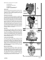
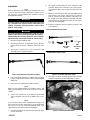
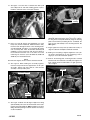
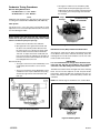
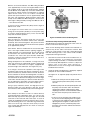
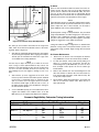
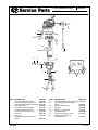
INSTRUCTIONS
®
REV. 8-31-01
-J01839
Kit Numbers 27970-00, 27937-00, 28009-00 and 28011-00
SCREAMIN' EAGLE® PERFORMANCE INDUCTION SYSTEM
General
Kit Contents cont.
This kit is designed for use on 1999 and later Carbureted
Twin Cam 88 and 1993 and later 1340 Evolution Model
Motorcycles.
CAUTION
Harley-Davidson® motorcycles equipped with some
Screamin’ Eagle® high-performance engine parts may
not be used on public roads and in some cases must be
restricted to closed course competition. This engine
related performance part is intended for racing applications and is not legal for sale or use in California on pollution controlled motor vehicles. Engine related performance parts are intended FOR THE EXPERIENCED
RIDER ONLY.
NOTE
S.E. Holley Carburetor Rebuild Kit (P/N 29680-00) and
Carburetor Performance Tuning Kit (P/N 29681-00B) are
also available from your authorized Harley-Davidson Dealer.
Kit Contents
This kit consists of the following parts. Some parts are
unique to EVO applications (Kit Numbers 27970-00 and
28009-00) and some are unique to Twin Cam applications
(Kit Numbers 27973-00 and 28011-00). For detailed carburetor internal parts listing, see Service Parts Illustration on
Page x.
Qty
3
1
1
1
1
2
2
1
1
2
1
1
1
1
1
1
1
1
3
1
1
1
1
1
Description
Bolts, carb to manifold,
5/16x1-1/4 inch
Valve, enrichener
Guide, enrichener cable
Bracket, throttle cable
Screw, throttle cable bracket
Jet, main size #58
Jet, main size #62
Cable, choke
Fuel hose
Seal, intake manifold
Flange, intake front
Flange, intake rear
Intake manifold, Evolution
Intake manifold, Twin Cam
Gasket, carburetor to manifold
Carburetor (satin)
Carburetor (polished)
Hose, breather
Stud
Back plate, air cleaner
Filter element (Evo kit only)
Filter element (Twin Cam Kit only)
Gasket, back plate to manifold
Breather, manifold
Part Number
29711-00
29723-00
29724-00
29725-00
29726-00
29731-00
29733-00
29719-00
63631-00
26995-86B
27009-86A
27010-86A
29003-00
29677-00
27972-00
27971-00
28010-00
63534-90
29447-99
29129-00
29675-00
29679-00
29676-00
27900-97
Qty
4
3
2
2
1
2
*
2
2
1
1
1
Description
Part Number
Clamp, worm drive 3/8 inch
9946
Screw, button head 1/4-20x1/2 inch 4365
Screw, flat head 1/4-20x5/8 inch
3793A
Seal, manifold
26995-86B
Nipple, 90 degree
63707-00
Washer
46465-99
Washer (6 w/Evo kit), (4 w/TC kit) 45596-93
Banjo bolt (Evo kit only)
45571-97A
Banjo bolt (Twin Cam kit only)
45507-99
Bracket, mounting
29133-00
Insert, air cleaner (Evo only)
29448-99
Insert, air cleaner (Twin Cam only) 29450-99
Screamin’ Eagle/Holley Carb Overview
The Screamin’ Eagle/Holley Carburetor is a two-barrel carburetor for your Evolution or Twin Cam powered HarleyDavidson. It can be calibrated for all engine configurations.
The charts and tuning instructions in this Instruction Sheet
will aid in the calibration process.
The carburetor has three main components:
The Fuel Bowl,
The Metering Block,
The Mainbody.
See Figure 1. The fuel bowl is a fuel reservoir to provide fuel
to the different circuits of the carburetor. The metering block
is a mixing and delivery service. The mainbody is the inlet for
air and the outlet for fuel and air.
Figure 1. Three Main Components of Carburetor
1 of 11
Within the three components are five systems:
The Float System
The Accelerator Pump System
The Idle Circuit
The Transfer or Slow Speed Circuit
The Main or High Speed Circuit
Idle
Circuit
Float System
The Float System located in the fuel bowl is critical for all circuits of the carburetor. It regulates the amount of fuel in the
fuel bowl that will be available to the different circuits of the
carburetor. If set to low, all circuits will run lean. If set too
high, all circuits will run rich.
Accelerator Pump System
The Accelerator Pump System provides the carburetor with
extra fuel to aid in acceleration, letting the carburetor smoothly transition from idle to off idle to the main circuit when the
bike is accelerated. The amount of fuel fed by the accelerator
pump system is controlled by the size of the discharge holes
in the accelerator pump discharge nozzle. The accelerator
pump discharge nozzle is located in the mainbody. Refer to
Figure 1. A pump circuit with too small of an accelerator
pump discharge nozzle hole size will cause the bike to hesitate and possibly backfire from the carburetor. Too large of
an accelerator pump discharge nozzle hole size and the bike
will be lazy during acceleration with black smoke being emitted from the tailpipe. A correctly sized pump discharge nozzle will give crisp, clean accelerations.
Idle Circuit
The Idle Circuit is used to deliver a mixture of fuel and air to
the engine during idle. It will only work for a very short time
off idle before stopping and letting the transfer circuit takeover. The fuel air mixture is adjusted by the idle mixture
screws (in the metering block) and metered by the idle fee
restrictions (in the mainbody). Figures 2 and 3. Setting(s) that
are too rich give poor idle quality and black smoke out of the
exhaust. Settings that are too lean give poor idle quality with
hesitations during accelerations.
Transfer Circuit (Slow Speed)
The Transfer Circuit is used to deliver a mixture of fuel and
air to the engine during off idle and cruise range. Its fuel is
metered by two restrictions in the mainbody that deliver fuel
to the transfer slot located in the throttle bore of the mainbody. See Figure 3. Calibrating too lean will result in poor drivability in the cruise range with spitting out of the carburetor.
Calibrating too rich will result in poor drivability in the cruise
range with popping out the exhaust and a possible engine
miss at cruise speeds.
Figure 2. Idle Circuit and Accelerator Pump System
Transfer or
Slow Speed
Circuit
Main or
High Speed
Circuit
Main Circuit (High Speed)
The Main Circuit is used to deliver a mixture of fuel and air to
the engine during high rpm usage. Fuel for the main circuit is
drawn through the main metering jets (See Figure 4) and discharged through the booster venturi’s. Whether the main circuit is rich or lean will result in a loss of power. The main circuit is best tested at the track or on a dynamometer but can
be calibrated by “feel” while driving the bike. A main circuit
that is too rich or too lean will make the motorcycle feel lazy.
Let plug readings tell you if it is too rich or too lean.
Figure 3. Metering Block and Fuel Bowl (Metering Jets)
-J01839
2 of 11
Installation
NOTE
Refer to applicable Service Manual for detailed instructions
on how to remove necessary components in order to access
the carburetor. Service Manuals are available from your
Harley-Davidson Dealer.
1WARNING
To protect against shock and accidental start-up of vehicle, disconnect the negative battery cable before proceeding. Inadequate safety precautions could result in
death or serious injury.
1WARNING
8.
See Figure 5. Disassemble the stock enrichener cable
assembly. Remove the enrichener valve, spring, plastic
nut, 90 degree elbow, hex nut and star washer from the
cable.
9.
Obtain the new enrichener cable (P/N 29719-00) from kit
and install the star washer and hex nut just removed
from the existing assembly. Install the rubber boot over
the straight steel cable guide (P/N 29724-00). Install the
original plastic nut and spring along with the new enrichener valve (P/N 29723-00).
10. Install the enrichener cable assembly to the back of the
new carburetor.
Disassembled Enrichener Cable
Always disconnect the negative battery cable first. If the
positive cable should contact ground with the negative
cable installed, the resulting sparks may cause a battery
explosion which could result in death or serious injury.
1.
Disconnect negative battery cable.
2.
Following instructions in applicable Service Manual,
remove stock air cleaner, carburetor and intake manifold.
3.
See Figure 4. Remove the stock enrichener cable
assembly from the original carburetor.
Figure 4. Stock Enrichener Cable Assembly
4.
If the stock intake manifold has a MAP sensor installed,
remove it and install it into the intake manifold supplied
with the kit.
5.
Install new seals and flanges to intake manifold.
New Cable
Guide
New
Enrichener
Valve
Assembled Enrichener Cable
Figure 5. Assemble Enrichener Cable
11. See Figure 6. Obtain manifold gasket (P/N 27972-00)
and position between manifold and gasket as shown.
NOTE
Make sure the manifold flanges are installed correctly. The
flanges are designated “F” for the front and “R” for the rear
cylinder.
6.
Connect the vacuum hose to the fitting on the manifold
and the electrical connector to the MAP sensor, if present.
NOTE
If your fuel petcock has been changed and no longer uses
the vacuum line from the original petcock to the intake manifold, the port on the top of the new manifold needs to be
capped and the vacuum line needs to be plugged.
7.
Install the manifold to the cylinder heads and finger tighten only at this time.
-J01839
Figure 6. Position Manifold Gasket
3 of 11
12. See Figure 7. Use the three 1-1/4X5/16 inch bolts (P/N
29711-00) from kit and while holding gasket in place,
install the carburetor to the new intake manifold.
90 degree
Fitting
Figure 9. Install Hose Fitting to Backplate
Figure 7. Install Carburetor
13. Place one large ID washer (P/N 45596-93) over each
banjo bolt (TC-P/N 45507-99, EVO-P/N 45571-97A).
Insert the bolts through the holes in the mounting bracket (P/N 29133-00), then place a second large ID washer
over each banjo bolt. Place the breather manifold (P/N
27900-97) over the banjo bolts with the hose fitting on
the manifold toward the rear of the bike. Place the
remaining two washers (TC-P/N 46465-99, EVO-P/N
45596-93) over the breather bolts.
NOTE
On Twin Cam engines, the last washers will have small ID.
14. See Figure 8. While holding the assembly together,
insert the banjo bolts into the tapped holes in the cylinder heads. Tighten each bolt a little at a time until the
assembly is loosely held in place.
16. See Figure 10. Install the backing plate gasket (P/N
29676-00) and backing plate to the front of the carburetor using three studs (P/N 26447-99). Align the backing
plate to the bracket by installing the two 1/4-20x5/8” flat
head screws (P/N 3793A) to the mounting bracket. Do
NOT tighten.
17. Finger tighten the banjo bolts (installed into heads) to
align the carburetor backplate and intake manifold.
18. Making sure everything is aligned, tighten the rear cylinder intake manifold bolts on left (sparkplug) side of
engine) to secure the manifold in position.
19. Remove the backing plate, mounting bracket, manifold
breather tube and carburetor assembly then tighten the
front cylinder intake manifold bolts on right (pushrod)
side of engine.
Screws
Manifold Breather
Banjo Bolt
Studs
Mounting
Bracket
Figure 10. Install Backing Plate
Figure 8. Install Mounting Bracket Assembly
15. See Figure 9. Obtain the 90 degree nipple hose fitting
(P/N 63707-00) and screw into the backside of the backing plate (P/N 29129-00). Do NOT overtighten. The hose
fitting should be pointing toward the back of the motorcycle after installation.
-J01839
4 of 11
20. See Figure 11. Route and connect the throttle cables to
the carburetor throttle wheel.
1WARNING
Refer to the applicable Service Manual and ensure that
the throttle cables are of the correct length and are routed correctly. If the cables are not of the correct length or
routed correctly, they could interfere with the operation
of the motorcycle. This could cause loss of control of
vehicle which could result in death or serious injury.
Bracket
Bracket
Screw
Figure 13. Install Bracket to Carburetor
23. See Figure 14. Reinstall the intake manifold gasket and
carburetor to the intake manifold using three 5/16x1-1/4
inch bolts (P/N 29711-00). Tighten to 10-12 ft-lbs (13.616.3 Nm).
Figure 11. Connect Throttle Cables To Throttle Wheel
21. See Figure 12. Obtain the new throttle cable bracket
(P/N 29725-00) and bracket screw (P/N 29726-00), and
install the throttle cables into the bracket.
Throttle Cable
Bracket
Figure 14. Reinstall Intake Manifold Gasket and
Carburetor to Manifold
1WARNING
Figure 12. Install Throttle Cables to Bracket
22. See Figure 13. Install bracket onto carburetor and torque
screw to 3-5 ft-lbs (4.1-6.8 Nm).
Refer to the applicable Service Manual and ensure that
throttle cables are of the correct length and are routed
correctly. If the cables are not of the correct length or
routed correctly, they could interfere with the operation
of the motorcycle. This could cause loss of control of
vehicle which could result in death or serious injury.
24. The throttle control must operate freely without binding.
With the friction adjusting screw backed off, the carburetor throttle must return to the closed (idle) position.
Perform Steps a through c to adjust the throttle cables.
CAUTION
The throttle cable adjustment is necessary to prevent
excess stress and potential failure to the throttle cables.
-J01839
5 of 11
NOTE
The throttle cable has a 5/16x18 inch threaded adjuster and
is assembled to the right side of the throttle grip. The idle
cable has a 1/4x20 inch threaded adjuster and is assembled
to the left side of the throttle grip.
a.
Turn the cable adjusters and locknuts clockwise as
far as they will go. Both cables should have zero
adjustment to start this procedure.
b.
See Figure 15. Point the front wheel straight ahead.
Turn the throttle grip so throttle is wide open (fully
counter-clockwise) and hold it there. Now turn the
throttle cable adjuster (1) counter-clockwise until the
throttle cam stop just touches the stop boss on the
carburetor. Tighten the locknut (2) against the throttle cable adjuster and release the throttle.
c.
29. Refer to Figure 6. Reinstall the carburetor-to-backing
plate gasket and backing plate to carburetor and mounting bracket using two flat head screws (P/N 3793A) and
three 1/4-20 studs (P/N 29447-99). Tighten all five fasteners 3-5 ft-lbs (4.1-6.8 Nm).
30. Tighten the manifold breather tube banjo bolts to 10-12
ft-lbs (13.6-16.3 Nm).
NOTE
It may be necessary to shorten the “short end” of your allen
wrench to tighten the bolts.
31. See Figure 16. Attach the short end of the manifold
breather hose to the 90 degree fitting on the backside of
the backing plate and secure with 3/8” hose clamp (P/N
9946).
Turn the front wheel full right. Turn the idle cable
adjuster counter-clockwise until the idle cable housing just touches the spring in the cable support
sleeve. Work the throttle grip to make sure throttle
cable returns to idle position when released. If the
cable does not return to idle, turn the cable adjuster
clockwise to achieve the correct adjustment.
Tighten the idle cable adjuster locknut against the
idle cable adjuster. Check adjustment by turning
forks to full left, full right lock, and straight ahead.
Figure 16. Install Breather Hose to Backing Plate
32. See Figure 17. Cut the long end of the manifold breather
hose to the correct length, connect it to the manifold
breather and secure with 3/8” hose clamp (P/N 9946).
Figure 15. Throttle Cable Adjustment
(1995 Switch Housings Shown)
25. Check carburetor for correct throttle opening and closing. Correct any existing problems at this point before
proceeding.
26. Obtain fuel hose (P/N 63631-00) from kit and install one
end on the carburetor fuel bowl inlet. Secure end with
3/8” hose clamp (P/N 9946).
27. Route fuel hose through its original position using the
original protective sleeves. Attach the end to the fuel
supply valve and secure using 3/8” hose clamp (P/N
9946).
28. Apply a small amount of Loctite 243 (blue) to the banjo
bolts and reinstall the manifold breather tube, bracket
and banjo bolt assembly to the cylinder heads.
-J01839
Figure 17. Install Breather Hose to Manifold
33. See Figure 18. Install the air filter (TC-P/N 29679-99 or
EVO P/N 29675-00) to the backing plate and secure
with three button head screws (P/N 4365). Tighten to 35 ft-lbs (4.1-6.8 Nm).
6 of 11
Check Enrichener Adjustment
NOTE
Check enrichener operation. The fuel enrichener knob should
open, remain open, then close without binding. The knurled
plastic nut next to the enrichener knob controls the ease or
difficulty with which the cable slides within the cable conduit.
If adjustment is needed perform Steps a through e. as follows:
a.
Loosen hex nut at backside of mounting bracket.
b.
Move cable assembly free of slot in mounting bracket.
c.
Hold cable assembly at flats with adjustable wrench.
Turn knurled plastic nut counter-clockwise by hand,
to reduce sliding resistance until knob slides inward
unaided.
d.
Turn plastic nut clockwise to increase sliding resistance until knob remains fully out without holding
and closes with relative ease.
e.
Position cable assembly in slot in bracket. Tighten
hex nut at backside of bracket.
Figure 18. Install Air Filter
34. See Figure 19. Apply Loctite 243 (blue) to threads of
cover screw removed from original air cleaner and install
cover using screw and washer.
CAUTION
Do not lubricate the cable or inside of conduit. The cable
must have sliding resistance to operate properly.
36. Recheck throttle cable operation.
1WARNING
Always connect the positive battery cable first. If the positive cable should contact ground with the negative cable
installed, the resulting sparks may cause a battery explosion resulting in death or serious injury.
Figure 19. Install Air Cleaner Cover
35. Secure the enrichener cable to its bracket on the left
side of the motorcycle.
37. Connect the battery cables, positive cable first.
38. Start the motorcycle per procedure outlined in your
Owners Manual or applicable Service Manual. Once
engine is warm, set idle speed set screw according to
Manual specifications, usually 1000 RPM.
NOTE
If original petcock is still being used, it may take several seconds for enough fuel to enter the fuel bowl to start the motorcycle.
39. Drive the motorcycle and check engine performance. If
engine performance is unsatisfactory, tune the carburetor following instructions under Carburetor Tuning
Procedures in these instructions.
-J01839
7 of 11
Carburetor Tuning Procedures:
General Jetting Nomenclature
Fuel Restrictors are called “Feeds”.
Air Restrictors are called “Bleeds”.
NOTE
Additional main metering jets and transfer feed restrictions
for tuning are included in the TUNERS KIT (P/N 29681-00).
c. See Figure 21. Make sure to reinstall the pump
check needle into the pump passage of the fuel
bowl before the bowl is installed. The pointed end
of the needle goes in the passage first. Reinstall
the fuel bowl.
Pump
Passage
Accelerator Pump
Check Needle
Float System
The Float Level is set at the factory and should not need
adjustment. In the event that adjustment becomes necessary
use the following procedure.
Fuel
Bowl
CAUTION
When removing the fuel bowl from the carburetor, be
careful not to drop the accelerator pump check needle
from the accelerator pump fuel passage.
a. Remove the fuel bowl from the carburetor.
b. See Figure 20. Press against the float tab until
the float is in its full UP position. Measure from
the outer end or “toe” of the float to the top edge
of the fuel bowl. This measurement should be
.475 inch. To adjust, loosen the needle and seat
lock screw and turn the adjusting nut clockwise to
lower the level and counter-clockwise to raise the
level. Retighten the lock screw.
Note the following:
* Too high of a float level can be identified by a loss
of idle quality when the bike is set on its kick
stand.
* Too low of a float level can be identified by a lean
condition that can only be calibrated out by using
excessively large transfer feed restrictions and
main jets.
Figure 21. Float Bowl
Idle Mixture Screws (IMS) and Idle Feed Restrictions
See Figure 22. There are two brass feed restrictions located
on the bottom surface of the carburetor main body, above the
metering block. The idle feed restrictions are the two outer
feeds, located on this surface.
IMPORTANT
It is not recommended to change these idle feed restrictions from the .022 that are installed in the as-received
carburetor, since IMS setting will have the same effect.
The IMS are located in the left and right sides of the metering
block, and are fuel flow adjusters for idle and part throttle
load ranges. Turning the IMS “IN” (clockwise) leans the carburetor and turning it “OUT” (counterclockwise) enriches the
carburetor.
NOTE: The normal range for the IMS is 1/2 to 3 turns “OUT”.
Figure 20. Float Adjustment
Figure 22. Metering Block
-J01839
8 of 11
With the as-received carburetor, the IMS setting should be
set to approximately 1 turn out. If the engine exhibits a rich or
lean condition at idle or up to 3/8 throttle opening, adjusting
the Idle Mixture Screw (IMS) may correct the condition without having to change transfer feed restrictions. If required,
adjust the two screws, in or out, to obtain a steady idle
speed. Idle speed should be reset to approximately 1000
rpm, after each adjustment. Slight hesitations right off idle
usually can be attributed to IMS setting that is too lean even
if the engine is idling smoothly. Turning each IMS out 1/8th to
....turn should correct this.
If you have access to Air/Fuel ratio (AFR) sensors, target an
AFR of 13.0:1 at idle.
If the engine runs well at either 1/2 or 3 turns extreme,
change to one step leaner (smaller) or one step richer (larger) Transfer Feed Restrictions (TF’s). Then, reset the IMS
away from the extreme positions.
Transfer Feeds (TF)Refer to Figure 22. The transfer feeds (TF) are the slow
speed jets located on the bottom surface of the carburetor
main body, above the metering block. They are the two inner
feeds. The Transfer Feeds affect off idle and cruise operation
up to approximately 70 mph.
Start with the .022 TF’s installed into the as-received carburetor. If the engine exhibits leanness (spitting, sluggish), at
off-idle transients or at cruising speeds, the TF’s will need to
be increased in size. Sizes from .024”, .026”, and .028” are
included in the Tuners Kit (Part Number 29681-00).
Increases in transfer feed restriction size may allow for a
smaller main jet and vice-versa.
Figure 23. Bottom Surface of Metering Plate
Accelerator Pump Discharge Nozzle (PD Nozzle)
The PD Nozzle is located in the lower front center of the carburetor air inlet. Refer back to Figure 1.
There are two discharge holes located on the backside, oriented so they hit the sides of the booster venturis. With
engine off, rotate throttle to verify fuel is being discharged
from both discharge holes. If not, remove nozzle and blow
compressed air through each hole.
1.
Start with the .016 inch PD nozzle installed in the asreceived carburetor. If you experience slow throttle
response during acceleration, or a hesitation that cannot
be removed by IMS adjustment, or there is a dip in the
torque curve at low rpm’s when running on a
dynamometer, increase to the larger .018” PD Nozzle,
included in the Tuners Kit.
2.
Check the pump rod adjustment. A improperly adjusted
pump rod can cause off-idle hesitations.
During development of this carburetor, no larger TF’s than
.024” were found to be required with engines ranging from
stock EVO’s to 1550 Twin Cam engines, equipped with
Screamin” Eagle cams and heads. Your engine may vary.
If no change is noted in the operation of the engine after
changing to larger Feeds, there may be restrictions in the circuits. To check for any restriction in these circuits, disassemble the carburetor to remove the metering block. Located on
the bottom surface of the metering plate are five brass tubes
that extend into the float bowl. See Figure 23. The two larger
center tubes hold the main jets, while the smaller back ones
are the idle/transfer feed tubes. The fifth smaller tube inbetween the main jet tubes is for the choke fuel pick-up.
Using a spray carburetor cleaner, and high-pressure air,
flush these tubes out, in the direction of fuel flow, from the
end of the brass tube toward the body of the metering block.
NOTE
Don’t attempt to flush these circuits in a reverse direction,
from metering block toward brass tubes. You can force any
debris that may be present in these passages, into the small
restrictions at the float bowl end of the tubes. To assist in
seeing any small debris that may be present in these circuits,
place the metering block on a clean white rag and flush the
tubes out on to this rag. It may also be necessary to use the
spray cleaner and high-pressure air to flush out each passage in the mainbody.
-J01839
See Figure 24. To adjust the pump rod, perform the following.:
a. Remove the cotter pin from the pump rod and
remove the pump rod from the pump cover exten
sion arm.
b. With the pump rod in the full upward position and
the pump cover extension arm in the full down
ward position (without compressing the pump
diaphragm) half of the rod end should be visible in
the lower half of the pump cover extension arm
hole.
c. If more or less of the pump rod is visible, loosen
the jam nut and turn adjusting barrel to lengthen
or shorten the rod. Retighten the jam nut and turn
adjusting barrel to lengthen or shorten the rod.
Retighten the jam nut, reinstall the pump rod in
the pump cover extension armhole and reinstall
the cotter pin.
9 of 11
Adjusting
Barrel
Jam
Nut
Figure 24. Accelerator Pump Rod Adjustment
Main Jets
The main jets are located at the bottom of the large brass
tubes, which are located on the bottom surface of the metering block. Refer to Figure 23.
1.
Start with the suggested jetting listed in the chart (Figure
25) and change as required. Sizes ranging from 56 up to
70 main jets are included in the Tuners Kit. Larger sizes
are available from a Holley distributor.
NOTE
The best way to adjust the main jets is either on the racetrack or using a chassis dynomometer but they can be calibrated by “feel” while driving the bike. A main system that is
too rich or too lean will make the motorcycle feel lazy. Let
plug readings tell you if the engine is running too rich or too
lean.
2.
3
Start with the jet sizes suggested in the chart, then
increase jet sizes until the fastest bike speed is obtained
on the track, or maximum power is acheived on the
dyno. If you have access to oxygen sensors to measure
the exhaust’s AFR, target an AFR of 12.0 to 12.5:1, at
the higher engine speeds. This should be the average of
the front and rear cylinders.
Air Bleeds
There are four air bleeds located in the lower front of the carburetor air inlet. The outer ones are for the idle and transfer
circuits and are called the Idle Air Bleeds (IAB). The inner
ones are for the main circuit and are called High Speed
Bleeds (HSB). These air bleeds work in conjunction with their
respective fuel feeds to feed atomized fuel to the engine.
NOTE
Harley-Davidson doesn’t recommend changing these bleeds,
and so doesn’t include any with the Tuners Kit. If you have a
need to adjust the sizes of these bleeds, you will need to
obtain additional sizes from a Holley distributor.
NOTE
All development testing at Harley-Davidson was performed
using Harley-Davidson Screamin’ Eagle parts. We have no
experience with combinations involving aftermarket supplier’s parts. The results with using other supplier’s parts may
change the suggestions in the Table shown below.
NOTE
Jetting with identical engine configurations on different bike
platforms; touring versus shorty-dual exhaust systems, was
similar when using Screamin’ Eagle touring and shorty-dual
mufflers.
Air Cleaner Maintenance
1.
Remove the air cleaner cover and inspect the element
every 5000 miles or more often under dusty conditions.
2.
To clean the element, remove and wash by rolling it on
edge in a shallow pan containing enough Air
Cleaner/Degreaser (P/N 99883-88T) to cover no more
than 3/4 depth of filter pleats. Do not let solution get
inside element.
3.
Remove the element from the Cleaner/Degreaser and
allow five minutes to dissolve dirt. From the inside out,
rinse element with cold water, shake and let air dry. Do
not dry with compressed air.
4.
Re-oil element. Apply along full length of each pleat and
allow to set until all is uniform color. Allow excess to
drain and reinstall.
A set of #58 MMJ (leaner) jets are included in the kit for
engines that exhibit a rich condition and a set of #62
MMJ (richer) jets for engines that exhibit lean conditions.
Screamin Eagle/Holley Carburetor Tuning Information
Engine
1340 EVO
Mufflers
SE Slip-Fit
1450 TC
SE Slip-Fit
1550 TC
SE Slip-Fit
-J01839
Initial Jetting Suggestions
Cam
Transfer Feeds
No
22
Yes
22/24
No
22
Yes
22/24
No
22/24
Yes
22/24
Main Jets
58
62
60
62
62
64
10 of 11
®
®
Service Parts
Part No. 28009-00 and others
Date 8/01
SE Performance Induction System
i03094
9
10
11
13
12
14
15
16
8
1
2
18
3
4
7
17
5
6
ITEM
1
2
3
4
5
6
7
8
9
10
DESCRIPTION
Fuel Inlet Lock Screw Gasket
Fuel Inlet Adjustment Nut Gasket
Fuel Inlet Needle and Seat Assembly
Drain Plug Gasket
Accelerator Pump Diaphragm
Fuel Bowl Screw Gasket (4)
Accelerator Pump Check Valve
Cotter Pin
E-ring (2)
Pump Discharge Nozzle Gasket
(inner)
-J01839
PART NO.
29708-00
29690-00
29709-00
29689-00
29712-00
29683-00
29710-00
29682-00
29729-00
ITEM
11
12
13
14
15
16
17
18
DESCRIPTION
PART NO.
Pump Discharge Nozzle (.016” stock) 29728-00
Pump Discharge Nozzle Gasket
(outer)
29686-00
Metering Block Gasket
29685-00
O-ring (2)
29688-00
Main Jet (2), (#60 stock)
29732-00
Fuel Bowl Gasket
29684-00B
Transfer Feed (2) (#22 stock)
29721-00
Needle Valve, Accelerator
Pump Discharge
29779-01
29687-00
11 of 11