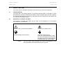
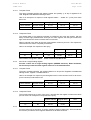
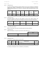
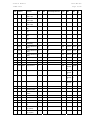
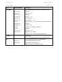
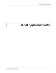
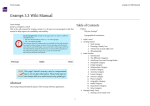
1
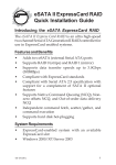
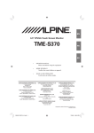
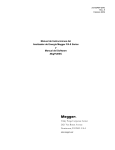
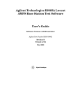
I400 (i4C, i4D, i4E, i4F, i4M, i4P, i4R, i4V, i4W) Manual iSTAT I400 Standard Transducer Publication Reference: I400/EN/M/F © 2013. ALSTOM, the ALSTOM logo and any alternative version thereof are trademarks and service marks of ALSTOM. The other names mentioned, registered or not, are the property of their respective companies. The technical and other data contained in this document is provided for information only. Neither ALSTOM, its officers or employees accept responsibility for, or should be taken as making any representation or warranty (whether express or implied), as to the accuracy or completeness of such data or the achievement of any projected performance criteria where these are indicated. ALSTOM reserves the right to revise or change this data at any time without further notice. I400/EN/M/F GRID Service Manual I400/EN M/F Page 1/46 iSTAT I400 HANDLING OF ELECTRONIC EQUIPMENT A person’s normal movements can easily generate electrostatic potentials of several thousand volts. Discharge of these voltages into semiconductor devices when handling circuits can cause serious damage, which often may not be immediately apparent but the reliability of the circuit will have been reduced. The electronic circuits of Alstom Grid products are immune to the relevant levels of electrostatic discharge when housed in their cases. Do not expose them to the risk of damage by withdrawing modules unnecessarily. Each module incorporates the highest practicable protection for its semiconductor devices. However, if it becomes necessary to withdraw a module, the following precautions should be taken to preserve the high reliability and long life for which the equipment has been designed and manufactured. 1. Before removing a module, ensure that you are a same electrostatic potential as the equipment by touching the case. 2. Handle the module by its front-plate, frame, or edges of the printed circuit board. Avoid touching the electronic components, printed circuit track or connectors. 3. Do not pass the module to any person without first ensuring that you are both at the same electrostatic potential. Shaking hands achieves equipotential. 4. Place the module on an anti-static surface, or on a conducting surface that is at the same potential as you. 5. Store or transport the module in a conductive bag. More information on safe working procedures for all electronic equipment can be found in BS5783 and IEC 60147-0F. If you are making measurements on the internal electronic circuitry of equipment in service, it is preferable that you are earthed to the case with a conductive wrist strap. Wrist straps should have a resistance to ground between 500k – 10M ohms. If a wrist strap is not available you should maintain regular contact with the case to prevent the build up of static. Instrumentation which may be used for making measurements should be earthed to the case whenever possible. Alstom Grid strongly recommends that detailed investigations on the electronic circuitry, or modification work, should be carried out in a Special Handling Area such as described in BS5783 or IEC 60147-0F. Service Manual I400/EN M/F Page 3/46 iSTAT I400 1. SAFETY SECTION This Safety Section should be read before commencing any work on the equipment. 1.1 Health and Safety The information in the Safety Section of the product documentation is intended to ensure that products are properly installed and handled in order to maintain them in a safe condition. It is assumed that everyone who will be associated with the equipment will be familiar with the contents of the Safety Section. 1.2 Explanation of symbols and labels The meaning of symbols and labels may be used on the equipment or in the product documentation, is given below. Caution: refer to product documentation Caution: risk of electric shock Protective/safety *earth terminal Functional *earth terminal Note: This symbol may also be used for a protective/safety earth terminal if that terminal is part of a terminal block or sub-assembly e.g. power supply. *NOTE: The term earth used throughout the product documentation is the direct equivalent of the North American term ground. Service Manual Page 4/46 iSTAT I400 2. I400/EN M/F INSTALLING, COMMISSIONING AND SERVICING Equipment connections Personnel undertaking installation, commissioning or servicing work on this equipment should be aware of the correct working procedures to ensure safety. The product documentation should be consulted before installing, commissioning or servicing the equipment. Terminals exposed during installation, commissioning and maintenance may present a hazardous voltage unless the equipment is electrically isolated. If there is unlocked access to the rear of the equipment, care should be taken by all personnel to avoid electrical shock or energy hazards. Voltage and current connections should be made using insulated crimp terminations to ensure that terminal block insulation requirements are maintained for safety. To ensure that wires are correctly terminated the correct crimp terminal and tool for the wire size should be used. Before energising the equipment it must be earthed using the protective earth terminal, or the appropriate termination of the supply plug in the case of plug connected equipment. Omitting or disconnecting the equipment earth may cause a safety hazard. The recommended minimum earth wire size is 2.5mm2, unless otherwise stated in the technical data section of the product documentation. Before energising the equipment, the following should be checked: Voltage rating, frequency and polarity VT ratio and phase sequence CT circuit rating and integrity of connections; Protective fuse rating; Integrity of earth connection (where applicable) Supply voltage Service Manual iSTAT I400 3. I400/EN M/F Page 5/46 EQUIPMENT OPERATING CONDITIONS The equipment should be operated within the specified electrical and environmental limits. 3.1 Current transformer circuits Do not open the secondary circuit of a live CT since the high level voltage produced may be lethal to personnel and could damage insulation. 3.2 External resistors Where external resistors are fitted to relays, these may present a risk of electric shock or burns, if touched. 3.3 Battery Replacement Where internal batteries are fitted they should be replaced with the recommended type and be installed with the correct polarity, to avoid possible damage to the equipment. 3.4 Insulation and dielectric strength testing Insulation testing may leave capacitors charged up to a hazardous voltage. At the end of each part of the test, the voltage should be gradually reduced to zero, to discharge capacitors, before the test leads are disconnected. 3.5 Insertion of modules and pcb cards These must not be inserted into or withdrawn from equipment whist it is energised since this may result in damage. 3.6 Fibre optic communication Where fibre optic communication devices are fitted, these should not be viewed directly. Optical power meters should be used to determine the operation or signal level of the device. Service Manual iSTAT I400 4. I400/EN M/F Page 6/46 OLDER PRODUCTS Electrical adjustments Equipment’s that require direct physical adjustments to their operating mechanism to change current or voltage settings should have the electrical power removed before making the change, to avoid any risk of electrical shock. Mechanical adjustments The electrical power to the relay contacts should be removed before checking any mechanical settings, to avoid any risk of electric shock. Draw out case relays Removal of the cover on equipment incorporating electromechanical operating elements, may expose hazardous live parts such as relay contacts. Insertion and withdrawal of extender cards When using an extender card, this should not be inserted or withdrawn from the equipment whilst it is energised. This is to avoid possible shock or damage hazards. Hazardous live voltages may be accessible on the extender card. Insertion and withdrawal of heavy current test plugs When using a heavy current test plug, CT shorting links must be in place before insertion or removal, to avoid potentially lethal voltages. Service Manual I400/EN M/F Page 7/46 iSTAT I400 5. DECOMMISSIONING AND DISPOSAL Decommissioning: The auxiliary supply circuit in the relay may include capacitors across the supply or to earth. To avoid electric shock or energy hazards, after completely isolating the supplies to the relay (both poles of any dc supply), the capacitors should be safely discharged via the external terminals prior to decommissioning. Disposal: It is recommended that incineration and disposal to water courses is avoided. The product should be disposed of in a safe manner. Any products containing batteries should have them removed before disposal, taking precautions to avoid short circuits. Particular regulations within the country of operation, may apply to the disposal of lithium batteries. Service Manual I400/EN M/F Page 8/46 iSTAT I400 6. TECHNICAL SPECIFICATIONS 6.1 Protective fuse rating The recommended maximum rating of the external protective fuse for this equipment is 16A, Red Spot type or equivalent, unless otherwise stated in the technical data section of the product documentation. Insulation class: IEC 61010-1 : 2002 Class II EN 61010-1 : 2002 Class II Insulation Category (Over voltage): IEC 61010-1 : 2002 Category II (600V), III (300V) EN 61010-1 : 2002 Category II (600V), III (300V) Environment: IEC 61010-1 : 2002 Pollution degree 2 (600V), 3 (300V) Compliance is demonstrated by reference to generic safety standards. EN 61010-1 : 2002 Pollution degree 2 (600V), 3 (300V) Product Safety: 2006/95/EC EN 61010-1 : 2002 Compliance with the European Commission Low Voltage Directive. Compliance is demonstrated by reference to generic safety standards. Service Manual iSTAT I400 I400/EN M/F Page 9/46 CONTENT 1. SAFETY SECTION 3 1.1 Health and Safety 3 1.2 Explanation of symbols and labels 3 2. INSTALLING, COMMISSIONING AND SERVICING 4 3. EQUIPMENT OPERATING CONDITIONS 5 3.1 Current transformer circuits 5 3.2 External resistors 5 3.3 Battery Replacement 5 3.4 Insulation and dielectric strength testing 5 3.5 Insertion of modules and pcb cards 5 3.6 Fibre optic communication 5 4. OLDER PRODUCTS 6 5. DECOMMISSIONING AND DISPOSAL 7 6. TECHNICAL SPECIFICATIONS 8 6.1 Protective fuse rating 8 7. INTRODUCTION 13 8. TECHNICAL DATA 14 8.1 Input Ratings – A.C. transducers 14 8.1.1 Voltage transducers 14 8.1.2 Current transducers 14 8.1.3 Frequency transducers 14 8.1.4 Watts, VArs, Phase Angle 15 8.1.5 Multi-function transducers 15 8.2 Input Ratings – D.C. transducers (i4D) 15 8.2.1 General 15 8.2.2 Tap Position Indicator 15 8.2.3 D.C. Voltage 15 8.2.4 D.C. Current 16 8.2.5 Resistance 16 8.2.6 Temperature (RTD) 16 8.3 Auxiliary Supply Input 17 8.3.1 Universal AC/DC auxiliary supply 17 8.3.2 AC auxiliary supply 17 8.4 Analogue Output Ratings – A.C. transducers 17 I400/EN M/F Page 10/46 Service Manual iSTAT I400 8.4.1 Output Ranges 17 8.4.2 Accuracy 17 8.5 Analogue Output Ratings – D.C. transducers 18 8.5.1 Output Ranges 18 8.5.2 Accuracy 18 8.6 Pulsed energy switches (I4E) 18 8.6.1 Output range 18 8.6.2 Accuracy 18 8.7 Communication ports 18 8.7.1 EIA232 Port 18 8.7.2 EIA485 Port 19 8.8 Electrical Environment 19 8.9 Environmental Conditions 19 8.9.1 Atmospheric environment 19 8.9.2 Construction 20 9. INSTALLATION 21 9.1 Dimensions 21 9.2 Mounting 21 9.3 Internal Jumpers 22 10. CONNECTIONS 23 10.1 Auxiliary Supply Connection 23 10.1.1 A.C. auxiliary supply 23 10.1.2 Universal auxiliary supply 23 10.2 Communications Connections 23 10.2.1 EIA232 port 23 10.2.2 EIA485 port 24 10.3 Input Connections 24 10.3.1 A.C. input transducers 24 10.3.2 D.C. input transducers 25 10.4 Output Connections 26 11. RELATED DOCUMENTS 27 12. MODBUS IMPLEMENTATION 28 12.1 TRANSACTIONS 28 12.1.1 Request 28 12.1.2 Response 28 12.1.3 Example of Request - Response cycle 28 12.2 FRAMING 29 12.2.1 RTU framing 29 12.3 SUPPORTED FUNCTIONS AND USAGE 29 Service Manual iSTAT I400 I400/EN M/F Page 11/46 12.3.1 03 read from holding registers 30 12.3.2 04 read from input registers 30 12.3.3 06 write to a single holding register 31 12.3.4 16 (10 HEX) write to one or more registers 31 12.3.5 17 (11HEX) report slave id 32 12.3.6 77 (4D HEX) read measurement string 33 12.3.7 82 (52 HEX) re-read output buffer 35 12.4 ERROR RESPONSES 35 12.4.1 Exception codes 36 13. MODBUS ADDRESS MAP FOR AC MEASUREMENT TRANSDUCERS 37 14. MODBUS ADDRESS MAP FOR DC MEASUREMENT TRANSDUCERS 43 15. MODBUS DATA TYPES 44 Service Manual I400/EN M/F Page 12/46 iSTAT I400 BLANK PAGE Service Manual I400/EN M/F Page 13/46 iSTAT I400 7. INTRODUCTION iSTAT I400 digital transducers provide local and remote indication for precision electrical measurement and control when used with instruments, recorders, data loggers and SCADA (Supervisory Control and Data Acquisition) systems. The I400 range contains the following type of devices: (1) A.C. input transducers I4CA Mean-Sensing Current (single phase) I4VA Mean-Sensing Voltage (single phase) I4CD, I4CF RMS Current (single-, three-phase) I4VD, I4VF RMS Voltage (single-, three-phase) I4F Frequency I4P Phase Angle I4W Watts I4R VArs I4M Multi-function (does not include i4MT, i4MC or i4MV) I4E Multi-function Energy (2) D.C. input transducers I4DA Tap Position Indicator (T.P.I.) I4DB D.C. Voltage I4DC D.C. Current I4DF Resistance I4DG Temperature (RTD input) (3) Ancillary Equipment I4X Communications Interfaces (separate manual) Provision of both analogue outputs, pulsed electronic switches (I4E only) and MODBUS communication allows integration within existing sites and also in new facilities, where digital communications can be used. The software package QDSP is used to program the I400 transducers. The ease of programmability of digital transducers is an important feature in the provision of cost effective system control. Systems can be easily changed or expanded as required. Scaling may be programmed on site, thereby avoiding costly project delays. NOTE: When programming a transducer using the QDSP, it may additionally be necessary to physically change jumper positions within the transducer case. Refer to section 9.3 for further details. Applications are found in electrical utilities, energy management systems, SCADA, building management and control systems, and process control environments. Service Manual I400/EN M/F Page 14/46 8. TECHNICAL DATA 8.1 Input Ratings – A.C. transducers 8.1.1 Voltage transducers iSTAT I400 Mean-sensing: Nominal voltage (U n ) 57.7V, 63.5V, 69.3V, 100V, 110V, 120V, 127V, 220V, 240V, 380V, 400V, 415V, 440V Measuring range 10 to 120% Un Burden 2 VA Overload 1.2 x Un continuously 2 x Un for 1s RMS: 8.1.2 Nominal voltage (U n ) 50 – 500 V Measuring range 0 to 120% Un Burden 1mA x Un Overload 1.5 x Un continuously 2 x Un for 1s Current transducers Mean-sensing: Nominal current (I n ) 1A, 1.2A, 5A, 6A Measuring range 0 to 120% In Burden 2 VA Overload 2 x In continuously 20 x In for 1s RMS: 8.1.3 Nominal current (I n ) 0.5A - 5A Measuring range 0 to 120% In Burden 0.5 VA Overload 2 x In continuously 20 x In for 1s Frequency transducers Nominal frequency (f n ) 50Hz or 60Hz Measuring range 45Hz to 65Hz Burden (voltage circuit) 1mA x Un Overload (voltage circuit) 1.2 x Un continuously 2 x Un for 1s Service Manual I400/EN M/F Page 15/46 iSTAT I400 8.1.4 8.1.5 Watts, VArs, Phase Angle Nominal voltage (U n ) 50 – 500V Nominal current (I n ) 0.5A - 5A Measuring range 0 to 120% In, 0 to 120% Un Burden (voltage circuit) 1mA x Un Overload (voltage circuit) 1.2 x Un continuously 2 x Un for 1s Burden (current circuit) 0.5 VA Overload (current circuit) 2 x In continuously 20 x In for 1s Multi-function transducers Nominal voltage (U n ) 50 – 500V Nominal current (I n ) 0.5A - 5A Measuring range 0 to 120% In, 0 to 120% Un Burden (voltage circuit) 0.2mA x Un Overload (voltage circuit) 1.5 x Un continuously 2 x Un for 1s Burden (current circuit) 0.01 x In 2 Overload (current circuit) 2 x In continuously 20 x In for 1s 8.2 Input Ratings – D.C. transducers (i4D) 8.2.1 General Some of the DC Transducers are defined with different measurement ranges available. It is important that the correct range is selected when ordering as the top of the required measurement range cannot be set below the bottom of the unit’s range, i.e. if DC Voltage 1V to 50V unit is purchased the top of the configured range can not be set below 1V. 8.2.2 8.2.3 Tap Position Indicator Nominal resistance (R n ) 100 to 500k Number of steps 1 to 100 Minimum step value 30 Measuring voltage <2.2V Lead resistance <50 per lead Burden <0.5 VA D.C. Voltage Nominal voltage (U n ) ±50mV to ±300V programmable Measuring ranges 50mV to 1V 1V to 50 V 50V to 300V Burden <0.5 VA Overload 1.2 x Un permanently 2 x Un for 1s Input impedance >2.5M Input impedance 250k Input impedance 2.5M Service Manual I400/EN M/F Page 16/46 8.2.4 8.2.5 8.2.6 iSTAT I400 D.C. Current Nominal current (I n ) 0 – ±100mA (programmable) Measuring ranges 1mA to 10mA 10mA to 100mA Burden <0.5 VA Overload 2 x In continuously 20 x In for 1s Input impedance 100 Input impedance 10 Resistance Nominal resistance (R n ) 10 to 50k (programmable) 100 to 500k (programmable) Measuring voltage <2.2V Lead resistance <10 per lead Burden <0.5 VA Temperature (RTD) RTD sensor type Pt100, Pt1000, Ni100 Measuring method 2-wire, 3-wire or 4-wire Measuring ranges -200°C to 850°C (Pt), -60°C to 250°C (Ni) (programmable) RTD sensor limit values 20 to 10k Measuring voltage <2.2V Lead resistance <10 per lead Burden <0.5 VA Service Manual I400/EN M/F Page 17/46 iSTAT I400 8.3 Auxiliary Supply Input 8.3.1 Universal AC/DC auxiliary supply 8.3.2 Nominal voltage Operative range DC 24 V to 220 V 19 V to 300 V AC 50 V to 230 V (40…70 Hz) 40 V to 276 V (40…70 Hz) Burden <3VA AC auxiliary supply AC Nominal voltage (Ur) Operative range 57.7 V 63.5 V 69.3 V 100 V 110 V 115 V 120 V 208 V 230 V 80…120 % Ur Frequency Range 45…65 Hz Burden <3VA 8.4 Analogue Output Ratings – A.C. transducers 8.4.1 Output Ranges DC Current output Nominal values 0..1mA, -1..0..1mA, 0..5mA, -5..0..5mA, 0..10mA, 10..0..10mA, 0..20mA, 4..20mA, -20..0..20mA Compliance voltage 15V (10V for i4CA, i4VA) Response time (0…99.5%) <300 ms DC Voltage output 8.4.2 Nominal values 0..1V, -1..0..1V, 0..10V, -10..0..10V Maximum current 20mA Response time (0…99.5%) <300 ms Accuracy EN 60688 (analogue outputs) and via communications. % of full scale unless otherwise stated. Voltage (Mean Sensing/RMS) ±0.5% Voltage (Suppressed Zero RMS) ±0.5% Un Phase current ±0.5% Neutral current ±1% Power ±0.5% Phase angle ±0.2° Demand values ±1% Frequency ±0.1% (0.01% via communications) * THD ±1% * Accuracy of frequency is % of centre scale frequency Service Manual I400/EN M/F Page 18/46 iSTAT I400 8.5 Analogue Output Ratings – D.C. transducers 8.5.1 Output Ranges DC Current output Nominal values 0..1mA, -1..0..1mA, 0..5mA, -5..0..5mA, 0..10mA, 10..0..10mA, 0..20mA, 4..20mA, -20..0..20mA Compliance voltage 15V Response time (0…99.5%) 500 ms DC Voltage output 8.5.2 Nominal values 0..1V, -1..0..1V, 0..10V, -10..0..10V Maximum current 20mA Response time (0…99.5%) 500 ms Accuracy Analogue outputs and via communications. % of full scale. T.P.I. ±0.5% DC Voltage ±0.5% DC Current ±0.5% Resistance ±0.5% Temperature (RTD) ±0.5% 8.6 Pulsed energy switches (I4E) 8.6.1 Output range 8.6.2 Type Pulsed electronic switch Pulse width 2 to 510 ms Signal level 40V ac or dc maximum, 27mA maximum resistive load Accuracy Energy 8.7 Communication ports 8.7.1 EIA232 Port Active energy Class 1, Reactive energy Class 2 (EN61036 and EN61268) Connection type Point to point Signal levels EIA232 Cable type Screened multi-core Maximum cable length 15m Connector Screw terminals Isolation 3.7kV rms for 1 minute between all terminals and all other circuits Transmission mode Asynchronous Protocol MODBUS RTU Data rate 1200 to 115200 bits/s Service Manual I400/EN M/F Page 19/46 iSTAT I400 8.7.2 8.8 EIA485 Port Connection type Multi-drop (32 connections per link) Signal levels EIA485 Cable type Screened twisted pair Maximum cable length 1000m Connector Screw terminals Isolation 3.7kV rms for 1 minute between all terminals and other circuits Transmission mode Asynchronous Protocol MODBUS RTU Data rate 1200 to 115200 bits/s Electrical Environment Insulation EN 61010-1: 1990 Insulation Class II (500V RMS) Tested at 3.7kV peak EMC compliance 2004/108/EC The following generic standards were used to establish conformity. EN 61326-1: 1997 Electrical equipment for measurement, control, and laboratory use. EMC Requirements Low Voltage Directive 2006/95/EC The following generic standards were used to establish conformity. EN 61010-1: 2002 8.9 Environmental Conditions 8.9.1 Atmospheric environment Electrical equipment for measurement, control, and laboratory use. Temperature and humidity EN 60688: 1992 Class 2 JVF (DIN 40 040) Nominal range of operation -10°C to 55°C Storage and transit -40°C to 70°C Temperature coefficient (A.C. transducers) 0.02% / °C Temperature coefficient (D.C. transducers) 0.05% / °C Annual mean relative humidity 75% Service Manual I400/EN M/F Page 20/46 8.9.2 iSTAT I400 Construction Material Flammability protection UL 94 V-0 Enclosure protection IEC 60529: 1989 IP 50 (IP 20 for connection terminals) Mounting EN 50022: 1978 DIN rail 35x15 mm Dimensions 100mm Case 100x75x104.5 mm 45mm Case 45x75x104.5 mm AC auxiliary supply units <0.6kg Weight Universal aux. supply units <0.5kg Service Manual I400/EN M/F Page 21/46 iSTAT I400 9. INSTALLATION 9.1 Dimensions 75 104.5 44.8 All dimensions in mm Maximum section of connection wires < = 4.0mm² for one wire < = 1.5mm² for two wires 75 100 104.5 FIGURE 1 : I400 DIMENSIONS 9.2 Models with case width 44.8mm I4CA, I4VA, I4CD, I4VD, I4F and I4D Models with case width 100mm I4P, I4W, I4R, I4M and I4E Mounting Mounting is at the rear of the unit, for 35x15 mm DIN rail according to EN 50022: 1978 . Service Manual I400/EN M/F Page 22/46 9.3 iSTAT I400 Internal Jumpers On programmable models of transducers, the analogue output values can be programmed using the QDSP software via the EIA232 or EIA485 communication port. However, before this is done, the hardware output range of each analogue output must be selected, on some versions (i4C, i4V, i4F, i4Dx) and on early models of other variants a physical jumper position on the output module within the transducer case needs to be changed. On later models (except i4C, i4V, i4F, i4Dx) the configuration is done completely using the configuration software and no physical changes will be required. It is possible to choose between three hardware output ranges: 0…±5 mA 0…±20 mA 0…±10 V By selecting one of these three hardware output ranges, it is possible to program any linear or multiple-slope (with maximum 5 break points) output characteristic using the QDSP setting software. Caution: Electrical adjustments Equipment that requires direct physical adjustments to their operating mechanism to change current or voltage settings, should have the electrical power removed before making the change, to avoid any risk of electrical shock. Where the internal jumper needs to be set, the location of the jumpers is as shown in the diagram below. Single output transducers will have only Jumper 1 fitted. FIGURE 2 : I400 JUMPER POSITIONS For information, the QDSP setting software displays for each analogue output, on the Output graphical display in the Device Settings window, the positions to which the jumpers must be set to match the currently-selected output type. If it is attempted in QDSP to select an output range which is not in the currently-selected hardware range, QDSP will display an error message, to indicate that the jumper positions must be physically changed. Service Manual I400/EN M/F Page 23/46 iSTAT I400 10. CONNECTIONS 10.1 Auxiliary Supply Connection An auxiliary power supply is necessary for all I400 transducers, except for the self-powered mean sensing current and voltage transducers (I4CA and I4VA). 10.1.1 A.C. auxiliary supply If the I400 transducer is fitted with an A.C. auxiliary supply, the terminal allocations are as follows: 10.1.2 Terminal Number Terminal Marking Description 13 ~ Live 14 ~ Neutral Universal auxiliary supply If the I400 transducer is fitted with a universal AC/DC auxiliary supply, the terminal allocations are as follows: 10.2 Terminal Number Terminal Marking Description 13 +/~ + / Live 14 – /~ Common / Neutral Communications Connections To be able to establish communication with an I400 unit, it has to be physically connected to the serial port of the computer or Remote Terminal Unit, etc. I400 transducer connections are identified on the transducer label beside the screw terminals. In order to communicate with the device, auxiliary power must be applied to the device, and the communications connection must be correctly wired. 10.2.1 EIA232 port If the I400 transducer is fitted with an EIA232 communications port, the terminal allocations are as follows: Description I400 Terminal number Receive 21 (23 I4M4 only) Signal Ground 22 (24 I4M4 only) Transmit 23 (25 I4M4 only) Terminal RS232 9 pin connection marking PC Terminal Rx 3 5 Tx 2 The EIA232 communications port is configured as a DTE (Data Terminal Equipment) device, which means that a crossover cable will be required to connect to a standard EIA232 serial port on a PC (also a DTE). The maximum connection length is 15 metres. Service Manual I400/EN M/F Page 24/46 10.2.2 iSTAT I400 EIA485 port If the I400 transducer is fitted with an EIA485 communications port, the terminal allocations are as follows: Terminal Number Terminal Marking Description 21 (23 I4M4 only) A TxRxA (DATA+) 22 (24 I4M4 only) C No connection 23 (25 I4M4 only) TxRxB (DATA-) B Two-wire EIA485 only is used. An EIA485 port will be required on the Master system and on any PC being used with QDSP an external EIA485 (2-wire) interface is required connected to the PC’s USB (or EIA232) port. The maximum connection length is 1000 metres. Conductors A and B should be terminated with a 120 terminating resistor. 10.3 Input Connections 10.3.1 A.C. input transducers 2 11 1 u v U V 3 k L L N N l L K Volts, frequency 1 2 Current 11 3 1 u v U k U L1 v U V L1 l k 3 L L K Power - 3 wire balanced 1 2 1 2 3 5 7 8 L2 L3 k V v k l U K L k K 3 11 9 u U 8 L3 Power - single phase L1 5 l K L2 V N V u 2 L1 l L l V K L L3 N Power - 3 wire unbalanced Power - 4 wire balanced Service Manual I400/EN M/F Page 25/46 iSTAT I400 1 2 3 4 5 6 7 u u 9 11 1 3 4 6 7 9 u k k l k L1 l k K L3 l K N K L2 L3 L L x x 8 k l L K N 5 l L K L Triple current Power - 4 wire unbalanced 2 l k L1 11 x L1 L2 L3 N Triple voltage NOTE: 10.3.2 The diagrams referred to as ‘Power’ are applicable to Watt, VAr, Phase Angle and Multifunction transducers. D.C. input transducers 1 2 3 4 1 Ri Ru Ru Ri 3 3 -U +U 2 -I +I Rx 100% 0% Tap Position Indicator 1 4 Ri Ri Rx Resistance, Temperature (RTD) - 2-wire DCVoltage 1 3 Ri 4 Ru Ri Rx Resistance, Temperature (RTD) - 3-wire DCCurrent 1 3 2 4 Ri RuRu Ri Rx Resistance, Temperature (RTD) - 4-wire Service Manual I400/EN M/F Page 26/46 10.4 iSTAT I400 Output Connections The I400 transducer output terminal allocations are as follows, where fitted: Terminal Number Terminal Marking Description 15 + Output 1 + 16 – Output 1 – 17 + Output 2 + 18 – Output 2 – 19 + Output 3 + 20 – Output 3 – 21 (I4M4 only) – Output: 4+ 22 (I4M4 only) – Output: 4 – By default single output transducers always use Output 1 terminals (15 and 16). I4M Multifunction transducers may be fitted with none, one, two, three or four outputs depending on order option. I4E Multifunction energy transducers are always fitted with a pulse electronic switch on Output 1 terminals (15 and 16). If fitted, the other two outputs can be ordered as either additional electronic switches or analogue outputs. All D.C. input transducers are single output transducers. Service Manual I400/EN M/F Page 27/46 iSTAT I400 11. RELATED DOCUMENTS Ref Title 1 QDSP Technical Manual 2 Application Guide for Electrical Measuring Transducers Service Manual I400/EN M/F Page 28/46 iSTAT I400 12. MODBUS IMPLEMENTATION 12.1 TRANSACTIONS Communication operates on a master-slave basis where only one device (the master) can initiate transactions called 'Requests'. The other devices (slaves) respond by supplying the requested data to the master. This is called the 'Request - Response Cycle'. Master to slave request: Device address Function Code nx8 bit data bytes Error check nx8 bit data bytes Error check Slave to master response: Device address 12.1.1 Function Code Request This Master to Slave transaction takes the form: Device address: Master addressing a slave (Address 0 is used for the broadcast address, which all slave devices recognise.) Function code: E.g. 03 asks the slave to read its Holding registers and respond with their contents. Data bytes: Tells the slave which register to start at and how many registers to read. 12.1.2 Response This Slave to Master transaction takes the form: Device address: To let the master know which slave is responding. Function code: This is an echo of the request function code. Data bytes: Contains the data collected from the slave. 12.1.3 12.1.3.1 Example of Request - Response cycle Input to I400 transducer: Van = 57.4 V 50Hz Data held in Input Registers: 30057(10) & 30058(10) Starting register 30057(10) - 30000(10) offset = 57(10) = 00 39(16) Request Frame Starting Register Register Count CRC LO HI Slave Address Function code HI LO HI LO 21 04 00 39 00 02 Service Manual I400/EN M/F Page 29/46 iSTAT I400 12.1.3.2 Response Frame Register Data CRC LO HI Slave Address Function code Byte count HI LO HI LO 21 04 04 FD 00 E0 1F Response register data, FD 00 E0 1F, is decoded as: Exponent (8 m.s.b., signed) = FD (16) = -3 (10) Value (24 l.s.b., unsigned) = 00 E0 1F (16) = 57375 (10) Complete number (decimal) = 57375 x 10-3 = 57.375 V 12.2 FRAMING There are two types of message framing for Modbus serial communications, ASCII or RTU. The I400 family of transducers supports RTU framing only. 12.2.1 RTU framing In RTU mode, messages start and end with a silent interval of at least 3.5 character times (t1-t2-t3-t4 as shown below). The advantage of this mode of framing is that it enables a greater character density and a better data throughput. However, each message must be transmitted in a continuous stream. If a silent interval of more than 1.5 character times occurs before completion of the frame, the device flushes the incomplete message and assumes that the next byte will be the address field of a new message. Start Address Function Data CRC Check End t1-t2-t3-t4 8 bits 8 bits n x 8 bits 16 bits t1-t2-t3-t4 The Cyclic Redundancy Check (CRC) field is two bytes, containing a 16 bit binary value. The CRC value is calculated by the transmitting device, which appends the CRC to the message. The receiving device recalculates a CRC during receipt of the message, and compares the calculated value to the actual value it received in the CRC field. If the two values are not equal an error results. The CRC-16 calculation is an industry standard method used for error detection. One frame is transmitted as 1 start bit, 8 data bits and 2 stop bit. If parity is selected then the frame is transmitted as 1 start bit, 8 data bits, and 1 stop bit. Where n > 1 data is transmitted most significant byte first. The CRC check is transmitted least significant byte first. 12.3 SUPPORTED FUNCTIONS AND USAGE Code Code Function References DEC HEX 3 03 to read from holding registers (4XXXX memory references) 4 04 to read from input registers (3XXXX memory references) 6 06 to write to a single holding register (4XXXX memory references) 16 10 to write to one or more holding registers (4XXXX memory references) 17 11 report slave ID 6 characters 77 4D read measurement string 1 byte value code (request) 82 52 re-read output buffer Use after broadcast request Service Manual I400/EN M/F Page 30/46 12.3.1 iSTAT I400 03 read from holding registers Reads the content of Holding Registers (4XXXX references) in the slave. Broadcast is also supported. 12.3.1.1 Request Frame The query message specifies the starting register and quantity of registers (1 to 28) to be read. Registers are addressed starting at zero. Here is an example of a request to read register 40043 “Connection Mode” from slave device 33 (=21(16) ) 12.3.1.2 Starting Register Register Count CRC LO HI Slave Address Function Code HI LO HI LO 21 03 00 2B 00 01 Response Frame The register data in the response message is packed as two bytes per register, with the binary contents right justified within each byte. For each register, the first byte contains the high order bits and the second contains the low order bits. Data is scanned in the slave at the rate of 28 registers maximum per scan. The response is returned when the data is completely assembled. Here is an example of a response to the query: Register Data CRC LO HI Slave Address Function Code Byte Count HI LO 21 03 02 00 05 The contents of register 40043 is 00 05 (=’4u – 3 phase 4 wire unbalanced’). 12.3.2 04 read from input registers Reads the content of Input Registers (3XXXX references) in the slave. Broadcast is also supported Service Manual I400/EN M/F Page 31/46 iSTAT I400 12.3.2.1 Request Frame The query message specifies the starting register and quantity (1 to 28) of registers to be read. Registers are addressed starting at zero. Here is an example of a request to read registers 30057 ... 30058 “U1” (=Van) from slave device 33: 12.3.2.2 Starting Register Register Count CRC LO HI Slave Address Function Code HI LO HI LO 21 04 00 39 00 02 Response Frame The register data in the response message is packed as two bytes per register, with the binary contents right justified within each byte. For each register, the first byte contains the high order bits and the second contains the low order bits. Data is scanned in the slave at the rate of 28 registers maximum per scan. The response is returned when the data is completely assembled. Here is an example of a response to the query: Register Data Register Data Slave Address Function Code Byte Count HI LO HI LO 21 04 04 FD 00 E0 1F CRC LO HI The contents of registers 30036 ... 30037 are FD 00 and E0 1F hex. 12.3.3 06 write to a single holding register Pre-sets a value into a single holding register (4XXXXX reference). When broadcast, the function pre-sets the same register reference in all attached slaves. 12.3.3.1 Request Frame The query message specifies the register reference to be pre-set. Registers are addressed starting at zero; register 1 is addressed as 0. Here is an example of a request to pre-set register 40010 “Active Access Level” to 00 02 hex (Level 2 access) in slave device 33: 12.3.3.2 Register Address Register Data CRC LO HI Slave Address Function Code HI LO HI LO 21 06 00 0A 00 02 Response Frame The normal response is an echo of the query, returned after the register contents have been pre-set. Here is an example of a response to the query: 12.3.4 Register Address Register Data CRC LO HI Slave Address Function Code HI LO HI LO 21 06 00 0A 00 02 16 (10 HEX) write to one or more registers Pre-sets values into a sequence of holding registers (4XXXX references). When broadcast, the function pre-sets the same register references in all attached slaves. Service Manual I400/EN M/F Page 32/46 12.3.4.1 iSTAT I400 Request Frame The query message specifies the register references to be pre-set. Registers are addressed starting at zero; register 1 is addressed as 0. Here is an example of a request to pre-set two registers starting at 40008 to 41 41 and 41 41 hex (Enter Level 2 Password AAAA), in slave device 33: 12.3.4.2 Starting Register Byte Register Address Count Count Data Code HI LO HI LO 10 00 08 00 02 Slave Function Address 21 CRC HI LO HI LO 04 LO HI 41 41 41 41 Response Frame The normal response returns the slave address, function code, starting address, and quantity of registers pre-set. Here is an example of a response to the query shown above. 12.3.5 Slave Function Starting Address Register Count CRC Address Code HI LO HI LO LO HI 21 10 00 08 00 02 17 (11HEX) report slave id Returns a description of the type of controller present at the slave address. 12.3.5.1 Request Frame Here is an example of a request to report the ID of slave device 33: CRC 12.3.5.2 Slave Address Function Code 21 11 LO HI Response Frame The format of a normal response is shown below: Slave Function Address Code 21 11 Byte Register Data Count HI LO HI LO ….. 10 49 34 4D 20 20 20 54 72 61 6E 73 64 75 63 65 72 The string in the response is "I4M Transducer" (16 characters). CRC LO HI Service Manual I400/EN M/F Page 33/46 iSTAT I400 12.3.6 77 (4D HEX) read measurement string Reads the measurement value as an ASCII string. Broadcast is also supported. The value codes are listed in the following table: Value Value Byte Example Code DEC Code HEX Measurement Value Count String Data 1 01 Frequency 7 "50.004 " 2 02 Frequency 1 7 "50.004 " 3 03 Frequency 2 7 "50.004 " 4 04 Frequency 3 7 "50.004 " 5 05 U1 7 "48.043k" 6 06 U2 7 "48.115k" 7 07 U3 7 "48.183k" 8 08 Uavg (phase to neutral) 7 "48.113k" 9 09 j12 (angle between U1 and U2) 7 "+000.00" 10 0A j23 (angle between U2 and U3) 7 "+000.02" 11 0B j31 (angle between U3 and U1) 7 "-000.02" 12 0C U12 6 "00.07k" 13 0D U23 6 "00.07k" 14 0E U31 6 "00.14k" 15 0F Uavg (phase to phase) 6 "00.09k" 16 10 I1 7 "079.94 " 17 11 I2 7 "080.58 " 18 12 I3 7 "080.40 " 19 13 IN 6 "240.9 " 21 15 Iavg 7 "080.31 " 22 16 Total I 7 "240.91 " 23 17 Active Power Total (Pt) 8 "+8147.3k" 24 18 Active Power Phase L1 (P1) 8 "+2697.6k" 25 19 Active Power Phase L2 (P2) 8 "+2724.2k" 26 1A Active Power Phase L3 (P3) 8 "+2725.1k" 27 1B Reactive Power Total (Qt) 12 "8225.8kvar L" 28 1C Reactive Power Phase L1 (Q1) 12 "2727.3kvar L" 29 1D Reactive Power Phase L2 (Q2) 12 "2750.8kvar L" 30 1E Reactive Power Phase L3 (Q3) 12 "2747.3kvar L" 31 1F Apparent Power Total (St) 7 "11.578M" 32 20 Apparent Power Phase L1 (S1) 7 "3836.0k" 33 21 Apparent Power Phase L2 (S2) 7 "3871.4k" 34 22 Apparent Power Phase L3 (S3) 7 "3869.6k" 35 23 Power Factor Total (PFt) 8 "+0.704 L" 36 24 Power Factor Phase 1 (PF1) 8 "+0.703 L" 37 25 Power Factor Phase 2 (PF2) 8 "+0.704 L" 38 26 Power Factor Phase 3 (PF3) 8 "+0.704 L" Service Manual I400/EN M/F Page 34/46 Value Value Code DEC Code HEX 39 27 40 28 41 iSTAT I400 Byte Example Measurement Value Count String Data Power Angle Total (atan2(Pt,Qt)) 7 "+045.27" (angle between U1 and I1) 7 "+041.46" 29 2 (angle between U2 and I2) 7 "+041.05" 42 2A 3 (angle between U3 and I3) 7 "+041.24" 43 2B Internal Temperature 7 "+036.84" 44 2C U1 THD% 6 "002.81" 45 2D U2 THD% 6 "002.70" 46 2E U3 THD% 6 "002.70" 47 2F U12 THD% 6 "000.55" 48 30 U23 THD% 6 "000.55" 49 31 U31 THD% 6 "000.55" 50 32 I1 THD% 6 "034.91" 51 33 I2 THD% 6 "036.34" 52 34 I3 THD% 6 "035.65" DYNAMIC DEMAND VALUES 53 35 I1 10 "I1=79.70 A" 54 36 I2 10 "I2=80.07 A" 55 37 I3 10 "I3=79.91 A" 56 38 Apparent Power Total (St) 11 "St=11.53MVA" 57 39 Active Power Total (Pt) - (positive) 11 "Pt=+8.051MW" 58 3A Active Power Total (Pt) - (negative) 11 "Pt=-0.000MW" 59 3B Reactive Power Total (Qt) - L 14 "Qt=8.253Mvar L" 60 3C Reactive Power Total (Qt) - C 14 "Qt=0.000Mvar C" MAX DEMAND SINCE LAST RESET 61 3D I1 10 "I1=082.6 A" 62 3E I2 10 "I2=082.6 A" 63 3F I3 10 "I3=082.3 A" 64 40 Apparent Power Total (St) 11 "St=12.02MVA" 65 41 Active Power Total (Pt) - (positive) 11 "Pt=+08.29MW" 66 42 Active Power Total (Pt) - (negative) 11 "Pt=-00.00MW" 67 43 Reactive Power Total (Qt) - L 14 "Qt=08.71Mvar L" 68 44 Reactive Power Total (Qt) - C 14 "Qt=00.00Mvar C" Service Manual I400/EN M/F Page 35/46 iSTAT I400 12.3.6.1 Request Frame The query message specifies the value code of the measurement to be read. Here is an example of the query to read U1 (Van), value code 05, from slave device 33: 12.3.6.2 Slave Function Address Code 21 4D CRC Value Code LO HI 05 Response Frame The ASCII string in the response message is packed as data bytes. The quantity of data bytes depends on the value code. Here is an example of a response to the query: Slave Function Byte String Data CRC Address Code Count 1. 2. 3. 4. 5. 6. 7. LO HI 21 4D 07 34 38 2E 30 34 33 6B This reply is the ASCII string “48.043k”. 12.3.7 82 (52 HEX) re-read output buffer This function should be used after the broadcast request. The addressed slave transmits the response frame of the previous request. 12.3.7.1 Request Frame Here is an example of a request to re-read the output buffer of slave device 33: CRC 12.3.7.2 Slave Address Function Code 21 52 LO HI Response Frame The response to the query depends on the previous function code. 12.4 ERROR RESPONSES When a slave detects an error other than a CRC error, a response will be sent to the master. The most significant bit of the function code byte will be set to 1 (i.e. the function code sent from the slave will be equal to the function code sent from the master plus 128). The following byte will be an exception code indicating the type of error that occurred. The slave will ignore transmissions received from the master with CRC errors. An example of an illegal request and the corresponding exception response is shown below. The request in this example is to read registers 0201H to 0209H. If these addresses are not supported in the slave then the following occurs: Request Message Starting Register Register Count Address Function Code HI LO HI LO CRC 01 01 02 01 00 08 6D B4 Service Manual I400/EN M/F Page 36/46 iSTAT I400 Exception Response Message 12.4.1 Address Function Code Exception Code CRC 01 81 02 C1 91 Exception codes Code Name Meaning 01 ILLEGAL FUNCTION The function code transmitted is not one of the functions supported by the slave. 02 ILLEGAL DATA ADDRESSES The data address received in the request is not an allowable value for the slave. Write to password protected registers. 03 ILLEGAL DATA VALUE The value referenced in the data field transmitted by the master is not within range for the selected data address. The register count is greater than 28 (functions 03 and 04). 06 SLAVE DEVICE BUSY The slave is engaged in processing a long duration program command. The master should re-transmit the message later when the slave is free. Service Manual I400/EN M/F Page 37/46 iSTAT I400 MODBUS ADDRESS MAP FOR AC MEASUREMENT TRANSDUCERS Code Address Contents Data Ind Values/Dependencies Type Example: I4M3 Data Min 30000 memory reference SYSTEM DATA 04 30001 30008 Model Number T_Str16 04 30009 30012 Serial Number T_Str8 Data 04 30013 Software Reference T1 Data 04 30014 Modbus Max. Register T1 Read at Once Use 28 if (reg.30013) > 103 Data 04 30015 30018 Configuration Time Stamp T_Time Data 04 30019 30022 Calibration Time Stamp T_Time Data 04 30023 30024 Reserved Locations 04 30025 Hardware – I/O 4 T1 3 Jumperless Analogue Output 04 30026 Hardware - I/O 1 T1 0 No I/O 1 Unipolar Analogue Output 2 Bipolar Analogue Output 3 Jumperless Analogue Output 4 Pulse Output 5 Tariff Input Data 04 30027 Hardware - I/O 2 T1 see Hardware - I/O 1 Data 04 30028 Hardware - I/O 3 T1 see Hardware - I/O 1 Data 04 30029 Hardware T1 Communication Type 0 No Communication Data 1 RS 232 2 RS 485 Bit-0 External Auxiliary Supply Bit-1 N - Neutral Bit-2 Phase Voltage L1 Bit-3 Phase Voltage L2 Bit-4 Phase Voltage L3 Bit-5 Phase Current L1 Bit-6 Phase Current L2 Bit-7 Phase Current L3 04 30030 Hardware Configuration T1 Data 04 30037 Energy Counter 1 Exponent T2 Data 04 30038 Energy Counter 2 Exponent T2 Data 105 Max Step 13. Service Manual I400/EN M/F Page 38/46 Code Address Contents Data Ind Values/Dependencies Type 04 30039 Energy Counter 3 Exponent T2 Data 04 30040 Energy Counter 4 Exponent T2 Data AVAILABLE MEASUREMENTS 04 04 30041 30042 Measurements Parameter 1 Data Bit-0 Frequency Bit-4 U1 Bit-5 U2 Bit-6 U3 Bit-7 Uavg (phase to neutral) Bit-8 φ12 (angle between U1 and U2) Bit-9 φ23 (angle between U2 and U3) Bit-10 φ31 (angle between U3 and U1) Bit-11 U12 Bit-12 U23 Bit-13 U31 Bit-14 Uavg (phase to phase) Bit-15 I1 Measurements Parameter 2 Data Bit-0 I2 Bit-1 I3 Bit-2 IN Bit-4 Iavg Bit-5 I Bit-6 Active Power Total (Pt) Bit-7 Active Power Phase L1 (P1) Bit-8 Active Power Phase L2 (P2) Bit-9 Active Power Phase L3 (P3) Bit-10 Reactive Power Total (Qt) Bit-11 Reactive Power Phase L1 (Q1) Bit-12 Reactive Power Phase L2 (Q2) Bit-13 Reactive Power Phase L3 (Q3) Bit-14 Apparent Power Total (St) Bit-15 Apparent Power Phase L1 (S1) Min Max Step iSTAT I400 Service Manual I400/EN M/F Code Address Contents 04 Measurements Parameter 3 04 04 30043 30044 30045 Data Ind Values/Dependencies Type Data Bit-0 Apparent Power Phase L2 (S2) Bit-1 Apparent Power Phase L3 (S3) Bit-2 Power Factor Total (PFt) Bit-3 Power Factor Phase 1 (PF1) Bit-4 Power Factor Phase 2 (PF2) Bit-5 Power Factor Phase 3 (PF3) Bit-6 Power Angle Total (atan2(Pt,Qt)) Bit-7 φ1 (angle between U1 and I1) Bit-8 φ2 (angle between U2 and I2) Bit-9 φ3 (angle between U3 and I3) Bit-10 Internal Temperature Bit-11 U1 THD% Bit-12 U2 THD% Bit-13 U3 THD% Bit-14 U12 THD% Bit-15 U23 THD% Measurements Parameter 4 Data Bit-0 U31 THD% Bit-1 I1 THD% Bit-2 I2 THD% Bit-3 I3 THD% Bit-8 Energy Counter 1 Bit-9 Energy Counter 2 Bit-10 Energy Counter 3 Bit-11 Energy Counter 4 Measurements Parameter 5 Data Bit-0 MD I1 Bit-1 MD I2 Bit-2 MD I3 Bit-3 MD St Bit-4 MD Pt1 Bit-5 MD Pt2 Bit-6 MD Qt1 Bit-7 MD Qt2 Min Max Step Page 39/46 iSTAT I400 Service Manual I400/EN M/F Page 40/46 Contents Data Ind Values/Dependencies Bit-8 MD Previous Period Bit-9 MD Since Last Reset Type Min Max Step Code Address iSTAT I400 MEASUREMENT 04 30049 30050 Frequency T5 Hz Data 04 30057 30058 U1 T5 V Data 04 30059 30060 U2 T5 V Data 04 30061 30062 U3 T5 V Data 04 30063 30064 Uavg (phase to neutral) T5 V Data 04 30065 φ12 (angle between U1 and U2) T17 deg Data -180.00 179.99 0.01 04 30066 φ23 (angle between U2 and U3) T17 deg Data -180.00 179.99 0.01 04 30067 φ31 (angle between U3 and U1) T17 deg Data -180.00 179.99 0.01 04 30068 30069 U12 T5 V Data 04 30070 30071 U23 T5 V Data 04 30072 30073 U31 T5 V Data 04 30074 30075 Uavg (phase to phase) T5 V Data 04 30076 30077 I1 T5 A Data 04 30078 30079 I2 T5 A Data 04 30080 30081 I3 T5 A Data 04 30082 30083 IN T5 A Data 04 30086 30087 Iavg T5 A Data 04 30088 30089 ΣI T5 A Data 04 30090 30091 Active Power Total (Pt) T6 W Data 04 30092 30093 Active Power Phase L1 (P1) T6 W Data 04 30094 30095 Active Power Phase L2 (P2) T6 W Data 04 30096 30097 Active Power Phase L3 (P3) T6 W Data 04 30098 30099 Reactive Power Total T6 (Qt) var L (if > 0) var C (if < 0) Data 04 30100 30101 Reactive Power Phase L1 (Q1) T6 var L (if > 0) var C (if < 0) Data 04 30102 30103 Reactive Power Phase L2 (Q2) T6 var L (if > 0) var C (if < 0) Data 04 30104 30105 Reactive Power Phase L3 (Q3) T6 var L (if > 0) var C (if < 0) Data 04 30106 30107 Apparent Power Total T5 (St) VA Data Service Manual I400/EN M/F Page 41/46 Code Address Contents Data Ind Values/Dependencies Type Min Max Step iSTAT I400 04 30108 30109 Apparent Power Phase L1 (S1) T5 VA Data 04 30110 30111 Apparent Power Phase L2 (S2) T5 VA Data 04 30112 30113 Apparent Power Phase L3 (S3) T5 VA Data 04 30114 30115 Power Factor Total (PFt) T7 Data 04 30116 30117 Power Factor Phase 1 T7 (PF1) Data 04 30118 30119 Power Factor Phase 2 T7 (PF2) Data 04 30120 30121 Power Factor Phase 3 T7 (PF3) Data 04 30122 Power Angle Total (atan2(Pt,Qt)) T17 deg Data -180.00 179.99 0.01 04 30123 φ1 (angle between U1 T17 and I1) deg Data -180.00 179.99 0.01 04 30124 φ2 (angle between U2 T17 and I2) deg Data -180.00 179.99 0.01 04 30125 φ3 (angle between U3 T17 and I3) deg Data -180.00 179.99 0.01 04 30126 Internal Temperature deg C Data T17 ENERGY 04 30134 30135 Energy Counter 1 T3 Data 8999999 1 9999999 99 9 04 30136 30137 Energy Counter 2 T3 Data 8999999 1 9999999 99 9 04 30138 30139 Energy Counter 3 T3 Data 8999999 1 9999999 99 9 04 30140 30141 Energy Counter 4 T3 Data 8999999 1 9999999 99 9 DEMAND VALUES DYNAMIC DEMAND VALUES 04 30175 30176 I1 T5 Data 04 30177 30178 I2 T5 Data 04 30179 30180 I3 T5 Data 04 30181 30182 Apparent Power Total T5 (St) Data 04 30183 30184 Active Power Total (Pt) - (positive) T6 Data 04 30185 30186 Active Power Total (Pt) - (negative) T6 Data Service Manual I400/EN M/F Page 42/46 Contents Data Ind Values/Dependencies Type 04 30187 30188 Reactive Power Total T6 (Qt) - L Data 04 30189 30190 Reactive Power Total T6 (Qt) - C Data MAX DEMAND SINCE LAST RESET 04 30207 30208 I1 T5 Data 04 30213 30214 I2 T5 Data 04 30219 30220 I3 T5 Data 04 30225 30226 Apparent Power Total T5 (St) Data 04 30231 30232 Active Power Total (Pt) - (positive) T6 Data 04 30237 30238 Active Power Total (Pt) - (negative) T6 Data 04 30243 30244 Reactive Power Total T6 (Qt) - L Data 04 30249 30250 Reactive Power Total T6 (Qt) - C Data THD HARMONIC DATA 04 30639 U1 THD% T16 Data 04 30640 U2 THD% T16 Data 04 30641 U3 THD% T16 Data 04 30642 U12 THD% T16 Data 04 30643 U23 THD% T16 Data 04 30644 U31 THD% T16 Data 04 30645 I1 THD% T16 Data 04 30646 I2 THD% T16 Data 04 30647 I3 THD% T16 Data Min Max Step Code Address iSTAT I400 Service Manual I400/EN M/F Page 43/46 iSTAT I400 MODBUS ADDRESS MAP FOR DC MEASUREMENT TRANSDUCERS Code Address Contents Data Ind Values/Dependencies Type Example: I4DB Data 30000 memory reference SYSTEM DATA 04 30001 30008 Model Number T_Str16 04 30009 30012 Serial Number T_Str8 Data 04 30013 Software Reference T1 Data 04 30014 Modbus Max. Register T1 Read at Once Use 28 if (reg.30013) > 103 Data 04 30015 30018 Configuration Time Stamp T_Time Data 04 30019 30022 Calibration Time Stamp T_Time Data 04 30023 30025 Reserved Locations 04 30026 04 30029 Hardware - I/O 1 T1 Hardware T1 Communication Type 0 No I/O 2 Bipolar Analogue Output 0 No Communication 1 RS 232 2 RS 485 Data Data MEASUREMENT 04 30126 04 Internal Temperature T17 Deg C Data 31501 31502 User Function T6 User Unit Data 04 31503 31504 DC Voltage T6 V Data 04 31505 31506 DC Current T6 A Data 04 31507 31508 Resistance T6 Ohm Data 04 31509 Temperature T19 Deg C Data 04 31511 Ratio T17 % Data Min Max Step 14. Service Manual I400/EN M/F Page 44/46 15. Type iSTAT I400 MODBUS DATA TYPES Value / Bit Mask Description Unsigned Value (16 bit) T1 Example: 12345 stored as 12345 = 3039 (16) Signed Value (16 bit) T2 Example: -12345 stored as -12345 = CFC7 (16) Signed Long Value (32 bit) T3 Example: 123456789 stored as 123456789 = 075B CD 15 (16) Short Unsigned float (16 bit) T4 bits # 15..14 Decade Exponent(Unsigned 2 bit) bits # 13..00 Binary Unsigned Value (14 bit) Example: 10000*102 stored as A710 (16) Unsigned Measurement (32 bit) T5 bits # 31..24 Decade Exponent(Signed 8 bit) bits # 23..00 Binary Unsigned Value (24 bit) Example: 123456*10-3 stored as FD01 E240 (16) Signed Measurement (32 bit) T6 bits # 31..24 Decade Exponent (Signed 8 bit) bits # 23..00 Binary Signed value (24 bit) Example: - 123456*10-3 stored as FDFE 1DC0 (16) Power Factor (32 bit) T7 bits # 31..24 Sign: Import/Export (00/FF) bits # 23..16 Sign: Inductive/Capacitive (00/FF) bits # 15..00 Unsigned Value (16 bit), 4 decimal places Example: 0.9876 CAP stored as 00FF 2694 (16) Time stamp (32 bit) T8 bits # 31..24 Minutes 00 - 59 (BCD) bits # 23..16 Hours 00 - 23 (BCD) bits # 15..08 Day of month 01 - 31 (BCD) bits # 07..00 Month of year 01 - 12 (BCD) Example: 15:42, 1. SEP stored as 4215 0109 (16) Time (32 bit) T9 bits # 31..24 1/100s 00 - 99 (BCD) bits # 23..16 Seconds 00 - 59 (BCD) bits # 15..08 Minutes 00 - 59 (BCD) bits # 07..00 Hours 00 - 24 (BCD) Example: 15:42:03.75 stored as 7503 4215 (16) Service Manual I400/EN M/F Page 45/46 iSTAT I400 Type Value / Bit Mask Description Date (32 bit) T10 bits # 31..24 Day of month 01 - 31 (BCD) bits # 23..16 Month of year 01 - 12 (BCD) bits # 15..00 Year (unsigned integer) 1998..4095 Example: 10, SEP 2000 stored as 1009 07D0 (16) T_Str4 Text String 4 characters (T11) Two characters per 16 bit register T_Str6 Text String 6 characters (T12) Two characters per 16 bit register T_Str8 Text String 8 characters Two characters per 16 bit register. Text String 16 characters T_Str16 Two characters per 16 bit register. Text String 20 characters T_Str20 Two characters per 16 bit register. Unsigned Value (16 bit), 2 decimal places T16 Example: 123.45 stored as 123.45 = 3039 (16) Signed Value (16 bit), 2 decimal places T17 Example: -123.45 stored as -123.45 = CFC7 (16) Unsigned Value (16 bit), 1 decimal palce T18 Example: 1234.5 stored as 1234.5 = 3039 (16) Signed Value (16 bit), 1 decimal palce T19 Example: -1234.5 stored as -1234.5 = CFC7 (16) Time and Date (64 bit) T_Time bits # 63..56 1/100s 00 - 99 (BCD) bits # 55..48 Seconds 00 - 59 (BCD) bits # 47..40 Minutes 00 - 59 (BCD) bits # 39..32 Hours 00 - 24 (BCD) bits # 31..24 Day of month 01 - 31 (BCD) bits # 23..16 Month of year 01 - 12 (BCD) bits # 15..00 Year (unsigned integer) 1998..4095 Example: 15:42:03.75, 10. SEP 2000 stored as 7503 4215 1009 07D0 (16) Service Manual I400/EN M/F Page 46/46 Type iSTAT I400 Value / Bit Mask Description Time and Date (64 bit) = IEC870-5-4 "Binary Time 2a" T_TimeIEC bits # 63..55 Reserved bits # 54..48 Years (0 .. 99) bits # 47..44 Reserved bits # 43..40 Months (1 .. 12) bits # 39..37 Day of Week (1 .. 7) bits # 36..32 Day of Month (1 .. 31) bit # 31 Summer Time (0 .. 1): Summer time (1), Standard time (0) bits # 30..29 Reserved bits # 28..24 Hours (0 .. 23) bit # 23 Invalid (0 .. 1): Invalid (1), Valid (0) bit # 22 Reserved bits # 21..16 Minutes (0 .. 59) bits # 15..00 Milliseconds (0 .. 59999) Example: 15:42, 1. SEP stored as 4215 0109 (16) Record Data T_Data Size and Subtypes depends on the Actual Memory Part Short Unsigned float (16 bit), 3 decimal places T4c bits # 15..14 Decade Exponent(Unsigned 2 bit) bits # 13..00 Binary Unsigned Value (14 bit) Example: 10.000*102 stored as A710 (16) PXXX Product Description Alstom Grid © - ALSTOM 2013. ALSTOM, the ALSTOM logo and any alternative version thereof are trademarks and service marks of ALSTOM. The other names mentioned, registered or not, are the property of their respective companies. The technical and other data contained in this document is provided for information only. Neither ALSTOM, its officers or employees accept responsibility for, or should be taken as making any representation or warranty (whether express or implied), as to the accuracy or completeness of such data or the achievement of any projected performance criteria where these are indicated. ALSTOM reserves the right to revise or change this data at any time without further notice. Alstom Grid Worldwide Contact Centre www.grid.alstom.com/contactcentre/ Tel: +44 (0) 1785 250 070 www.alstom.com GRID