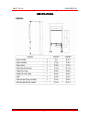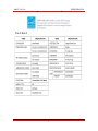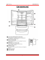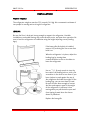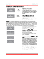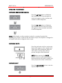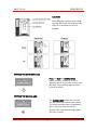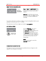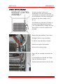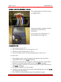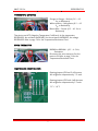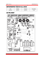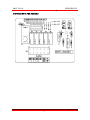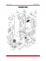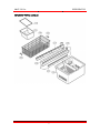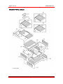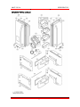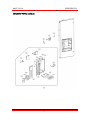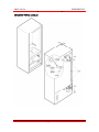
1
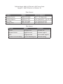
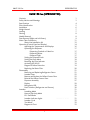
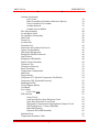
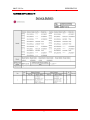
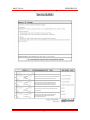
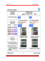
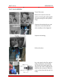
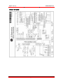
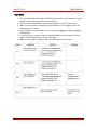
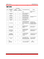
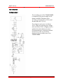
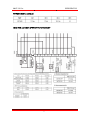
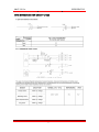
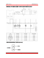
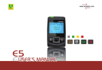
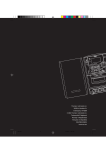
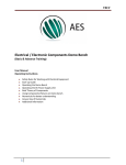
LG TRAINING MANUAL
Four Door Refrigerator LMX21981**
Fall 2008
Published August 2008 by LG Electronics USA Trainng Center
Copyright © 2008 LG Electronics of Alabama, Inc.
Phone Contacts:
Contact
Number
Hours of Operation
Customer Service
(800) 243-0000
24/7 - 365 days a year
Technical Support
(800) 847-7597
7am-7pm Mon-Fri / Sat 8-2 CST
Parts Sales
(888) 393-6484
7am-7pm Mon-Sat CST
Training Center
(256) 774-4051
8am-5pm Mon-Fri CST
Web Contacts:
Web Site
Address
Description
LG USA
www.lgusa.com
USA sales site
Customer Service
us.lgservice.com
Customer support
GCSC
aic.lgservice.com
Service center support
Customer Service Academy
www.LGCSAcademy.com
Technical training
LMX21981xx
REFRIGERATOR
LMX21981xx (REFRIGERATOR)
Contents
Safety Notices and Warnings
Specifications
Parts Identification
Installation
Weight Hazard
Leveling
Flooring
Handle Removal
Door Removal (Right and Left Doors)
Water Tube Connection
Water Line Installation Kit
Operation (Control Panel and Display)
Adjusting the Temperatures and Displays
Operating the Dispenser
Dispensing Crushed or Cubed Ice
Dispensing Water
Dispenser Light
Setting the Dispenser Lock
Setting the Door Alarm
Resetting the Filter Indicator
Activating ICE+PLUS
Diagnostic Failure Detection
Replacing the Water Filter
Disassembly
Removing and Replacing Refrigerator Doors
Icemaker Door
Remove and Replace the Pullout Freezer Door
Reinstall the Pullout Freezer Door
Dispenser Assembly
Display
Refrigerator LED
Door Switches (Refrigerator and Freezer)
Icemaker
Icemaking Mode
Harvest (Ejection) Mode
Fill / Park Mode
Icemaker Indicator Lights
080806 V. 0.99
Icemaker Cycle
Test Mode
Diagnostic Chart
LMX21981xx
Page 1
1
3
4
5
6
7
7
8
8
9
11
12
14
16
17
17
17
17
18
18
19
19
19
20
21
21
23
23
25
27
29
30
30
31
31
31
31
31
32
32
33
TRAINING MANUAL
LMX21981xx
REFRIGERATOR
Icemaker (continued)
Error Codes
Main Control Board Conductor Reference (Photo)
Power From Board To Icemaker
Icemaker Removal
Icemaker Service Bulletin
Pilot Valve Assembly
Ice and Water Valves
Fan and Motor Disassembly
News Flash
Freezer Fan
Ice Room Fan
Condenser Fan
Evaporator and Ice Room Fan Access
Freezer Section Mullion
LED Lamps (Refrigerator)
Refrigerator Module Connector
How It Works
Refrigerator LED Module
Defrost Control Assembly
Thermistor Tips
Thermistors (Sensors)
Room Thermistor
Temperature Compensation
Multi-Duct
Stepper Motor
Compressor PTC (Positive Temperature Coefficient)
Compressor OLP (Overload Protector)
Replacing the OLP
Circuit Diagram (Block)
Test Mode
Error Codes
Error Code Er rt
PCB Function
Power Circuit
Load Fan and Door Open Detection Circuit
Open Door Detection Circuit Check
Refrigeration Compartment Stepping Motor Damper Circuit
LED in Refrigerator / Freezer (Optional)
Main PWB (Layout)
Dispenser Drive PWB Assembly
Exploded Views
Temperature Resistance Chart
LMX21981xx
Page 2
33
34
35
35
37
40
41
42
42
42
43
43
43
45
45
46
46
48
50
51
52
52
52
53
54
54
55
56
57
58
59
60
61
61
62
63
64
64
65
66
67
73
TRAINING MANUAL
LMX21981xx
REFRIGERATOR
IMPORTANT SAFETY NOTICE
The information in this training manual is intended for use by persons possessing an adequate background in electrical
equipment, electronic devices, and mechanical systems. In any attempt to repair a major appliance, personal injury and
property damage can result. The manufacturer or seller maintains no liability for the interpretation of this information,
nor can it assume any liability in conjunction with its use. When servicing this product, under no circumstances should
the original design be modified or altered without permission from LG Electronics. Unauthorized modifications will not
only void the warranty, but may lead to property damage or user injury. If wires, screws, clips, straps, nuts, or washers
used to complete a ground path are removed for service, they must be returned to their original positions and properly
fastened.
CAUTION
To avoid personal injury, disconnect the power before servicing this product. If electrical power is required for
diagnosis or test purposes, disconnect the power immediately after performing the necessary checks. Also be aware
that many household appliances present a weight hazard. At least two people should be involved in the installation or
servicing of such devices. Failure to consider the weight of an appliance could result in physical injury.
ESD NOTICE
Some of the electronics in appliances are electrostatic discharge (ESD) sensitive. ESD can weaken or damage the
electronics in these appliances in a manner that renders them inoperative or reduces the time until their next failure.
Connect an ESD wrist strap to a ground connection point or unpainted metal in the appliance. Alternatively, you can
touch your finger repeatedly to a ground connection point or unpainted metal in the appliance. Before removing a
replacement part from its package, touch the anti-static bag to a ground connection point or unpainted metal in the
appliance. Handle the electronic control assembly by its edges only. When repackaging a failed electronic control
assembly in an anti-static bag, observe these same precautions.
REGULATORY INFORMATION
This equipment has been tested and found to comply with the limits for a Class B digital device, pursuant to Part 15 of
the FCC Rules. These limits are designed to provide reasonable protection against harmful interference when the
equipment is operated in a residential installation. This equipment generates, uses, and can radiate radio frequency
energy, and, if not installed and used in accordance with the instruction manual, may cause harmful interference to
radio communications. However, there is no guarantee that interference will not occur in a particular installation. If this
equipment does cause harmful interference to radio or television reception, which can be determined by turning the
equipment off and on, the user is encouraged to try to correct the interference by one or more of the following
measures: Reorient or relocate the receiving antenna; Increase the separation between the equipment and the receiver;
Connect the equipment to an outlet on a different circuit than that to which the receiver is connected; or consult the
dealer or an experienced radio/TV technician for help.
DISCLAIMER
The information in this training manual was accurate at the time of publication. Every effort has been made to ensure
accuracy. Updates, changes, etc. are available via GCSC and LGCSacademy. The information in this manual is intended
for persons with adequate backgrounds in electronics, mechanical, and electronic servicing. The manufacturer and
seller are not to be held responsible for any liability incurred from its use.
COMPLIANCE
The responsible party for this device’s compliance is LG Electronics Alabama, Inc.; 201 James Record Road, Huntsville,
AL, 35813.
LMX21981xx
Page 3
TRAINING MANUAL
LMX21981xx
REFRIGERATOR
SPECIFICATIONS
LMX21981xx
Page 4
TRAINING MANUAL
LMX21981xx
LMX21981xx
REFRIGERATOR
Page 5
TRAINING MANUAL
LMX21981xx
REFRIGERATOR
PARTS IDENTIFICATION
LMX21981xx
Page 6
TRAINING MANUAL
LMX21981xx
REFRIGERATOR
INSTALLATION
WEIGHT HAZARD!
The refrigerator weighs as much as 325 pounds (148 kg). We recommend a minimum of
two people for moving and servicing this refrigerator.
LEVELING
Be sure the floor is level and strong enough to support the refrigerator. Unstable
installation or unleveled flooring may cause vibration, noise, and poor door operation. Be
sure to level the refrigerator at installation using the height adjusting screws (leveling
legs.)
If the base grille (kick plate) is installed,
remove it by removing the two screws that
hold it on.
When the refrigerator is in place, adjust the
leveling legs by turning them
counterclockwise to raise or clockwise to
lower the refrigerator.
Use an 11/32” (8 mm) wrench to turn the
hex ends of the leveling bolts or stick a flat
screwdriver in the slots to turn them. If you
have a helper to push against the top of
the refrigerator and take the weight off the
leveling legs, you can turn them by hand.
Be sure to lower them enough to contact
the floor and support some of the weight
of the refrigerator. It will keep it from
moving when you pull the doors open and
from tipping forward when the freezer
drawer is pulled out.
Replace the base grille.
LMX21981xx
Page 7
TRAINING MANUAL
LMX21981xx
REFRIGERATOR
FLOORING
The refrigerator must be installed on a solidly constructed floor to minimize noise and
vibration. The refrigerator must be level. If necessary, adjust the leveling legs under the
front of the refrigerator to compensate for variations in the flooring. This is easier if the
refrigerator is tipped slightly backward to take the weight off the legs. Turn them
clockwise to raise the refrigerator or counterclockwise to lower it.
Never install the refrigerator on a platform or a weakly supported structure.
When moving the refrigerator for cleaning or service, be sure to protect the floor. Pull
the refrigerator straight out. Do not walk or wiggle it; floor damage or side panel damage
may occur.
HANDLE REMOVAL
It may be necessary to remove the handles
to get the refrigerator through a door.
Loosen the set screws with a 3/32”
(2.5 mm) Allen wrench.
Remove the handle.
If the mounting bolts require removal or
adjustment, use a ¼” Allen wrench.
Use extreme caution when removing the
handles to avoid scratching the doors.
When you remove or replace a handle,
push (or pull) firmly but do not damage the
handle or the door by using excessive
force.
Replace the handles by placing the handles
on the mounting bolts and tightening the
set screws.
LMX21981xx
Page 8
TRAINING MANUAL
LMX21981xx
REFRIGERATOR
DOOR REMOVAL
Disconnect the electrical supply and shut off the water to the refrigerator before
installing or servicing.
Do not put your hands, feet, fingers, or metal (conductive) items into the air vents, the
base grille (kick plate), or bottom of the refrigerator. You could be injured or shocked.
If the entrance door is too small to accommodate the refrigerator, you can remove the
doors and pull the refrigerator into the room sideways.
RIGHT REFRIGERATOR DOOR
Open the door to 90°.
Remove the top hinge cover (1) screw.
Lift the cover (2).
Disconnect the wire (3) harness.
Rotate the hinge lever (4) clockwise and
remove it.
Lift the top hinge (5) clear of the hinge
lever latch (6).
LMX21981xx
Page 9
TRAINING MANUAL
LMX21981xx
REFRIGERATOR
LEFT REFRIGERATOR DOOR
Disconnect the hose at the top right
corner (facing the back) by removing the
release clip and pressing the release ring.
The tube will be pulled out with the door
when it is removed.
Open the door to 90°.
The door must be opened to 90° to be
removed or reattached.
Remove the screw (1) securing the top
hinge cover.
Use a flat screwdriver to pry off (2) the
hinge cover. (Hooks not shown.)
Remove the cover and pull the water tube
(3) through.
Disconnect all the wiring (4) harnesses.
Remove the ground (5) screws.
Turn the hinge lever (6) counter-clockwise
and remove it.
Lift the top hinge (7) free of the latch
lever (8).
Be careful the door does not fall forward.
With the door open to 90°, lift it off the
middle hinge pin.
CAUTION!
When lifting the hinge free of the latch, be careful the door does not fall forward. After
removing the door, lay it on a blanket or other padded protective surface, with the inside
facing up.
Replacement of either door is the reverse of the way it was removed.
LMX21981xx
Page 10
TRAINING MANUAL
LMX21981xx
REFRIGERATOR
WATER TUBE CONNECTION
The water tube connections must be properly assembled to avoid leaking.
Insert the tube into the connector until
only one of the printed lines is visible.
Pull on the tube slightly to ensure proper
insertion and retention. Insert the retainer
clip under the release ring.
If you can see both rings, the tube is not
inserted properly. The tube end must be
cut squarely.
LMX21981xx
Page 11
TRAINING MANUAL
LMX21981xx
REFRIGERATOR
WATER LINE CONNECTION
Read ALL the directions thoroughly before you begin. Be certain you understand all the
requirements for installing and connecting a water connection for this refrigerator.
WARNING! Connect the water supply tube from the refrigerator to a potable water
supply only.
The water pressure requirement for this refrigerator is 43 ~ 121 psi (3 ~ 8.5 kgf/cm2).
If the existing pressure is insufficient, the customer can purchase a separate pressure
pump to provide normal ice making and water dispensing operation.
•
•
•
•
The total length of the water supply line should not be greater than 26 feet
(8 meters).
Use copper tubing or a braided, reinforced nylon supply line.
Install the water line in an area where the temperature will not drop below
freezing.
It may take up to 24 hours for the icemaker to begin producing ice.
The icemaker water valve includes a flow washer that is used as a water pressure
regulator.
TOOLS REQUIRED
Standard screwdriver
7
/16” open-end wrench
¼” drill bit
¼” nut driver
½” open end wrench
drill (electric drills must be grounded)
WATER LINE INSTALLATION KIT
Some dealers sell an installation kit that includes all the parts necessary to connect the
refrigerator to a water line. Often, these kits include a piercing saddle-type valve that
allows connection to the water line without the need for plumbing skills. LG does not
recommend the use of this type valve because it often fails to provide sufficient water
flow for the icemaker and dispenser to function properly.
continued on next page
LMX21981xx
Page 12
TRAINING MANUAL
LMX21981xx
REFRIGERATOR
Various connector types are available.
These illustrations show a saddle valve with
the water line connected using a
compression fitting at each end.
The additional coil of tubing (approximately 7 feet or 2.1 m) is to allow pulling
the refrigerator out for servicing or
cleaning.
We recommend the use of a pre-assembled
braided plastic or nylon line with threaded
couplings on both ends to prevent leakage
and pop offs.
CONNECTING THE WATER LINE
We recommend using a flare nut wrench to connect the water line fittings. After the valve
has been installed on the water line, it must be flushed before connecting it to the
refrigerator Remove the plastic cap from the water valve on the back of the refrigerator.
Attach the water supply line to the valve. Open the valve and flush out the supply line
before attaching it to the refrigerator. Attach the supply line to the water valve on the
back of the refrigerator. Tighten all connections. Turn on the water and check for leaks.
Press the water dispenser button and bleed all the air through the system. When water
begins coming out, run another quart to be sure all the air is out of the line. Turn the
icemaker on and cycle it manually until water fills the tray to ensure all the air is out of
the line.
LMX21981xx
Page 13
TRAINING MANUAL
LMX21981xx
REFRIGERATOR
OPERATION
1. LED DISPLAY
The LED display shows the temperature
settings, dispenser options, water filter,
door alarm, and locking status messages.
2. ICE TYPE BUTTON
The ICE TYPE button is used to select
Cubed Ice or Crushed Ice.
3. FREEZER BUTTON
Press the FREEZER button to adjust the
temperature in the freezer compartment.
NOTE: When pressed simultaneously with
the REFRIGERATOR button for more than
five seconds, the temperature display will
change from Fahrenheit to Celsius or vice
versa.
4. REFRIGERATOR BUTTON
Press the REFRIGERATOR button to adjust
the temperature in the refrigerator
compartment.
NOTE: When pressed simultaneously with
the FREEZER button for more than five
seconds, the temperature display will
change from Fahrenheit to Celsius or vice
versa.
5. ICE PLUS BUTTON
Press this button to turn on the ICE PLUS.
feature, which increases ice making
capabilities up to about 20 percent.
6. LIGHT/FILTER BUTTON
The LIGHT/FILTER button controls the
lamp in the dispenser. The LIGHT/FILTER
button resets the water filter replacement
indicator when the water filter has been
replaced.
7. ALARM/LOCK BUTTON
Press this button to control the door-open
alarm. Press this button to lock or unlock
all the other function buttons on the
control panel, including operation of the
dispenser.
LMX21981xx
Page 14
TRAINING MANUAL
LMX21981xx
REFRIGERATOR
THE LED DISPLAY
The LED display shows the temperature
settings, dispenser options, water filter,
door alarm, and locking status messages.
1. DISPENSER SELECTION INDICATOR
Shows that Cubed ice or Crushed Ice
selection will be dispensed when the push
switch is pressed.
2. FREEZER TEMPERATURE
Indicates the set temperature of the
freezer compartment in degrees Celsius or
Fahrenheit.
3. REFRIGERATOR TEMPERATURE
Indicates the set temperature of the
refrigerator compartment in degrees
Celsius or Fahrenheit.
4. ICE PLUS
When the ICE PLUS button is pressed,
the display will indicate the selected
function has been activated.
5. DISPENSER LIGHT INDICATOR
When the LIGHT button is pressed,
the display will indicate the selected
function. When the dispenser light is on,
this indicator will appear on the display
panel.
6. DOOR ALARM INDICATOR
This indicator shows that the door-open
warning alarm is activated.
7. WATER FILTER STATUS
This indicator shows the current status for
the water filter. See Resetting the Filter
Indicator.
8. LOCK STATUS
This indicator shows the current status for
the control panel functions is set to LOCK.
LMX21981xx
Page 15
TRAINING MANUAL
LMX21981xx
REFRIGERATOR
ADJUSTING THE TEMPERATURE AND DISPLAYS
Adjust Freezer Temperature
To adjust the temperature in the freezer
compartment, press the FREEZER button
to cycle through the range of available
settings.
Adjust Refrigerator Temperature
To adjust the temperature in the
refrigerator compartment, press the
REFRIGERATOR button to cycle through
the range of available settings.
NOTE: The actual inner temperature varies depending on the food status, since the
indicated temperature setting is the target temperature and not the actual temperature
within the refrigerator. Initially set the REFRIGERATOR CONTROL at 37 degrees F and
the FREEZER CONTROL at 0 degrees F. Leave them at these setting for 24 hours (one
day) to stabilize. Then adjust the compartment temperature as illustrated above.
To change the temperature display from
Fahrenheit to Celsius or vice versa,
simultaneously press and hold the
FREEZER and REFRIGERATOR buttons for
more than 5 seconds.
Display Power-Saving Mode
This function places the display into the
Power-Saving Mode.
Simultaneously press the FREEZER and ICE
PLUS buttons and hold them for 5 seconds
until a tone sounds. All LED lights will turn
on and then off. When the Power-Saving
Mode is activated, the display will remain
off until the next time the door is opened.
The display will also turn on when any
button is pressed, and it will remain on for
20 seconds after the last door opening or
button selection.
To deactivate the Power-Saving Mode,
press the FREEZER and ICE PLUS buttons
simultaneously and hold them for 5
seconds until the tone sounds.
LMX21981xx
Page 16
TRAINING MANUAL
LMX21981xx
REFRIGERATOR
OPERATING THE DISPENSER
DISPENSING CRUSHER OR CUBED ICE
Press the ICE TYPE button to illuminate
the Crushed Ice icon. Press the push ice
switch with a glass or other container and
crushed ice will be dispensed.
Press the ICE TYPE button to illuminate
the Cubed Ice icon. Press the push switch
with a glass or other container and cubed
ice will be dispensed.
NOTE: Hold the glass or other container in place for a couple of seconds after
dispensing ice or water to catch the last few cubes or drops. The dispenser is designed to
not operate while either refrigerator door is open.
DISPENSING WATER
Press the push water switch or active water
button with a glass or other container and
chilled water will be dispensed. When the
water switch or active water switch is
pressed, the light will be illuminated.
NOTE: When operating the WATER
button; it does not work when you press
both ends and not the center. It works only
when you press the center of the button.
DISPENSER LIGHT
Press the LIGHT/FILTER button to turn the
dispenser light on and off.
LMX21981xx
Page 17
TRAINING MANUAL
LMX21981xx
REFRIGERATOR
CAUTION
When filling the container with a small
opening, use it near the opening of the
water or ice dispenser as close as
possible.
SETTING THE DISPENSER LOCK
Press and hold the ALARM/LOCK
button for three seconds to lock the
dispenser and all of the other control panel
functions. Press and hold again for three
seconds to unlock.
SETTING THE DOOR ALARM
The ALARM/LOCK button also controls
the door alarm that sounds three times in
30-second intervals when a compartment
door is left open for more than 60
seconds. The alarm stops sounding when
the door is closed.
LMX21981xx
Page 18
TRAINING MANUAL
LMX21981xx
REFRIGERATOR
RESETTING THE FILTER INDICATOR
Press and hold the LIGHT/FILTER button
for more than 3 seconds to reset the filter
indicator after the water filter has been
replaced.
NOTE: Replace the filter when the water
filter indicator light reaches 0 or whenever
the water or ice cube taste deteriorate
noticeably.
To purchase replacement water filter cartridges, visit your local appliance dealer or parts
distributor. You can also call 1-877-714-7486.
The replacement water filter cartridge’s part number is 5231JA2006A.
ACTIVATING ICE PLUS
Press the ICE+PLUS button once to
activate the ICE+PLUS function.
The ICE+PLUS icon on the display panel
will illuminate when activated.
The ICE+PLUS function runs the freezer
compartment at the coldest setting for a
24-hour period to increase icemaking by
up to about 20%, and then turns off
automatically.
NOTE:
Press the button again to cancel the
ICE+PLUS function.
DIAGNOSTIC FAILURE DETECTION
The diagnostic function automatically detects problems with your refrigerator, and a
diagnostic code will appear in the display.
LMX21981xx
Page 19
TRAINING MANUAL
LMX21981xx
REFRIGERATOR
REPLACING THE WATER FILTER
Replace the filter when the water filter indicator decrements to 0 or the water dispenser
or icemaker noticeably decrease production.
Rotate the knob of the old cartridge
counterclockwise. When the cartridge is
released, you will feel it click out of place.
NOTE: Replacing the filter causes a small
amount of water (around 1 oz. or 25 cc)
to drain. Place a cup under the filter hole
to contain it.
Remove the old cartridge. Take the new
cartridge out of its packaging, and remove
the protective cover from the o-rings. Hold
the cartridge handle in its vertical position,
and firmly push the new filter cartridge into
place until it stops.
Use the handle to twist the cartridge
clockwise about one turn, until the handle
is in a horizontal position. You will feel the
filter click into place.
NOTE: If the filter will not turn from side to
side, it isn’t fully inserted.
After replacing the filter, dispense for 2
minutes from the water dispenser to purge
the water system. Check the filter for leaks.
When the water filter indicator displays the message 0 Filter Month, Hold 3 Seconds,
reset the water filter status display and indicator light by pressing and holding the
LIGHT/FILTER button for more than 3 seconds.
LMX21981xx
Page 20
TRAINING MANUAL
LMX21981xx
REFRIGERATOR
DISASSEMBLY
REMOVING AND REPLACING REFRIGERATOR DOORS
CAUTION: Before you begin, unplug the refrigerator. Remove food and bins from doors.
Left Door – FIGURE 2 (Next Page)
1.
2.
3.
4.
5.
6.
Disconnect water supply tube by pushing back on the disconnect ring (4).
See FIGURE 1, next page.
Open the left door. Loosen the top hinge cover screw (1). Use a flat tip
screwdriver to pry back the hooks on the front underside of cover (3).
Lift up the cover.
Disconnect the door switch wire harness (2). Remove the cover.
Pull out the tube.
Disconnect the three wire harnesses (5). Remove the grounding screw (6).
Rotate hinge lever (7) counterclockwise and remove. Lift the top hinge (8) free of
the hinge lever latch (9).
CAUTION:
7.
When lifting the hinge free of the latch, be careful that the door does not
fall forward.
Place the door, inside facing up, onto a non-scratching surface.
Right Door – FIGURE 3 (Next Page)
1.
2.
3.
4.
Open the door. Loosen the top hinge cover screw (1). Lift up the cover (3).
Disconnect the door switch wire harness (2). Remove the cover.
Disconnect the wire harness (5).
Rotate the hinge lever (6) clockwise and remove. Lift the top hinge (7) free of the
hinge lever latch (8).
CAUTION:
5.
6.
When lifting the hinge free of the latch, be careful that the door does not
fall forward.
Lift door the up from middle hinge pin (9) and remove the door.
Place the door, inside facing up, onto a non-scratching surface.
See drawings, next page.
LMX21981xx
Page 21
TRAINING MANUAL
LMX21981xx
LMX21981xx
REFRIGERATOR
Page 22
TRAINING MANUAL
LMX21981xx
REFRIGERATOR
ICEMAKER DOOR
Loosen the front screw (nearest the hinge)
of the bracket.
Lift the hinge with one hand. It might be
necessary to loosen the rear screw slightly.
Lift the icemaker door out of the lower
hinge with the other hand.
REMOVE and REPLACE the PULLOUT FREEZER DRAWER
Open the freezer door.
Remove the lower basket.
LMX21981xx
Page 23
TRAINING MANUAL
LMX21981xx
REFRIGERATOR
PULLOUT FREEZER DRAWER, continued
Remove the two screws from the guide rails
(one from each side.)
Lift the freezer door up to unhook it from
the rail support and remove.
Pull both rails to full extension.
Remove the gear from the left side first by
releasing the tab behind the gear, place a
screwdriver between the gear and the tab
and pull up on the gear.
Remove the center rail.
Remove the gear from the right side by
following the same steps for the left side.
NOTE: THIS TAB MUST BE PUSHED IN
TO RELEASE THE GEAR.
LMX21981xx
Page 24
TRAINING MANUAL
LMX21981xx
REFRIGERATOR
FOLLOW THESE STEPS TO REINSTALL
Reinstall the right side gear into the clip.
Insert the rail into the right side gear. The
gears do not need to be perpendicular to
each other.
Insert the rail into the left side gear, and
insert the gear into the clip.
continued on next page
LMX21981xx
Page 25
TRAINING MANUAL
LMX21981xx
REFRIGERATOR
REINSTALLATION, continued
The rail system will align itself by pushing
the rails all the way into the freezer
section. Pull the rails back out to full
extension.
Reinstall the freezer door by inserting the
rail tabs into the guide rail.
Reinstall the two screws into the guide rails
(one from each side).
Reinstall the lower basket, and close the
freezer door.
LMX21981xx
Page 26
TRAINING MANUAL
LMX21981xx
REFRIGERATOR
DISPENSER ASSEMBLY
Remove the tray. Lift out the grate.
Then pull the tray out past the stops
without breaking it.
NOTE: Pay close attention to the clip that
is located under the tray. Look at how it is
installed in case it comes out while
removing the dispenser assembly.
Remove the tray.
Lift out the grate.
Then pull the tray out past the stops
without breaking it.
Release the lower clips.
LMX21981xx
Page 27
TRAINING MANUAL
LMX21981xx
REFRIGERATOR
DISPENSER ASSEMBLY, continued
Release the side clips.
Loosen all four edges.
Pull the dispenser assembly forward and
remove all the connectors.
LMX21981xx
Page 28
TRAINING MANUAL
LMX21981xx
REFRIGERATOR
DISPENSER ASSEMBLY, continued
Back view of dispenser.
Display PCB.
DISPLAY
WHITE/BLACK – 12VDC to Display Board
BRIGHT ORANGE – Ground
BROWN – RX (RX to Ground Receives
Variable VDC Pulse)
RED – TX (TX to Ground Transmits
Variable VDC Pulse)
LMX21981xx
Page 29
TRAINING MANUAL
LMX21981xx
REFRIGERATOR
REFRIGERATOR LED
BLUE/WHITE – 12VDC from Refrigerator
Door Switch (CON 5)
BLU/WH to PK(CON 6) or BOR
Door CLOSED – 0 VDC
Door OPEN – 12 VDC
BLUE/WHITE – 12VDC from PC to WHITE
on LED (CON 4)
BLUE/WH to PK(CON 6) or BOR
Door CLOSED – 0 VDC
Door OPEN - 12VDC
REFRIGERATOR DOOR SWITCH
GRAY to GRAY – N.C. Switch – Door
OPEN, Switch CLOSED (CON 4)
Door CLOSED – 4.5 VDC
Door OPEN – 0 VDC
This is a monitoring circuit.
FREEZER DOOR SWITCH
Brown to Brown – N.C. Switch – Door
Closed, Switch is OPEN (CON 6)
0 VDC – Door OPEN
4.5 VDC – Door CLOSED
This is a monitoring circuit.
LMX21981xx
Page 30
TRAINING MANUAL
LMX21981xx
REFRIGERATOR
ICEMAKER
ICEMAKING MODE
The icemaking cycle begins with the water fill operation. When the water is frozen, as
determined by a sensor incorporated in the tray, the cubes are ejected, and the process
is repeated. The sensor triggers the cycle when it reaches 16 to 19° F (-7° C),
approximately 55 minutes after the start of the cycle.
HARVEST (EJECTION) MODE
Harvest (ejection) occurs at the end of the cycle when the ice is released from the mold
and pushed into the bin. When harvest mode begins, the mold heater operates for 30
seconds; then the motor starts. The feeler arm senses the amount of ice while the ejector
rotates. If the bin is full, the heater is turned off and the ejector stops. If the bin is not
full, the ejector rotates two turns to eject the ice and begin a new cycle. If the ejector
does not rotate at least one full turn within five minutes, a separate heater control mode
activates to prevent damage to the icemaker.
FILL / PARK MODE
After the harvest mode is complete, the water valve is opened to fill the mold for the next
cycle. The amount of water is related to the water pressure, but can be adjusted by
changing the time for which the valve is opened. With the icemaker turned on, press the
button to increase the size of the cubes to the next available size. Subsequent presses
will cycle through all available sizes.
ICEMAKER INDICATOR LIGHTS
LMX21981xx
Page 31
TRAINING MANUAL
LMX21981xx
REFRIGERATOR
ICEMAKER CYCLE
TEST MODE
Press and hold the cube size button for more than three seconds to put the icemaker
into test mode. The test cycle can be used to diagnose icemaker issues and to clean it.
The test mode can be started only in ice making mode; it cannot be accessed while the
icemaker is filling or ejecting. Press and hold the cube size button for more than three
seconds to put the icemaker into test mode.
The test cycle can be used to diagnose icemaker issues and to clean it.
The test mode can be started only in ice making mode; it cannot be accessed while the
icemaker is filling or ejecting.
CAUTION!
If the icemaker is cycled through test mode before the water already in it has frozen, the
ejector will pass through the water and any added water will cause the mold to overflow.
LMX21981xx
Page 32
TRAINING MANUAL
LMX21981xx
REFRIGERATOR
If the icemaker does not operate normally during test mode, turn it off. Check it and
repair as necessary or replace.
When the test cycle is complete, the icemaker reverts to MICOM control and assumes
the factory default fill setting.
DIAGNOSTIC CHART
ERROR CODES
LMX21981xx
Page 33
TRAINING MANUAL
LMX21981xx
REFRIGERATOR
MAIN CONTROL BOARD CONNECTOR REFERENCE
LMX21981xx
Page 34
TRAINING MANUAL
LMX21981xx
REFRIGERATOR
POWER from BOARD to ICEMAKER
RED – 120VAC supply to icemaker fill valve
in the door (when activated)
BLUE – Constant neutral
YELLOW – Constant 120VAC supply to
icemaker and refrigerator door
BLACK – 120 VAC to compressor
(when activated)
GREY – 120 VAC to water dispenser pilot
valve (rear) (when activated)
WHITE – 120 VAC to defrost circuit
(when activated)
BROWN – 120 VAC to heaters
(pulsing OFF & ON)
BLUE – Neutral (constant)
RED – 120 VAC to icemaker pilot valve
(rear) (when activated)
ICEMAKER REMOVAL
Remove five AC motor assembly screws.
Remove the entire icemaker assembly.
LMX21981xx
Page 35
TRAINING MANUAL
LMX21981xx
REFRIGERATOR
ICEMAKER REMOVAL, continued
Separate the two electrical connectors.
Remove the upper screws.
Remove the ground screw. Replace it in the
icemaker assembly in the event you need
to reuse it or require it in the replacement
unit.
Separate the 4-pin electrical connector.
LMX21981xx
Page 36
TRAINING MANUAL
LMX21981xx
REFRIGERATOR
ICEMAKER SERVICE BULLETIN
LMX21981xx
Page 37
TRAINING MANUAL
LMX21981xx
LMX21981xx
REFRIGERATOR
Page 38
TRAINING MANUAL
LMX21981xx
LMX21981xx
REFRIGERATOR
Page 39
TRAINING MANUAL
LMX21981xx
REFRIGERATOR
PILOT VALVE ASSEMBLY
Turn off the water.
Remove the water line from the
valve by removing the release guard
clip and pressing the collet (release
ring.)
Separate the mechanical cover and
remove the screw that holds the
valve assembly to the refrigerator.
Separate the housing.
Pull out the valve.
Lay a dry towel on the floor and be
ready to spill water from the filter
line. Remove the release guard clip
and press the collet to separate the
tube from the connector. Allow the
water to drain from the line until it is
empty.
LMX21981xx
Page 40
TRAINING MANUAL
LMX21981xx
REFRIGERATOR
ICE AND WATER VALVES
Remove the tilt drawer (door bin.)
Remove the valve access panel.
Reservoir (tubing) and valves.
Ice and water valves.
LMX21981xx
Page 41
TRAINING MANUAL
LMX21981xx
REFRIGERATOR
FAN and MOTOR DISASSEMBLY
Using a short screwdriver, loosen one
screw in the drain pipe assembly and
another one connected to the motor cover.
Pull the fan blade off its shaft by turning it
counterclockwise as you pull.
NEWS FLASH
The fan motor is a variable speed DC motor. If it becomes jammed, it will try to start
every thirty seconds for five minutes, and then once every thirty minutes. The input
voltage and signal voltages are measurable.
To clear the ER error code, unplug, repair, and replace the fan motor. Or, if you wait
thirty minutes, the situation will clear itself.
The fan speed is controlled by the sensor temperature. If the signal is interrupted, the
motor will run for five minutes. After that time, the fan will stop and an error code will be
displayed.
FREEZER FAN
WHITE – SUPPLY (Positive)
BLACK – GROUND
PURPLE - SIGNAL (Positive)
V = Voltage
G = Ground
F = Feedback
LMX21981xx
While operating:
WH to BLK – Approx. 13.9 VDC
(15 VDC during ICE+PLUS)
PR to BLK – Approx. 2 VDC
Door OPEN or OFF – 0 VDC
Page 42
TRAINING MANUAL
LMX21981xx
REFRIGERATOR
ICE ROOM FAN
RED – SUPPLY (Positive)
BLUE – GROUND
BROWN – SIGNAL (Positive)
While Operating:
RD to BL – Approx. 11.1 VDC
BL to BR – 2.5 VDC
Door OPEN or OFF – 0 VDC
CONDENSER FAN
SKY BLUE – SUPPLY (Positive)
BRIGHT ORANGE – GROUND
YELLOW – SIGNAL – (Positive)
While operating:
SB to BO – Appox. 11.1 VDC
Y to BO – 2.5 VDC
Door OPEN or OFF – 0 VDC
EVAPORATOR and ICE ROOM FAN ACCESS
Remove the top drawer rails.
LMX21981xx
Page 43
TRAINING MANUAL
LMX21981xx
REFRIGERATOR
EVAPORATOR and ICE ROOM FAN ACCESS, continued
Release the tabs on the back panel and pull
the panel out toward you.
Separate the connectors and you can
remove the entire panel assembly from the
freezer.
NOTE:
The ice room fan supplies air to the ice
room through ducting in the cabinet.
Where the door meets the cabinet, there
are gaskets to seal the ducts between
them, allowing the air to go into the ice
room. The air supply enters through the
top and the return is on the bottom.
LMX21981xx
Page 44
TRAINING MANUAL
LMX21981xx
REFRIGERATOR
FREEZER SECTION MULLION
The service manual makes no reference to
this loop. It would be very easy for a
technician to break these refrigerant lines
when attempting to access the fan motors
or defrost components.
CAUTION : DO NOT ATTEMPT TO
REMOVE THE MULLION; IT CONTAINS
REFRIGERANT LINES!
Yoder line heater in mullion (black lines.)
The rear panel can be easily removed after
removing the left and right upper door
supports. The panel can then be slid
through the upper door opening above the
mullion!
LED LAMPS (REFRIGERATOR)
If necessary, unload remove the top
shelves.
Remove the two screws.
Grasp both ends of the lamp assembly and
pull it down and out of the cavity.
Use a flat screwdriver to remove the cover
lamp.
Separate the LED assembly and the cover.
LMX21981xx
Page 45
TRAINING MANUAL
LMX21981xx
REFRIGERATOR
REFRIGERATOR MODULE CONNECTOR
HOW IT WORKS
On this new 4-door refrigerator, the LED
control board has been incorporated into
the main PWB Assembly. The operation
and diagnosis is easier than previous
refrigerators with a separate LED control
board assembly.
This refrigerator has 2 LED modules, one in
the refrigerator section and one in the
freezer section. They are labeled R-Room
LED Module and F-Room LED Module. Each
door of this refrigerator has a door switch.
Each door switch is 2 switches in one.
These door switches have 2 single pole,
single throw normally closed (NC)
switches. The door open perception switch,
shown in CON 4, pins 11 and 12, is a
5 VDC refrigerator door monitoring switch.
Notice the wire colors connecting these
terminals to the refrigerator door switches
are gray (GY). These gray wires attach to
terminals H & I, shown on the R-Door
switch above.
NOTE: Only 1 refrigerator door switch is shown in the wiring diagram. There are two
refrigerator door switches, one for each door, both wired as shown above. Likewise, in
CON 6, pins 5 and 6 these brown (BN) wires connect the 2 freezer door switches on
connectors F & G. These are also 5 VDC door monitoring switches.
LMX21981xx
Page 46
TRAINING MANUAL
LMX21981xx
REFRIGERATOR
HOW IT WORKS, continued
Operationally, the door monitoring switches are open when the doors are closed. When
doors are closed and monitoring switches for the refrigerator and freezer doors are open,
5 VDC will be measured across the control board terminals referenced above and 5 VDC
will be measured across the open terminals of the perception section of the door
switches. When the door or doors are open, the switches will be closed. When this occurs,
zero (0) VDC will be measured across the door perception terminals on the control board
and across the perception terminals of the door switches.
The LED section operates on 12 VDC from CON 6, pins 15, 14, and 13. Pin 15 (PK) is
marked (D); this terminal is the ground reference for measuring the 12 VDC in the LED
section of the control board. Pin 14 (GY) is marked (E) and is the 12 VDC output to both
LED Modules in the refrigerator and freezer sections.
Looking closely at the LED Modules, you will see that (E) is connected to Pin 1 on the
LED Modules. This RD lead is the 12 VDC from the control board pin 14 (GY). Pin 2 on
the LED Module is marked (D) from the control board and is a BK wire, which is the
ground reference from Pin 15 (PK). 12 VDC should be present at ALL times on pins 1 and
2, RD to BK on both LED modules. This 12 VDC will be used to operate the LEDs in each
module when the signal voltage arrives on Pin 3 (WH).
Pin 13 (SB) on CON 6 of the main power board is a 12 VDC output going to each door
switch in the refrigerator and freezer sections. The 2nd switch in each door switch
supplies this 12 VDC when the door is open to the LED Modules terminal 3 (WH). When
12 VDC is measured on the LED module of the refrigerator or freezer from BK to WH the
LEDs will turn on. (Note: Remember there must be 12 VDC from BK to RD also!)
Look closely again at the refrigerator door switch. (Remember there are actually 2 of
these switches, 1 for each refrigerator door, wired as the diagram shows!) When either
refrigerator door is opened, 12 VDC from SB to BL/WH is sent to CON 5, pin 7 on the
main control power board. A jumper is placed on the board from CON 5, pin 7 to CON 4,
pin 1 (BL/WH). With the refrigerator door open, the 12 VDC leaves CON 4, pin 1
(BL/WH) and connects to the white (WH) wire on pin 3 of the refrigerator LED Module.
As with the freezer LED Module, when 12 VDC is present on pin 3 (WH) the LEDs will
turn on!
FINAL REMINDER: All LED DC voltages on the main power board are referenced
(measured) from CON 6, pin 15 (PK). Pin 15 is the ground reference terminal. Likewise,
on the LED modules, pin 2 (BK) is the ground reference when measuring DC voltages to
pins 1 and 3.
LMX21981xx
Page 47
TRAINING MANUAL
LMX21981xx
REFRIGERATOR
REFRIGERATOR LED MODULE
White to Black
Door closed
0 VDC
White to Black
Door open
12 VDC
LMX21981xx
Page 48
TRAINING MANUAL
LMX21981xx
REFRIGERATOR
REFRIGERATOR LED MODULE, continued
Red to Black
12 VDC Constant
The freezer LED assembly is similar to the
refrigerator, but smaller. The repair
procedure is the same.
SKY BLUE – 12 VDC supply to all LED
door switches WHITE Wires
GRAY – 12 VDC supply to all LED
modules RED Wires
PINK – Negative to all LED door switches
BLACK wires
LMX21981xx
Page 49
TRAINING MANUAL
LMX21981xx
REFRIGERATOR
DEFROST CONTROL ASSEMBLY
The defrost sensor consists of a
temperature sensor and a thermal fuse.
This assembly is attached to the metal side
of the evaporator and senses temperature.
It turns off the defrost heater at 46 °F
(8° C).
The thermal fuse (Fuse-M) is for safety to
prevent overheating during the defrost
cycle. The thermal fuse is a single-use item;
when it blows, it must be replaced as an
assembly.
Remove the grille assembly in the freezer.
Unplug the defrost control assembly.
Cut the tie-wrap that holds it in place.
Remove and replace the assembly.
Secure it with a new tie-wrap.
Plug in the new assembly and replace the
grille.
In the two photos to the left, the orange
leads are the defrost sensor.
The blue and brown leads are the fuse link.
LMX21981xx
Page 50
TRAINING MANUAL
LMX21981xx
REFRIGERATOR
DEFROST CONTROL ASSEMBLY, continued
The orange leads go to the defrost sensor
on CONNECTOR 6.
Using your ohmmeter, read the resistance
of the sensor to determine the
temperature.
In this example, 60.5 kΩ indicates 5° F.
(See thermistor chart, page 74.)
THERMISTOR TIPS
•
•
•
•
The icemaker cycles at 16° F.
The ice room fan cycles on at +6° F and off at +2° F.
The defrost cycle terminates at 46° F (8° C)
There is no defrost cycle if the internal temperatures are above 46° F.
If a sensor fails:
•
•
•
•
•
•
The refrigerator sensor cycles the damper and evaporator fan every fifteen
minutes while the error code Er rS is displayed.
The freezer sensor cycles the compressor, evaporator fan motor, and condenser
fan motor every fifteen minutes while the error code Er FS is displayed.
The ice room sensor cycles the ice room fan every fifteen minutes while the error
code Er IS is displayed.
The ice sensor will NOT cycle the icemaker.
The defrost cycle terminates after one hour. After displaying the error code Er dH,
the cooling operation resumes.
Error codes are cleared immediately upon the completion of repairs.
LMX21981xx
Page 51
TRAINING MANUAL
LMX21981xx
REFRIGERATOR
THERMISTORS (SENSORS)
Orange to Orange – Defrost (0.5 – 4.5
VDC or Resistance)
White to White – Refrigerator (0.5 – 4.5
VDC or Resistance)
Blue to Blue – Freezer (0.5 – 4.5 VDC or
Resistance)
Thermistors are NTC (Negative Temperature Coefficient). As the temperature
DECREASES, the resistance INCREASES. As the resistance INCREASES, the voltage
DECREASES. Refer to page 74 for the Temperature/Resistance Chart.
ROOM THERMISTOR
BROWN to BROWN – (0.5 – 4.5 VDC)
Resistance:
Disconnect the wire connector. Set the
meter to Ω. Refer to page 74 for the
Temperature/Resistance Chart.
TEMPERATURE COMPENSATION
Opening jumpers JCR1and 2 will increase
the refrigerator temperature by 1ºC each.
Opening jumpers JCR3 and 4 will decrease
the refrigerator temperature by1ºC each.
1°C = 1.8° F
LMX21981xx
Page 52
TRAINING MANUAL
LMX21981xx
REFRIGERATOR
MULTI-DUCT
Pry out the upper and lower caps and
remove the two screws.
Separate the electrical connectors when
the duct is removed.
Replace the foam gasket if it is damaged.
Be sure the newly adhered gasket does not
interfere with damper operation.
Store the duct where it will not be
damaged or crushed during repairs.
Replacement is the reverse of this
procedure.
LMX21981xx
Page 53
TRAINING MANUAL
LMX21981xx
REFRIGERATOR
STEPPER MOTOR
Blue to Black – Pulsing mVDC @ 75Hz
while operating (400 Ω)
Yellow to Red – Pulsing mVDC @ 75Hz
while operating (400 Ω)
120 VAC loads switching relays
COMPRESSOR PTC (Positive Temperature Coefficient)
The PTC (Positive Temperature
Coefficient) is a non-contact ceramic
semiconductor that uses BaTiO3. The
resistance increases as the temperature
increases. This part is attached to the
compressor case and used to start the
compressor and to prevent starting when
conditions require. The compressor is a
single-phase induction motor.
The PTC allows current to energize both
the start and main windings to start the
motor.
LMX21981xx
Page 54
TRAINING MANUAL
LMX21981xx
REFRIGERATOR
The PTC must be allowed to cool before the system can be restarted. Within the sealed
system, it takes approximately 5 minutes for the pressure to equalize so the compressor
can restart. When the PTC cools sufficiently, the compressor can start again. If the
compressor attempts to restart before the PTC has cooled, the PTC will allow current to
flow to only the main winding and the OLP will open because of the over current
condition. This process will repeat itself 3 to 5 times while the compressor tries to
restart until the PTC cools sufficiently.
It is critical to use the correct parts when replacing the OLP and PTC or the compressor
will be damaged. Parts may appear physically identical but could have different electrical
ratings.
Order replacement parts by model number and serial number.
OVERLOAD PROTECTOR (OLP)
The OLP (Over Load Protector) is attached to the outside of the compressor and
protects it by opening the circuit if the temperature exceeds the operating limit. When
high current flows to the compressor, the heater inside the OLP causes the bimetal
spring to expand, interrupting the current to the compressor.
Do not adjust the OLP in any manner.
LMX21981xx
Page 55
TRAINING MANUAL
LMX21981xx
REFRIGERATOR
REPLACING THE OLP
Remove the rear cover of the refrigerator
to expose the
compressor and mechanical area.
Remove the two screws on the retaining
clamp of the compressor.
Loosen two screws on the compressor
base.
Use a flat screwdriver to pry off the cover.
Remove and replace the OLP and the PLC.
(These should be replaced as a set.)
Replace the cover and tighten all screws
loosened.
LMX21981xx
Page 56
TRAINING MANUAL
LMX21981xx
REFRIGERATOR
CIRCUIT DIAGRAM
LMX21981xx
Page 57
TRAINING MANUAL
LMX21981xx
REFRIGERATOR
TEST MODE
1. The test mode allows checking the PCB and the function of the product as well as
finding out the defective part in case of an error.
2. The test mode is operated by pressing test button at main PCB controller.
3. While in the test mode, the function control button is not recognized, but the
recognition tone sounds.
4. After exiting the test mode, be sure to reset by unplugging and then plugging in
the appliance.
5. If an error, such as a sensor failure, is detected while in the test mode, the test
mode is cleared and the error code is displayed.
6. While an error code is displayed, the test mode will not be activated.
LMX21981xx
Page 58
TRAINING MANUAL
LMX21981xx
REFRIGERATOR
ERROR CODES
LMX21981xx
Page 59
TRAINING MANUAL
LMX21981xx
REFRIGERATOR
ERROR CODE Er rt
The error code Er rt will show on the
display at the beginning of the test mode
if there is a defective ambient sensor
reading.
Otherwise, it will not be seen by the
customer and does not affect normal
operation of the refrigerator.
LMX21981xx
Page 60
TRAINING MANUAL
LMX21981xx
REFRIGERATOR
PCB FUNCTION
POWER CIRCUIT
The secondary part of the TRANSFORMER
is composed of the power supply for the
display, the BLDC FAN Motor drive
(15.5 VDC), the relay drive (12 VDC) and
the MICOM and IC (5 VDC).
The voltage for each part is as follows:
VA1 is a part for preventing over voltage
and noise. When 230 V or higher power is
applied, the inside elements are short
circuited and broken, resulting in blowout
of the fuse in order to protect the
elements of the secondary part of the
TRANSFORMER.
LMX21981xx
Page 61
TRAINING MANUAL
LMX21981xx
REFRIGERATOR
POWER CIRCUIT, continued
LOAD FAN and DOOR OPEN DETECTION CIRCUIT
LMX21981xx
Page 62
TRAINING MANUAL
LMX21981xx
REFRIGERATOR
OPEN DOOR DETECTION CIRCUIT CHECK
LMX21981xx
Page 63
TRAINING MANUAL
LMX21981xx
REFRIGERATOR
REFRIGERATION COMPARTMENT STEPPING MOTOR DAMPER CIRCUIT
LED IN REFRIGERATOR / FREEZER (Optional)
LMX21981xx
Page 64
TRAINING MANUAL
LMX21981xx
REFRIGERATOR
LED IN REFRIGERATOR / FREEZER (Optional), continued
MAIN PWB ASSEMBLY
LMX21981xx
Page 65
TRAINING MANUAL
LMX21981xx
REFRIGERATOR
DISPENSER DRIVE PWB ASSEMBLY
LMX21981xx
Page 66
TRAINING MANUAL
LMX21981xx
REFRIGERATOR
EXPLODED VIEWS
LMX21981xx
Page 67
TRAINING MANUAL
LMX21981xx
REFRIGERATOR
EXPLODED VIEWS, continued
LMX21981xx
Page 68
TRAINING MANUAL
LMX21981xx
REFRIGERATOR
EXPLODED VIEWS, continued
LMX21981xx
Page 69
TRAINING MANUAL
LMX21981xx
REFRIGERATOR
EXPLODED VIEWS, continued
LMX21981xx
Page 70
TRAINING MANUAL
LMX21981xx
REFRIGERATOR
EXPLODED VIEWS, continued
LMX21981xx
Page 71
TRAINING MANUAL
LMX21981xx
REFRIGERATOR
EXPLODED VIEWS, continued
LMX21981xx
Page 72
TRAINING MANUAL
LMX21981xx
REFRIGERATOR
EXPLODED VIEWS, continued
LMX21981xx
Page 73
TRAINING MANUAL
LMX21981xx
REFRIGERATOR
TEMPERATURE RESISTANCE CHART
LMX21981xx
Page 74
TRAINING MANUAL
Four Door Refrigerator - Fall 2008