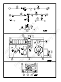
1
M
N an
or ua
th l
Pr
w Co
e
i
st m
ht nte
tp d
R plim
V
:// F
en
w ro
S
w m
up ts
w
pl o
.n
y f
w
rv
su
pp
ly
.c
om
Service Manual
For model N260 - a 2.4 cu. ft., 2-way refrigerator.
For model N260.3 - a 2.4 cu. ft., 3-way refrigerator.
NORCOLD, Inc.
P.O. Box 4248
Sidney, OH 45365-4248
Part No. 619260A (4-98)
Table of Contents
Safety Awareness
Introduction .............................................................................. 2
Safety Awareness .................................................................... 2
Safety Instructions ................................................................... 2
Specifications ........................................................................... 3
Operating limits ........................................................................ 3
Ratings .............................................................................. 3
Current draws ................................................................... 3
Replacement fuses (refrigerator control panel) ............... 3
Ventilation Requirements ........................................................ 4
LP Gas Components ............................................................... 4
Examine the LP gas supply system for leaks .................. 4
Electrical Components ............................................................. 5
Examine the 120 volts AC supply .................................... 5
Examine the 12 volts DC supply (3-way models) ............ 5
Controls .................................................................................... 5
Ignition and Start Up ................................................................ 6
Ignition - LP gas operation ............................................... 6
Start up - AC electric operation ........................................ 6
Start up - DC electric operation (3-way models) .............. 6
Shut down ......................................................................... 6
Battery drain ..................................................................... 6
Refrigerator Maintenance ........................................................ 6
Gas flame appearance ..................................................... 6
Remove and clean the burner orifice ............................... 6
Diagnosing Cooling Problems ................................................. 7
Wiring Pictorial ......................................................................... 7
Wiring Diagram ........................................................................ 7
Troubleshooting Charts ........................................................... 8
Refrigerator will not operate on AC .................................. 8
Refrigerator will not operate on DC (3-way models) ........ 9
Burner ignites but does not maintain flame ................... 10
Part Replacement .................................................................. 11
Selector switch ............................................................... 11
Thermostat ..................................................................... 11
AC heater ....................................................................... 11
DC heater (3-way models) ............................................. 11
Thermocouple ................................................................. 12
Thermocouple interrupter ............................................... 12
Gas safety valve ............................................................. 12
Read this manual carefully and understand the contents
before you install and operate the refrigerator.
Be aware of possible safety hazards when you see the safety
alert symbol on the refrigerator and in this manual. A signal
word follows the safety alert symbol and identifies the danger
of the hazard. Carefully read the descriptions of these signal
words to fully know their meanings. They are for your safety.
WARNING: This signal word identifies a hazard,
M
N an
or ua
th l
Pr
w Co
e
i
st m
ht nte
tp d
R plim
V
:// F
en
w ro
S
w m
up ts
w
pl o
.n
y f
w
rv
su
pp
ly
.c
om
which if ignored, can cause dangerous personal injury,
death, or much property damage.
Introduction
This Service Manual supplies information for the experienced
repair technician. The repair technician should have working
knowledge of the operation of an absorption refrigerator
system and should have basic knowledge of LP gas and
electrical systems.
Read and understand the Installation and Owner’s Manual, all
service procedures, cautions and warnings before doing any
service work on the refrigerator. If you are unable to resolve
the problem by using this Service Manual, technical service
support is available at 1-800-444-7210.
Only use genuine Norcold replacement parts on the refrigerator. Generic parts do not meet Norcold’s specifications for
reliability, performance, and safety.
2 - Service Manual N260 Series
CAUTION: This signal word identifies a hazard, which
if ignored, can cause small personal injury or much
property damage.
Safety Instructions
WARNING:
- This refrigerator is equipped for the use of LP gas
only and can not be changed to use any other fuels
(natural gas, butane, etc.).
- Incorrect installation, adjustment, changes to, or
maintenance of this refrigerator can cause personal
injury, property damage, or both.
- Obey the instructions in this manual to install the
intake and exhaust vents.
- Do not install the refrigerator directly on carpet. Put
the refrigerator on a metal or wood panel that
extends the full width and depth of the refrigerator.
- LP gas can cause a fire or an explosion that can
result in property damage, personal injury, or death.
Do not smoke or create sparks while doing any work
on the LP gas supply system. Do not use an open
flame to examine the LP gas supply piping or fittings
for leaks.
- To avoid possible LP gas leaks, always use two
wrenches to tighten or loosen the LP gas supply line
connections.
- Make sure the electrical installation obeys all applicable codes. See the “Certification and Code
Requirements” section of the “Owner’s Manual and
Installation Manual”.
- Disconnect both the AC and DC power sources
before doing any maintenance work on on the
refrigerator.
- Do not bypass or change the refrigerator’s electrical
components or features.
- Do not spray liquids near electrical outlets, connections, or the refrigerator components. Many liquids
are electrically conductive and can cause a shock
hazard, electrical shorts, and in some cases fire.
- The refrigerator cooling system is under pressure.
Do not try to repair or to recharge a defective cooling
system. The cooling system contains sodium
chromate. The breathing of certain chromium
compounds can cause cancer. The cooling system
contents can cause severe skin and eye burns, and
can ignite and burn with an intense flame. Do not
bend, drop, weld, move, drill, puncture, or hit the
cooling system.
Operating limits:
AC Operation:
108 VAC Min. - 132 VAC Max.
DC Operation:
(3-way models)
11.5 VDC Min. - 15.4 VDC Max.
LP Gas Operation
10.5 Inch Water Column Min. 11.5 Inch Water Column Max.
Ratings:
M
N an
or ua
th l
Pr
w Co
e
i
st m
ht nte
tp d
R plim
V
:// F
en
w ro
S
w m
up ts
w
pl o
.n
y f
w
rv
su
pp
ly
.c
om
- The storage of flammable materials behind or around
the refrigerator creates a fire hazard. Do not use the
area behind the refrigerator to store flammable
materials (gasoline, cleaning supplies, etc.)
Specifications
- Do not remove the round ground prong from the
refrigerator AC power cord. Do not use a two prong
adapter or extension cord on the AC power cord.
- A circuit overload can result in an electrical fire if the
wires and/or fuse sizes are not correct. Use only the
wire and fuse sizes written in the “Owner’s Manual
and Installation Manual”
- To prevent child entrapment, make sure all shelf
retainers are correctly fastened and remove the
doors before disposng of the refrigerator.
CAUTION:
- The rear of the refrigerator has sharp edges and
corners. To prevent cuts or abrasions when working
on the refrigerator, be careful and wear cut resistant
gloves.
AC Operation:
110 Volts AC, 140 Watts
DC Operation:
(3-way models)
12 Volts DC, 140 Watts
LP Gas Operation:
640 BTU per Hr Input
11 Inch W.C. Gas Supply
No. 10 Orifice (LP10)
Current draws:
AC Heater:
Resistance
DC Heater
Resistance
1.3 Amps @ 110 VAC
1.2 Amps @ 120 VAC
81.7 - 90.3 Ohms
11.7 Amps @ 12 VDC
10.0 Amps @ 14 VDC
.95 - 1.05 Ohms
Replacement fuses (refrigerator control panel):
AC Circuit
3 Amp Type 3AG (1 1/4” x 1/4”)
Norcold P/N: 61654622
DC Circuit:
20 Amp Type 3AG (1 1/4” x 1/4”)
Norcold P/N: 61440522
- Make sure all fasteners and connections are tight.
Service Manual N260 Series - 3
Ventilation Requirements
LP Gas Components
WARNING: The completed installation must:
- Make sure there is sufficient intake of fresh air for
combustion.
- Make sure the living space is completely isolated
from the combustion system of the refrigerator.
WARNING: Be very careful when working on or near
the LP gas system.
- Do not smoke, or use an open flame near the LP gas
system.
- Do not use an open flame to examine for leaks.
- Do not connect the refrigerator to the LP gas tank
without a pressure regulator between them.
M
N an
or ua
th l
Pr
w Co
e
i
st m
ht nte
tp d
R plim
V
:// F
en
w ro
S
w m
up ts
w
pl o
.n
y f
w
rv
su
pp
ly
.c
om
- Make sure there is complete and unrestricted
ventilation of the flue exhaust which, in gas mode,
can produce carbon monoxide. The breathing of
carbon monoxide fumes can cause dizziness,
nausea, or in extreme cases, death.
This refrigerator operates on LP gas at a pressure of 10.5
inches Water Column min. to 11.5 inches Water Column max.
Certified installation needs one lower intake vent and one
upper exhaust vent. Install the vents through the side wall of
the vehicle exactly as instructed in this manual. Any other
installation method voids both the certification and the factory
warranty of the refrigerator.
The bottom of the opening for the lower intake vent, which is
also the service access door, must be even with or immediately below the floor level. This allows any leaking LP gas to
escape to the outside and not to collect at floor level.
- To avoid possible LP gas leaks, always use two
wrenches to tighten or loosen the LP gas supply line
connections.
- Leaking LP gas can ignite or explode and result in
dangerous personal injury or death.
Examine the LP gas supply system for leaks:
WARNING: Do not allow the leak detecting solution to
touch the electrical components. Many liquids are
electrically conductive and can cause a shock hazard,
electrical shorts, and in some cases fire.
American Gas Association/Canadian Gas Association (AGA/
CGA) certification allows the refrigerator to have zero (0) inch
minimum clearance at the sides, rear, top, and bottom. While
there are no maximum clearances specified for certification,
the following maximum clearances are necessary for correct
refrigeration:
Using a solution of liquid detergent and water, make sure the
LP gas supply line and all gas connections have no leaks. Do
not use any liquid that contains ammonia.
Bottom
0 inch min.
0 inch max.
If you use compressed air for the test:
Each Side
0 inch min
1/2 inch max.
Top
0 inch min.
1/4 inch max.
Rear
0 inch min.
1 inch max.
These clearances plus the lower and upper vents cause the
natural air draft that is necessary for good refrigeration.
Cooler air goes in through the lower intake vent, goes around
the refrigerator coils where it removes the excess heat from
the refrigerator components, and goes out through the upper
exhaust vent. If this air flow is blocked or decreased, the
refrigerator may not cool correctly.
Each NORCOLD model is certified by AGA and CGA for
correct ventilation.
4 - Service Manual N260 Series
- The pressure of the compressed air at the manual shutoff
valve of the refrigerator must not be more than 1/2 psig
(14 inches Water Column).
- If the pressure of the compressed air is more than 1/2
psig (14 inches Water Column), remove the gas supply
line from the manual shutoff valve of the refrigerator
before the test.
- If the pressure of the compressed air is equal to or less
than 1/2 psig (14 inches Water Column), close the
manual shutoff valve of the refrigerator before the test.
Electrical Components
Controls
This refrigerator operates on these electrical sources.
The thermostat [1] changes the amount of LP gas that goes
to the burner (See Art01029). This acts as the temperature
control of the refrigerator. Number 5 is the coldest temperature setting.
AC Operation
120 volts AC voltage
(132 volts max. - 108 volts min.)
DC Operation
(3-way models)
12 volts DC control voltage
(15.4 volts max. - 10.5 volts min.)
Operation out of these limits may damage the refrigerator’s
electrical circuit parts and will void the warranty.
When the outside air temperature is less than 50° F, the
refrigerator may have a tendency to freeze food at the colder
temperature settings. To reduce the tendency to freeze food:
M
N an
or ua
th l
Pr
w Co
e
i
st m
ht nte
tp d
R plim
V
:// F
en
w ro
S
w m
up ts
w
pl o
.n
y f
w
rv
su
pp
ly
.c
om
Examine the 120 volts AC supply:
NOTE: This is not an automatic gas control. It does not
change the flame from high fire to low fire as do
other RV refrigerators. If the cooling load
changes, you must manually change the gas
control to maintain the same temperature inside
the refrigerator.
WARNING: Connect the AC power cord only to a
grounded three-prong receptacle. Do not remove the
round ground prong from the power cord. Do not use a
two-prong adapter or an extension cord. Operation of
the refrigerator without a correct ground could cause
dangerous electrical shock or death if you are touching
the metal parts of the refrigerator or the vehicle.
- Make sure the AC power cord is in a grounded threeprong receptacle.
- Make sure the receptacle is within easy reach of the
lower intake vent.
- Make sure the power cord does not touch the burner
cover, the flue pipe, or any hot component that could
damage the insulation of the power cord.
Examine the 12 volt DC supply (3-way models ):
The refrigerator gets power from the 12 volt system of the
vehicle; either from the battery or from an auxillary (house)
battery. The battery system not only supplies DC power to
the refrigerator, but also to other components of the vehicle.
- Turn the thermostat to a warmer temperature setting.
- Keep the refrigerator full.
- Put foods that are more likely to freeze on the upper
shelf.
The selector switch [2] changes the energy source of the
), AC electric (
), and DC
refrigerator between LP gas (
electric (
) and shuts down the refrigerator at the OFF
(
) position.
The gas safety valve [3] is built into the control panel. As long
as a flame is present, the valve is open and allows LP gas to
flow into the burner. Any loss of flame (empty LP gas tank,
blow out, etc.) causes valve to close and stops flow of LP gas.
The igniter [4] makes a spark which ignites the flame in the
burner.
The DC heating element, which supplies power for cooling
during DC operation, has a high current draw and can cause
rapid battery drain.
The minimum size of wiring to supply this current from the
battery is 12 AWG.
- Make sure the DC negative wire from the battery is
connected to the black DC wire on the terminal block of
the refrigerator.
- Make sure the DC positive wire from the battery is
connected to the red DC wire on the terminal block of the
refrigerator.
- Make sure an in-line fuse is installed on the DC positive
wire, as near the battery as possible, between the battery
and the terminal block of the refrigerator.
NOTE: This in-line fuse is necessary for added safety,
even though the refrigerator has a DC fuse in the
control assembly.
Service Manual N260 Series - 5
Battery drain:
Ignition and Start Up
- In AC operation, there is no battery drain.
Before ignition or startup of the refrigerator:
- Make sure the air flow in the lower intake vent, through
the refrigerator coils and condenser, and out the upper
exhaust vent is not blocked or decreased.
- Make sure there are no combustible materials in or
around the refrigerator.
Ignition - LP gas operation:
- In DC operation, the refrigerator draws 10-12 amps at
12 - 14 volts.
- If the battery charging stops during DC operation, change
the refrigerator to LP gas or AC until the battery charging
starts again.
- Check the voltage when in DC operation. The voltage
should never drop below 10.5 volts.
Refrigerator Maintenance
M
N an
or ua
th l
Pr
w Co
e
i
st m
ht nte
tp d
R plim
V
:// F
en
w ro
S
w m
up ts
w
pl o
.n
y f
w
rv
su
pp
ly
.c
om
1. Open the valve at the LP gas storage tank.
2. Turn the thermostat to the coldest temperature setting.
3. Turn the selector switch to the LP gas position (
).
4. Push and hold in the safety valve and in rapid succession,
push in the igniter several times for about five seconds:
WARNING: Do not hold the safety valve in more than
30 seconds. If there is no flame in this time, wait at
least five minutes before you try ignition again. If you
continue to hold in the safety valve, gas will collect in
the burner area. This could cause a fire or explosion
and result in dangerous personal injury or death.
- Open the burner box door [3] and look at the flame (See
Art01035).
- When the flame ignites (~15 sec.), release the safety valve.
- If the flame does not ignite, wait about five minutes and
do this step again.
5. Turn the thermostat to the temperature setting that you
wish.
Start up - AC electric operation:
Start up - DC electric operation (3-way models):
- Make sure that 12 volts DC is available.
Shut down:
- Turn the thermostat to the 1 position.
- Turn the thermostat to the 5 position.
CAUTION: The burner box cover can be hot.
Wear gloves to avoid burns.
- Open the burner box door [3] and look at the gas flame
[1] (See Art01035 and Art00955).
- The flame should be a darker blue inside and a
lighter blue outside and should be a constant and
steady shape.
- The flame should not be yellow and should not have
an erratic and unstable shape.
- Make sure the flame does not touch the inside of the
flue tube [2].
NOTE: A dealer or a Norcold authorized Service Center
must do this procedure.
To remove and clean the burner orifice:
- Close the valve at the LP gas tank(s).
- Close the manual shut of valve of the refrigerator.
).
- Turn the thermostat to the temperature setting that you
wish.
- Turn the selector switch to the OFF position (
- Open the lower intake vent.
Remove and clean the burner orifice:
).
- Turn the thermostat to the temperature setting that you
wish.
- Turn the selector switch to the DC position (
While in LP gas operation, examine the gas flame:
- Close the burner box door.
- Make sure that 120 volts AC is available.
- Turn the selector switch to the AC position (
Gas flame appearance:
- Turn the gas control to the OFF positon (
).
CAUTION: The burner box cover can be hot.
Wear gloves to avoid burns.
- Open the lower intake vent.
).
- Remove the flare nut from the orifice assembly [1] (See
Art00956).
- Remove the orifice assembly from the burner [2]
6 - Service Manual N260 Series
WARNING: When cleaning, do not try to remove
the orifice [3] from the orifice adapter [4]. Removal
will damage the orifice and seal of the orifice and can
cause a LP gas leak. Leaking LP gas can ignite or
explode and result in dangerous personal injury or
death. Do not clean the orifice with a pin or other
objects.
- Clean the orifice assembly with air pressure and alcohol
only.
- Using a wrench, assemble the orifice assembly to the
burner.
- Start up the refrigerator on a different energy source
and repeat the procedure for all energy sources.
- If the outside of the insulation sleeve is warm to the
touch, make sure the unit is cooling correctly.
- Within one hour after starting up the refrigerator,
touch the fins on the inside of the fresh food compartment.
- The fins should feel cold to the touch.
- If the fins do not feel cold to the touch after two
hours, the cooling unit is not operating correctly.
M
N an
or ua
th l
Pr
w Co
e
i
st m
ht nte
tp d
R plim
V
:// F
en
w ro
S
w m
up ts
w
pl o
.n
y f
w
rv
su
pp
ly
.c
om
- Assemble the flare nut to the orifice assembly.
- If the outside of the insulation sleeve is not warm, the
selected energy source may not be operating
correctly.
- Examine all of the LP gas connections for leaks.
Diagnosing Cooling Problems
- If the cooling problem does not occur when operating on
all energy sources, the problem is not the cooling unit.
- Use the “Troubleshooting Charts” to determine the
cause of the problem.
WARNING: The refrigerator cooling system is under
pressure. Do not try to repair or to recharge a defective cooling system. The cooling system contains
sodium chromate. The breathing of certain chromium
compounds can cause cancer. The cooling system
contents can cause severe skin and eye burns, and
can ignite and burn with an intense flame. Do not
bend, drop, weld, move, drill, puncture, or hit the
cooling system.
Make sure the cooling unit has the correct ventilation:
- Make sure that the intake and exhaust vents are not
blocked.
- Make sure that the air flow through the back of the
refrigerator is not decreased or blocked.
- Make sure the ventilation baffle is correctly installed.
Wiring Pictorial
The parts or the wiring pictorial are (See Art01022):
1. .......................................................... 120 VAC Power cord
2 .................................................................... Chassis ground
3 ............................................................................ Interrupter
4 .......................................................................... 3 Amp fuse
5 ............................................................................ AC heater
6 ................................................................................. Jumper
7 ..................................................................... Terminal block
8 ............................................. Thermostat / gas safety valve
9 .................................................................... Selector switch
10 ............................................ 20 Amp fuse (3-way models)
11 ............................. 12 VDC Power supply (3-way models)
12 ................................................ DC heater (3-way models)
Examine the cooling unit for leaks.
- If you smell ammonia, the cooling unit has a leak and
must be replaced.
Wiring Diagram
- If you see a yellow powder or residue anywhere at the
rear of the refrigerator or in the enclosure, the cooling unit
has a leak and must be replaced.
The parts of the wiring diagram are (See Art01023):
Determine if the cooling problem occurs while operating the
refrigerator on LP gas, AC electric, and DC electric:
- Determine if the selected energy source is operating and
heating correctly:
CAUTION: Touch only the outside of the
insulation sleeve. During normal operation,
some tubes of the cooling unit are hot. Do not
touch any tubes of the cooling unit.
- Within 20 minutes of starting the refrigerator, touch
the outside of the insulation sleeve.
1. ............................................................................. 120 VAC
2 .......................................................................... 3 Amp fuse
3 .......................................................................... Thermostat
4 ............................................................................ AC heater
5 .............................................................................. 120 VAC
6 ............................................................................ AC ground
7 ............................................................................ Spark gap
8 ......................................................................... Piezo lighter
9 .................................................................. Gas safety valve
10 .................................................. Thermocouple interrupter
11 .................................................................... Thermocouple
12 .................................................. +12 VDC (3-way models)
13 ............................................ 20 Amp fuse (3-way models)
14 ................................................ DC heater (3-way models)
- The outside of the insulation sleeve should be warm
to the touch.
Service Manual N260 Series - 7
8 - Service Manual N260 Series
M
N an
or ua
th l
Pr
w Co
e
i
st m
ht nte
tp d
R plim
V
:// F
en
w ro
S
w m
up ts
w
pl o
.n
y f
w
rv
su
pp
ly
.c
om
Service Manual N260 Series - 9
M
N an
or ua
th l
Pr
w Co
e
i
st m
ht nte
tp d
R plim
V
:// F
en
w ro
S
w m
up ts
w
pl o
.n
y f
w
rv
su
pp
ly
.c
om
10 - Service Manual N260 Series
M
N an
or ua
th l
Pr
w Co
e
i
st m
ht nte
tp d
R plim
V
:// F
en
w ro
S
w m
up ts
w
pl o
.n
y f
w
rv
su
pp
ly
.c
om
Part Replacement
If the “Troubleshooting Charts” tell you to replace a part, use
the following instructions.
Selector switch
1. Close the valve of the LP gas tank(s).
2. Remove the control panel from the back of the refrigerator.
3. Remove the burner tube from the burner assembly.
3. Using a utility knife, vertically cut through the insulation
that surrounds the flue tube.
4. Remove the insulation.
5. Pull the AC heater up and out of the heater well.
6. Push the replacement AC heater down into the heater well.
- Make sure the bead of weld on the AC heater touches the
top of the heater well.
7. Put the insulation around the flue tube.
M
N an
or ua
th l
Pr
w Co
e
i
st m
ht nte
tp d
R plim
V
:// F
en
w ro
S
w m
up ts
w
pl o
.n
y f
w
rv
su
pp
ly
.c
om
4. Pull the knob off the selector switch.
2. Remove the two black wires that connect the AC heater to
the terminal block.
5. Remove the two screws that attach the selector switch.
6. Gently pull the selector switch away from the back of the
control panel.
7. Remove each wire, one at a time, from the selector switch
and install in exactly the same location on the replacement
selector switch. (See Art01022 and Art01023)
8. To install the replacement selector switch, do steps 1-7 in
reverse.
- Make sure the insulation is completely around the flue
tube.
8. Tape the insulation closed.
9. Attach the two black wires of the AC heater to the terminal
block.
10. Put the AC power cord in the receptacle.
DC heater (3-way models)
Thermostat
1. Close the valve of the LP gas tank(s).
2. Remove the control panel from the back of the refrigerator.
1. Remove the DC input leads from the refrigerator.
- Put tape on the positive lead to prevent an accidental
electrical short and a blown fuse.
3. Pull the knob off the thermostat.
2. To make sure the other energy sources do not activate,
turn the selector switch to DC.
4. Remove the gas supply line from the inlet flare fitting of the
themostat.
3. Remove the two yellow wires that connect the DC heater
to the terminal block.
5. Remove the burner tube from the burner assembly.
4. Using a utility knife, vertically cut through the insulation
that surrounds the flue tube.
6. Remove thermocouple then safety valve from thermostat.
7. Remove the two screws that attach the thermostat to the
bracket.
8. Remove the two red wires from the thermostat.
9. Remove the clips that attach the capillary tube tube to the
cooling fin inside the refrigerator.
NOTE: The capilllary tube is located on the fifth cooling fin
from the right.
10. Gently pull the capillary tube through the back of the
refrigerator cabinet.
5. Remove the insulation.
6. Pull the DC heater up and out of the heater well.
7. Push the replacement DC heater down into the heater
well.
- Make sure the bead of weld on the DC heater touches
the top of the heater well.
8. Put the insulation around the flue tube.
- Make sure the insulation is completely around the flue
tube.
11. To install the replacement thermostat, do steps 1-10 in
reverse.
9. Tape the insulation closed.
12. Examine all the LP gas connections for leaks.
10. Attach the two yellow wires of the DC heater to the
terminal block.
AC heater
1. Remove the AC power cord from the receptacle.
11. Make sure that a 20 Amp fuse is in the fuse holder.
12. Attach the DC input leads from the refrigerator.
Service Manual N260 Series - 11
Thermocouple
Refrigerator
1. Close the valve at the main LP gas tank(s).
1. Close the valve at the main LP gas tank(s).
2. Remove the thermocouple from the thermocouple interrupter.
2. Remove the LP gas supply line from the bulkhead fitting of
the refrigerator.
3. Remove the burner box cover.
3. Remove the AC power cord from the receptacle.
4. Remove the two screws that attach the thermocouple
bracket to the burner box.
4. Remove the DC input leads from the refrigerator.
5. Remove the thermocouple from the thermocouple bracket.
- Put tape on the positive lead to prevent an accidental
electrical short and a blown fuse.
5. Remove the screws that attach the refrigerator to the floor.
7. To install the replacement thermocouple, do steps 1-6 in
reverse.
6. Remove the screws that attach the refrigerator to the wall.
M
N an
or ua
th l
Pr
w Co
e
i
st m
ht nte
tp d
R plim
V
:// F
en
w ro
S
w m
up ts
w
pl o
.n
y f
w
rv
su
pp
ly
.c
om
6. Remove the control panel from the back of the refrigerator.
8. Examine all the LP gas connections for leaks.
Thermocouple interrupter
1. Close the valve at the main LP gas tank(s).
2. Remove the control panel from the back of the refrigerator.
3. Remove the thermocouple from the thermocouple interrupter.
4. Remove the wires from the thermocouple
interrupter.
5. Remove the thermocouple interrupter from the safety
valve.
6. To install the replacement thermocouple interrrupter, do
steps 1-5 in reverse.
7. Examine all the LP gas connections for leaks.
Safety valve
1. Close the valve at the main LP gas tank(s).
2. Remove the control panel from the back of the refrigerator.
3. Remove the thermocouple from the thermocouple interrupter.
4. Remove the wires from the thermocouple
interrupter.
5. Remove the thermocouple interrupter from the safety
valve.
6. Remove the LP gas outlet fittng from the safety valve.
7. Remove the safety valve from the thermostat.
8. To install the replacement safety valve, do steps 1-7 in
reverse.
9. Examine all the LP gas connections for leaks.
12 - Service Manual N260 Series
7. Remove the refrigerator from the opening.
8. To install the refrigerator, do steps 1-7 in reverse.
9. Examine all the LP gas connections for leaks.
Service Manual N260 Series - 13
M
N an
or ua
th l
Pr
w Co
e
i
st m
ht nte
tp d
R plim
V
:// F
en
w ro
S
w m
up ts
w
pl o
.n
y f
w
rv
su
pp
ly
.c
om
14 - Service Manual N260 Series
M
N an
or ua
th l
Pr
w Co
e
i
st m
ht nte
tp d
R plim
V
:// F
en
w ro
S
w m
up ts
w
pl o
.n
y f
w
rv
su
pp
ly
.c
om
M
N an
or ua
th l
Pr
w Co
e
i
st m
ht nte
tp d
R plim
V
:// F
en
w ro
S
w m
up ts
w
pl o
.n
y f
w
rv
su
pp
ly
.c
om
This Manual is Compliments of
Northwest RV Supply
86325 College View Road
Eugene, OR 97405
Local: 541-746-9092
Toll-Free: 866-678-7467
Fax: 541-736-5573
http://www.nwrvsupply.com
[email protected]
Northwest RV Supply carries a large spectrum of surplus, used, and new
RV parts and components. Please feel free to visit our website for
additional information.