1
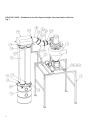
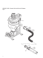
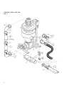
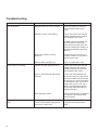
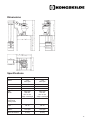
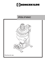
POLYVAC
Directions for use
POLYVAC 30/50 - Standard units with Gaylord height stand and dust collection
Fig. 1
Assembly Instructions Standard units with Gaylord height stand
and dust collection
All instructions refer to Figure 1 on page 2
For proper assembly, follow steps listed below.
a: Mount the Polyvac unit (1) on the stand (2) using
U-bolts (13), flat washers (14) and lock nuts (15).
Make certain that the foundation is secure,
and check regularly that all the mounting
bolts are tight.
b: Attach the filter manifold support arm (3) on the
stand (2).
c: Attach first the OK160/200 transition (10) to blower
outlet with OK160 clamp (12). Then mount 45°
bend (8), OK200 pipe (9), and again a 45° bend (8)
using OK200 clamps. Attach the 4 bags manifold
(4) on the support arm and clamp it to the bend (8).
d: Place drum (7) with lid (6) under the 4-bag manifold
and installs the four filter socks (5). The filter socks
are slid over the OK adapters on drum lid and
manifold and secured with OK200 clamps. Make
sure there is approximately 1 inch of material slid
through the clamp.
List of Equipment
15
8
600366003
5/16" Lock-nut
14
8
100331014
M8 Flat Washer - Plated
13
4
600373028
5/16" x 2-1/2" x 60mm U-bolt
12
1
122000800
OK160 Quick Release Clamp, galv.
11
12
122050101
OK200 Quick Release Clamp, grey
10
1
121000367
OK160/OK200 Transition, grey
9
1
122000455
OKD200 x 0.15m Pipe, grey
8
2
122050115
45" OK200 Bend, galv.
7
1
699114492
45 Gallon Drum w. Window
6
1
699114237
4 x OK200 Inlet Drum Lid.
5
4
699114055
OK200 x 2m Filter Sock
4
1
699114441
4 Bag Manifold w. Side Inlet
3
1
699115792
Polyvac 4 Bag Manifold Bolt-on Stand
2
1
699115160
Polyvac Stand
1d
1
123110003
Polyvac 50, 5hp, 3ph, 575V-60Hz
1c
1
123110002
Polyvac 50, 5hp, 3ph, 460V-60Hz
1b
1
123110001
Polyvac 30, 3hp, 3ph, 575V-60Hz
1a
1
123110000
Polyvac 30, 3hp, 3ph, 460V-60Hz
POLYVAC 30/50 - Standard Units with Suction Flexhose
Fig. 2
Assembly Instructions Standard Units with Suction Flexhose
All instructions refer to Figure 2 on page 4
a: Rotate the Cyclone Inlet (Item A) for the best working position of the Suction Flex hose. Loosen, but
do not remove, the clamps on both top and bottom
of the cyclone. Rotate the cyclone to the desired
position, retighten the clamps.
b: Install the 4" Suction Flex hose. (Item C) First the
OK160 (6") to OK100 (4") adapter (Item B) must be
clamped to the cyclone. The Flex hose is then connected with the OK100 (4") quick clamp.
c: Install the Suction Wand (Item D) to the Flex hose.
Make sure the air intake and handle are located at
the end nearest the hose.
POLYVAC 30/50 - SUC Unit
Fig. 3
Assembly Instructions SUC Unit
For proper assembly, follow steps below. See Figure 3,
Page 6.
3:
Mount the telescopic pipe between the elbows
adjusting the pipe to the desired length. Secure both ends with the pipe clamps.
Slide the rubber O'Ring down the pipe until it rests on the other pipe lip. Place the pipe
clamp around O'Ring and the pipe lip, and
secure clamp.
4:
a: Attach the 4 leg extensions (Item A) to the bottom of the
POLYVAC stand. Requires 16, 1/4 x 3/4" bolts.
b: If the POLYVAC unit is to be mobile, attach the 4 optio- j: Install electrical power to the motor. Follow electrical
nal caster wheels (Item B). Requires
wiring instructions on the inside of motor electrical box.
4, 1/4 x 3/4" bolts.
Note: Make sure the motor is turning in the
c: Mount the Blow Through Unit (Item C) on the bottom of proper direction as shown by the the arrow on the Rotary Valve (Item D). Requires
the fan housing.
4, 5/16 x 2" bolts.
All electrical work must comply with local
d: Mount the POLYVAC unit in a suitable location using the regulations.
bolt plate on the legs of the stand.
Make certain that the foundation is secure, and
check regularly that all mounting bolts are tight.
e: Rotate the Cyclone Inlet (Item E) for the best working
position of the Suction Flex hose. Loosen, but do not
remove, the clamps on both top and bottom of the cyclone. Rotate the cyclone to the desired position, and
retighten the clamps.
f: Attach the Variable Air Intake (Item F) to the Cyclone
with OK160 (6") clamp.
g: Install the 4" Suction Flex hose. (Item H) Clamp the
OK160 (6") to OK100 (4") adapter (Item G) to the variable air intake. Then connect the Flex hose with the
OK100 (4") clamp.
h: Install the Suction Wand (Item I) to the Flex hose. The
air intake and handle are locate at the end nearest the
hose.
i: Install the Intermediate Piping (Item J to L) between the
Fan outlet and the Blow Through Unit.
1:
Attach the 90° Degree (Item J) elbows to the Fan outlet and to the Blow Through using the clamps.
2:
Slide the telescopic pipe with rubber O'Ring (Item K) inside the 12" pipe (Item L).
Note: The seams of the pipe must be aligned for proper function of the telescopic pipe.
Operation of POLYVAC Standard Unit
a: When using the POLYVAC to draw material from
gaylords, bin, etc., a certain amount of air is required in the pipe to keep the material fluidized.
This secondary air is allowed in by adjusting the air
intake (Item G) on the Suction Wand (Item D,
Page 4).
intake (Item M) on the Suction Wand (Item I) and on
the Variable Air Intake (Item F, Page 6).
Initially set both air intakes half way open. No. 5)
Note:
By closing the intake, the conveying capacity is
increased.
By opening the intake, the conveying capacity is
decreased.
By closing the intake, the conveying capacity is
increased.
Note: Do not close off intake too far as material will
stop flowing and lay in the hose. Material must continue to flow.
b: Start up the system. Insure that the end of the Suction Wand does not become plugged with foreign
material or become blocked by the sides or bottom
of the bin.
By opening the intake, the conveying capacity is
decreased.
b: Insure that the end of the Suction Wand does not
become plugged with foreign material or become
blocked by the sides or bottom of the bin.
Note: Large foreign objects entering the wand may
plug and damage the Rotary Valve.
C: Check filter(s) regularly for build up. Clean as required. Restriction of air flow through the filter will
reduce capacity. (Item 5, Page 2)
d: Check the inside of the cyclone periodically for build
up on the screen. Simply remove the clamp holding
the fan housing and the suction cyclone together.
The fan housing is spring loaded and will raise
easily out of the way.
Restriction of air flow through the cyclone screen
will reduce capacity.
Note: Do not operate the POLYVAC with
the fan housing raised. Insure the finger
guard is in place at all times. Exposed fan
rotor may cause serious injury.
Operation of POLYVAC SUC Unit
a: When using the POLYVAC to draw material from
gaylords, bins, etc., a certain amoumt of air is required in the pipe to keep the material fluidized.
This secondary air is allowed in by adjusting the air
Note: Large foreign objects entering the wand may
plug and damage the Rotary Valve.
c: With the Suction Wand in the material, adjust the air
intake on the wand just to the point where material
starts to plug in the flex hose. Now open it up slightly. If more capacity is required adjustments can also
be made on the Variable Air Intake.
d: The variable air intake can be closed slightly, thus
reducing the amount of air entering the system at
this point.
Caution must be used as closing this intake too
much will result in the transfer piping plugging. (ie.
not enough air to carry the product) This plug will
usually occur at a 90° degree elbow heading vertical.
The amount of secondary air required to enter the
system is dependent on the density and size of the
particles being transported, along with the piping
configuration within the system. Some experimentation will be required for each system to optimize the
capacity.
e: Check the inside of the cyclone periodically for build
up on the screen. Simply remove the clamp holding
the fan housing and the suction cyclone together.
The fan housing is spring loaded and will raise
easily out of the way.
Restriction of air flow through the cyclone screen
will reduce capacity.
Note: Do not operate the POLYVAC with
the fan housing raised. Insure the finger
guard is in place at all times. Exposed fan
rotor may cause serious injury.
Maintenance
a: Clean the screen in the cyclone regularly.
Open the clamp between the fan and the cyclone.
Raise the fan housing up. Using an air hose or
small brush remove any foreign material from
the screen. This material will then be discharged
through the rotary valve.
Note: Lock off electrical power before
raising the fan housing. Do not operate the
unit with the fan housing raised.
b: Clean or replace the filter sock(s) regularly.
Tap the filter lightly to remove the dust or material
allowing it to fall to the bottom. When the build up
of material is sufficient, remove the filter and clean
completely.
c: Check paddle adjustment in the Rotary Valve.
Paddles should just contact the wall of the rotary
valve. If there is a gap between them, loosen the
screws and slide the paddle outwards until it contacts the wall. Retighten the screws.
If the paddles are too tight against the wall, the
rotary valve will take too much power to operate, or
may stop turning altogether.
If there is too much gap between the paddles, on
the SUC unit the air pressure used below to convey
the material will blow back into the cyclone. This
will cause reduced conveying capacity and possible
plugging in the transfer lines.
Troubleshooting
Problem
Cause
Remedy
Loss of capacity.
Plugged screen in suction cyclone.
Clean out screen by means of
compressed air and/or steel
brush.
Paddles in rotary valve leaking.
Loosen the screws and slide the
paddle outwards until it contacts
wall. Retighten the screws.
If paddles must be replaced. Follow instructions in the Rotary
Valve manual to remove the cell
wheel and install new paddles. At
this time the bearings should be
checked.
Rotary Valve not working.
Plugging of pressure line - (SUC
Unit).
10
Motors are rotating in wrong
direction.
Change wiring for motor to run
in proper rotation on both the fan
and the rotary valve.
Exhaust filter(s) plugging up.
Clean or replace filter socks.
Paddles too tight against housing.
Loosen the screws and slide the
paddle away from the housing.
Paddles should just contact the
wall. Retighten the screws.
Rotor in valve jammed with foreign
material.
Loosen the clamp between the
fan housing (Item H, Page 2) and
the cyclone (Item A) and raise the
fan housing up. Loosen the clamp
on the bottom of the cyclone and
remove the cyclone. The rotary
valve is now exposed. Remove
any foreign material blocking or
plugging the valve.
Rotor bearings seized.
Remove the end caps and replace
as outlined in the Rotary Valve
service manual.
Not enough air being introduced to
convey material when going into 6"
line from 4" suction line.
Open the Variable Air Intake (Item
F, Page 6) until material flows
freely.
Dimensions
Specifications
Model
30
50
Motor
3 hp
3500 rpm
5 hp
3500 rpm
Frame
182T
184T
Phase33
Voltage
Fan
Rotor
460/575
3500 rpm
360 mm
dia. on one stage centrifugal
3500 rpm
415 mm
dia. on one
stage centrifugal
RF 20
RF 20
Weight w/o 80 lbs
motor and
rotary valve
Rotary valve
type
Rotary valve
Motor
Hose & Nozzles
460/575
0.5 hp
1725 rpm
4" Poly
100 lbs
0.5 hp
1725 rpm
4" Poly
11
123 110 077
18.07.06