1
INSTRUCTION MANUAL
CGW Granulators
Models 1418, 1424, 1436 and 1448
INSTRUCTION MANUAL UGG023-0107
CGW Granulator
INTRO / CONTENT
We reserve the right to change designs, material
and specifications without prior notice.
© Copyright applies to all texts and images in this
instruction manual, in full or in part.
The Conair Group
INSTRUCTION MANUAL UGG023-0107
CGW Granulator
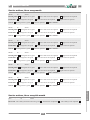
Introduction
DANGER! Read the instruction manual before installing and operating the machine.
This instruction manual contains instructions how to install, operate and maintain the standard versions of the Conair
CGW-series, Model number 1418, 1424, 1436 and 1448, along with additional options suffix (see suffix key below) -K,
-U, -B, -RF. This manual also includes information on the optional wear kit and hardened chamber model and the
economical Solo model.
The performance of your supplied machine may vary from the standard machines described in this instruction manual.
If there are any questions, please contact Conair’s local distributor or Conair’s main office.
1424-KB
1424
1424
1424 Solo
1424-K
Main office:
Suffix Key:
Conair
One Conair Drive
Pittsburgh, PA 15202
USA
K = Sound Enclosure
Phone.
412-312-6000
Facsimile. 412-312-6227
P = Pipe / profile
Website: www.conairgroup.com
INSTRUCTION MANUAL UGG023-0107
U = Blower discharge
B = Band conveyor
RF = Roll feed
CGW Granulator
INTRO / CONTENT
INTRODUCTION
CONTENT
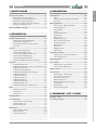
1. SAFETY RULES
2. DESCRIPTION General rules, Safety................................................... 1:1
Warning signs on the machine............................ 1:1
Warnings in the instruction manual.................... 1:1
Safety rules, During Installing............................ 1:2
Safety rules, During start and operation............. 1:2
Safety rules, During service................................ 1:3
Transmission.............................................................. 2:11
Motor................................................................ 2:11
Drive belt, Motor pulley, Rotor pulley............. 2:11
Flywheel........................................................... 2:11
Risk of machinery damage......................................... 1:3
2. DESCRIPTION
Technical specifications.............................................. 2:1
General Data, Supplied machine:....................... 2:1
General Data, CGW-series:................................ 2:1
Personnel responsible for the machine............... 2:1
Overview............................................................. 2:2
Layout.......................................................................... 2:3
CGW 1424 Hopper front ................................... 2:3
CGW 1424-K Hopper front ............................... 2:3
CGW 1424-K Band conveyor front . ................. 2:4
CGW 1424-KU Hopper front .............................. 2:4
CGW 1424 Hopper front Solo............................ 2:5
CGW 1424-B Band conveyor front Solo............ 2:5
Function....................................................................... 2:6
CONAIR CGW series ....................................... 2:6
Additional suffix 1418, 1424, 1436 and 1448.... 2:6
Additional suffix Solo......................................... 2:6
Additional suffix Standard.................................. 2:6
Additional suffix High wear package................. 2:6
Additional suffix -K............................................ 2:7
Additional suffix -U............................................ 2:7
Additional suffix -B............................................ 2:7
Additional suffix -P............................................. 2:7
Additional suffix -RF.......................................... 2:7
Additional suffix -AX......................................... 2:7
Additional suffix -DS, -TRACS, -TP................. 2:7
Rotor............................................................................ 2:8
General rules, Rotor............................................ 2:8
3-blade, rotor....................................................... 2:8
5-blade, rotor....................................................... 2:8
Rotating knives............................................................ 2:8
Cutter housing............................................................. 2:9
General rules, Cutter housing............................. 2:9
Cutter housing 1st............................................... 2:9
Cutter housing 5th............................................... 2:9
Safety equipment....................................................... 2:12
General rules, Safety equipment....................... 2:12
Safety equipment.............................................. 2:13
Inlet, Hopper..................................................... 2:13
Flap(s) .............................................................. 2:13
Screen, Screen box............................................ 2:13
Granule bin....................................................... 2:13
Main switch...................................................... 2:14
Emergency stop(s) ........................................... 2:14
Key to electrical cabinet................................... 2:14
Stand still monitor............................................. 2:14
Safety switch..................................................... 2:15
Star knob........................................................... 2:15
Magnet switch................................................... 2:15
Safety relay....................................................... 2:16
Overload protection.................................................. 2:16
General rules, Overload protection................... 2:16
Overload protection.......................................... 2:16
Operating panel......................................................... 2:16
Level switch............................................................... 2:17
General rules, Level switch ............................. 2:17
Level switch, Paddle type................................. 2:17
Hours counter............................................................ 2:17
Current relay............................................................. 2:18
General rules, Current relay.............................. 2:18
Limit value ( LVA, LV%)................................. 2:18
Hysteresis ( HA, H%)....................................... 2:18
Reaction time (T1)............................................ 2:19
Time delay during start up (T2)........................ 2:19
Yellow LED...................................................... 2:19
Green LED........................................................ 2:19
Function setting (FS)........................................ 2:19
3. TRANSPORT / LIFT / STORE
Transport / Lift............................................................ 3:1
Store the granulator.................................................... 3:1
Fixed knives................................................................. 2:9
Knife grinding fixture....................................... 2:10
Knife clearance ................................................ 2:10
Knife setting fixture.......................................... 2:10
INSTRUCTION MANUAL UGG023-0107
CGW Granulator
INTRO / CONTENT
CONTENT
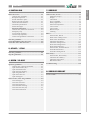
4. INSTALLING
7. SERVICE
Before first start.......................................................... 4:1
General rules, Installing...................................... 4:1
Reception inspection........................................... 4:1
Put the machine in place..................................... 4:1
Remove the rust preventer.................................. 4:1
Check the knife clearance................................... 4:1
Technical specifications . ................................... 4:1
Install the hopper................................................ 4:2
Electrical connection........................................ 4:4
General rules, Electrical connection................... 4:4
Emergency stop ................................................. 4:4
Level switch (optional)....................................... 4:4
Current relay (optional)...................................... 4:4
Connect the granulator to the mains................... 4:4
General rules, Service................................................. 7:1
Emergency stop(s).............................................. 7:1
Flap(s)................................................................. 7:1
Lubrication.......................................................... 7:1
Service schedule................................................. 7:1
Safety equipment................................................ 7:2
Electrical components......................................... 7:2
Level switch........................................................ 7:3
Current relay....................................................... 7:4
Band conveyor.................................................... 7:5
Cleaning . ........................................................... 7:6
Start the granulator.................................................... 4:5
Check immediately after first start........................... 4:5
Check five hours after first start............................... 4:5
5. START / STOP
Start the granulator.................................................... 5:1
Stop the granulator..................................................... 5:1
6. OPEN / CLOSE
Open the granulator................................................... 6:1
General rules, Open the granulator..................... 6:1
Open the enclosure (-K)...................................... 6:1
Open the transmission......................................... 6:1
Open the cutter housing...................................... 6:2
Open the granule bin........................................... 6:3
Open the screen box............................................ 6:3
Open the hopper.................................................. 6:3
Knives........................................................................... 7:7
General rules, Knives.......................................... 7:7
Remove the rotating knives................................ 7:7
Remove the fixed knives.................................... 7:7
Install the fixed knives....................................... 7:8.
Install the rotating knives................................. 7:97.
Preset the rotating knives.................................. 7:10
Preset the fixed knives...................................... 7:10
General rules, Grind the knives........................ 7:11
Grind the fixed knives...................................... 7:11
Grind the rotating knives.................................. 7:12
Drive belt(s)............................................................... 7:13
General rules, Drive belt(s)............................... 7:13
Check the drive belts(s).................................... 7:13
Adjust the belt tension...................................... 7:13
Belt tension table.............................................. 7:14
Troubleshooting......................................................... 7:15
8. SERVICE REPORT
Service actions............................................................. 8:1
General rules, Close the granulator.......................... 6:4
Close the hopper................................................. 6:4
Close the screen box........................................... 6:4
Close the granule bin ......................................... 6:4
Close the cutter housing...................................... 6:5
Close the enclosure (-K)..................................... 6:1
Close the transmission........................................ 6:1
INSTRUCTION MANUAL UGG023-0107
CGW Granulator
INTRO / CONTENT
CONTENT
INTRO / CONTENT
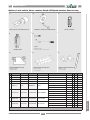
9. SPARE PARTS
General rules, Spare parts......................................... 9:1
Feed tray, Funnel ............................................... 9:2
Inlet .................................................................... 9:3
Flap(s) ................................................................ 9:4
Hopper ............................................................... 9:5
Hopper device .................................................... 9:6
Safety Hopper & Cutter housing ....................... 9:7
Cutter housing .................................................... 9:9
Rotor ................................................................ 9:11
Knives .............................................................. 9:12
Screen box, Screen........................................... 9:14
Granule bin, Discharge .................................... 9:15
Transmission, Motor, Flywheel ..................... 9:16
Safety Transmission ......................................... 9:18
Safety Enclosure .............................................. 9:19
Safety Electrical cabinet .................................. 9:21
Body ................................................................. 9:22
Options, Level switch, Hours counter,
Stand still/Speed monitor, Current relay.......... 9:23
Material transport, Blower,
Band conveyor, Dust separator system ........... 9:24
Blower.............................................................. 9:25
1424-KB
1424 Solo
1424
1424
INSTRUCTION MANUAL UGG023-0107
CGW Granulator
1. SAFETY RULES
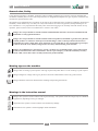
General rules, Safety
The machines are manufactured in accordance to the state of the art and legal safety regulations (guidelines, harmonised
standards), which demand very low safety risk. But, if the machines are incorrectly operated, unexpected dangers can
arise. Therefore it is very important that the safety rules on the following pages are carefully observed. If there are any
questions, please contact Conair’s local distributor or Conair’s main office.
Danger! It is not permissible to feed the machine with flammable material or material contaminated with
flammable or easily ignited substances.
Danger! It is not permissible to feed the machine with wood products, household or garden waste, pharmaceutical products or substances which present a health danger, unless written permission has first been
obtained from Conair’s main office. If any materials are processed that are not contractually agreed upon,
Conair is absolved of any liability and guarantee for safety and functioning of the machine.
Danger! No modifications or alterations to Conair’s products are permissible unless written approval has
first been obtained from Conair’s Main Office. This is to prevent injury, so that the machinery warranty
will be valid, and so that Conair can fully assume their product liability.
Warning signs on the machine
Danger! Risk of cutting or pinch injuries! This sign is placed anywhere there is a risk of cutting or pinch injuries.
Danger! Dangerous voltage! This sign is placed on electrical cabinet hatches and on any junction boxes.
Danger! Read the instruction manual before installing and operating the machine.
Warnings in the instruction manual
Danger! This symbol is used to indicate risk of personal injury. The symbol inside the triangle may have different
appearances, depending on the type of danger.
Important! This symbol is used to indicate risk of machinery damage.
Information! This symbol is used to highlight useful information.
INSTRUCTION MANUAL UGG023-0107
1:1
CGW Granulator
SAFETY RULES
Conair designs granulators, shredders, guillotines and surrounding equipment for processing injection moulded, blow
moulded or extruded plastics waste. Size and performance is designed and adapted to the type of plastic residue that the
customer has specified before order.
1. Safety rules
Safety rules, During Installing
• The machine must be installed by authorized, trained personnel.
• All instructions must be observed to avoid machinery damage and personal injury.
• The machine must be installed and connected to other equipment so that the entire installation complies with the
stipulations of the Machinery Directive 98/37/EG.
Safety rules, During start and operation
• The instructions in the instruction manual must be followed.
• National environmental and employee safety regulations must be followed.
• The machine must be correctly installed.
• The hatches for electrical cabinets, transmission and pneumatics (if installed) must be closed during start and operation. The key must be kept by the personnel responsible for the machine’s service and safety.
• The screen must be installed.
• The screen box must be closed.
• The granule bin must be closed.
• The hopper must be closed.
• All safety switches must be installed.
• All outer safety equipment such as protective screens, bars, covers, plates, nets etc must be installed.
• Body with wheels (optional): The wheels must be locked.
• Be very careful. The machine contains rotating knives. Risk of cutting or pinch injuries!
• Never place any part of your body in any opening. Risk of cutting or pinch injuries!
• Use ear defenders. Risk of loud, damaging noise!
• Use protective goggles. Risk of granulate splashing!
• Do not tread on the machine.
• Granulator with additional suffixes -K (Enclosure):
- The enclosure must be closed.
• Granulator with additional suffixes -U (Blower):
- Be very careful. The blower has very powerful suction and blowing ability. Never place any parts of your body in or
near the suction or blower outlet openings.
- Blowers must not be used in ambient temperatures above +40°C, in ambient temperatures below -20°C, in explosion
hazard atmospheres or unprotected outdoors.
- The temperature of the transported material must never increase +80° C.
• Granulator with additional suffixes -B (Band conveyor):
- Be very careful. Clothing and parts of your body can be dragged along with the conveyor band.
- Do not tread on the band conveyor.
- If hot material is to be transported on the band, this must be placed in the middle of the band. Uneven heating of the
band can make the band pull to one side.
INSTRUCTION MANUAL UGG023-0107
1:2
CGW Granulator
SAFETY RULES
1. Safety rules
• The instructions in the instruction manual must be followed.
• National environmental and employee safety regulations must be followed.
• First aid and eye shower must be within reach.
• Daily service and daily checks may be done by the operator. All other service and inspections must be done by authorised, trained personnel.
• Always work alone at the machine when service actions is performed.
• Use protective goggles and gloves.
• The granulator’s main switch must be locked in position “0”. Never insert any part of your body into any opening,
unless the main switch is locked in position “0”.
• The granulator must be disconnected from the mains before electrical repairs is began.
• Be very careful – When opening and closing the machine. Risk of cutting or pinch injuries!
• Be very careful – When checking and changing drive belt. Risk of cutting or pinch injuries!
• Be very careful – When the machine is opened the knives are accessible. The knives are sharp, and they may cause
personal injuries even when they are not rotating. Risk of cutting or pinch injuries!
• Be very careful – When the rotor is to be turned manually. The rotor can rotate by itself. Always lock the rotor with a
piece of wood to avoid the rotor from self-rotating.
• Be very careful – When cleaning granulate and plastic residue can make the floor slippery.
• Be very careful – When working on high level. Only use specially installed and fastened steps, stairs and platforms. It
is not permissible to remove any outer safety equipment such as protective screens, bars, nets etc.
• After service / check is done the hatch(es) for the electrical cabinet, transmission and pneumatics (if installed) must be
closed and locked. The key must be kept by the personnel responsible for the machine’s service and safety.
• Granulator with additional suffixes -B (Band conveyor):
- The band conveyor’s main switch must be locked in position “0”.
- The band conveyor’s mains plug must be disconnected from the mains.
Risk of machinery damage
• If incorrect material is fed into the machine.
• If the belt tension is incorrect or if the drive belts are worn.
• If the screen in the screen box is worn or incorrectly installed.
• If the knives’ tightening screws are tightened with incorrect torque.
• If the knives are blunt.
INSTRUCTION MANUAL UGG023-0107
1:3
CGW Granulator
SAFETY RULES
Safety rules, During service
2. DESCRIPTION
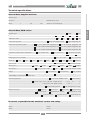
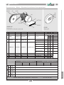
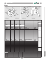
Technical specifications
General Data, Supplied machine:
Serial No:............................................................................. Manufacturing year:...........................................................
Motor: .................. V
Electrical circuit diagram: ................................................
.................. Hz .................. kW
General Data, CGW-series:
Machine type: .............................................................................................................................
Model: ..........................................................................................................
1418
Additional suffix: ...............................................................................................
Cutter housing (CH): ................................................................
CGW
1424
-K
Solo
1436
-U
-B
Restricted Tangential, 1st
1448
-P
- RF
Super Tangential, 5th
Cutter housing width (Inside): ..................
17 x 18 in (Restricted Tangential, 1st)
14 x 18 in (Super Tangential, 5th)
...................................................................
17 x 24 in (Restricted Tangential, 1st)
14 x 24 in (Super Tangential, 5th)
....................................................................
17 x 36 in (Restricted Tangential, 1st)
14 x 36 in (Super Tangential, 5th)
Fixed knives (Reversible, Grind able): ........
2 pcs (2nd & 5th)
2 pcs (2nd & 1st)
3 pcs (2nd, 1st & 5th)
Rotor: ...........................................................................................................................................
Rotating knives (Grind able): .......................................................................
Screen Ø: .
4 mm
5 mm
6 mm
8 mm
10mm
Motor power: ...................................... 7.5 kW
Drive belt(s): .............................................
11 kW
3 pcs
1418 (2094 lb)
Sound level*, Idle running:
Std. Unit No Soundproofing, 90-95 dbA
*(Depending on capacity, temperature etc)
Optional equipment: .......................................................................
............................................................
17 mm
30 kW
5-blade
5 pcs / 1x5 (5-bl)
25 mm
1500 rpm (50 Hz)
18.5 kW
3 pcs (7.5 kW, 11 kW)
Weight: ....................................................................................
3 pcs / 1x3 (3-bl)
12 mm
Rotor speed: .................................................................................................
3-blade
Hardened
1800 rpm (60 Hz)
37 KW
Flywheel
4 pcs (18.8 kW, 30 kW, 37 kW)
1424 (2425 lb)
1436 (3600 lb)
With Optional Soundproofing, 80-85 dbA
Level switch, Paddle switch
Hours counter
Current relay LVA, Y/D-start: Rated current .......... (/1A ) / √3 = ........... A
.......................................................................................... LVA, Direct-start: Rated current .......... (/1A) / 1 = ........... A
................................................................................................
Material transport:...............................................
.....................................................................
Blower F7
Band conveyor
....................................................................................
Knife grinding fixture
Blower F15
Knife setting fixture, Long
Blower F25
Metal detector, Tunnel
Cyclone AX 7.5
Cyclone AX 12
Blower F25-K
Metal detector, Area
Cyclone AX 16
Personnel responsible for the machine’s service and safety:
Name:.................................................................................. Phone: ..............................................................................
Name:.................................................................................. Phone: ..............................................................................
INSTRUCTION MANUAL UGG023-0107
2:1
CGW Granulators
DESCRIPTION
Machine type: ........................................................................................................................................................................
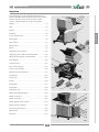
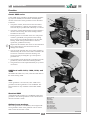
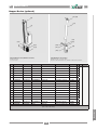
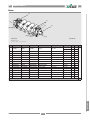
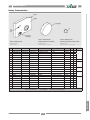
2. DESCRIPTION Overview
The performance of your supplied machine may vary
from the standard machines described in this instruction
manual. If there are any questions, please contact
Conair’s local distributor or Conair’s main office.
(1)
(2) (3)
(4)
Hopper ......................................................................... (1)
Inlet .............................................................................. (2)
(5)
Flap(s) .......................................................................... (3)
DESCRIPTION
Feed tray ...................................................................... (4)
Cover, Transmission .................................................... (5)
Rotor pulley ................................................................. (6)
Drive belt(s).................................................................. (7)
Motor pulley ................................................................ (8)
(6)
(7)
(8)
(9)
(10)
Motor ........................................................................... (9)
Tightening screws, Motor .......................................... (10)
(11)
Adjusting screws, Motor mounting bracket . ............. (11)
Safety Switch, Hopper / Cutter housing .................... (12)
Jack, Hopper .............................................................. (13)
Cutter housing . .......................................................... (14)
Door, Cutter housing . ................................................ (15)
Catch, Cutter housing ................................................ (16)
(14)
(12)
(15)
(16)
(13)
Magnet switch, Granule bin........................................ (17)
Granule bin ................................................................ (18)
Screen box ................................................................. (19)
(17)
Screen ........................................................................ (20)
Start-button................................................................. (21)
Stop-button ................................................................ (22)
(18)
(19)
Emergency stop . ........................................................ (23)
(20)
1424
Button “Reset Safety Relay” . .................................... (24)
(12)
Button “Operate 1” .................................................... (25)
(21)
(24)
Button “Operate 2” .................................................... (26)
(25)
Knob “Hopper, Close / Open” ................................... (27)
Hatch, Electrical cabinet............................................. (28)
Lock, Electrical cabinet.............................................. (29)
(26)
(27)
Main switch ............................................................... (30)
Enclosure ................................................................... (31)
(28)
(29)
(22)
(23)
(30)
(31)
1424-K
INSTRUCTION MANUAL UGG023-0107
2:2
CGW Granulators
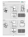
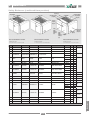
2. DESCRIPTION
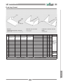
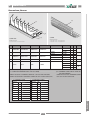
Layout
CGW 1424
Hopper front
DESCRIPTION
LAYOUT NO: 4-53000-C01
CGW
1418
1424
1436
A
450
600
900
B
1290
1440
1740
C
1620
1770
2070
D
1800
1950
2250
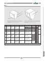
CGW 1424-K
Hopper front
LAYOUT NO: 4-53000-C01
INSTRUCTION MANUAL UGG023-0107
2:3
CGW
1418
1424
A
450
600
1436
900
B
1340
1490
1790
C
1620
1770
2070
D
1950
2100
2400
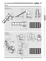
CGW Granulators
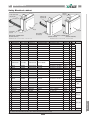
2. DESCRIPTION
Layout
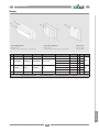
CGW 1424-KB
Band conveyor front
DESCRIPTION
LAYOUT NO: 4-53015-C01
CGW
1418
1424
1436
A
450
600
900
B
1340
1490
1790
C
1620
1770
2070
D
1950
2100
2400
CGW
1418
1424
1436
A
450
600
900
B
1340
1490
1790
C
1620
1770
2070
D
1950
2100
2400
CGW 1424-KU
Hopper front
BLOWER F25 AX16-K
LAYOUT NO: 4-53014-C01
INSTRUCTION MANUAL UGG023-0107
2:4
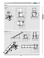
CGW Granulators
2. DESCRIPTION
Layout
CGW 1424
Hopper front
Solo
DESCRIPTION
LAYOUT NO: 4-53024-B01
CGW 1424-B
Band conveyor front
Solo
LAYOUT NO: 4-53025-B01
INSTRUCTION MANUAL UGG023-0107
2:5
CGW Granulators
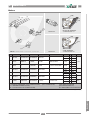
2. DESCRIPTION Function
Conair CGW-series
(C)
(A)
1. The plastic residue, which must be free from metal
and contamination, is fed into the granulator’s inlet.
The inlet may be provided with a feed tray or a funnel.
2. The plastic residue falls through the hopper and down
into the cutter housing. The cutter housing contains
fixed knives and a rotor.
3. Rotating knives are mounted on the rotor. The plastic
residue is granulated (cut up) between the rotating
knives on the rotor and the fixed knives in the cutter
housing. Both rotating and fixed knives must be
replaced or grinded as necessary.
Important! The machine must never be used with blunt
knives. Blunt knives cause abnormal wear and
damages the machine.
4. The size of the granulate (the cut up plastic residue) is
determined by the screen. The screen is installed in the
screen box in the base of the cutter housing. The
screen can easily be changed to give the required
granulate size.
5. The granulate passes through the screen down into the
granule bin, which collects the finished granulate.
6. The granule bin can be emptied manually or by means
of a blower.
(B)
(D)
(E) (F)
(G)
(I)
(J)
(H)
Additional suffix 1418, 1424, 1436, and
1448
The additional suffix 1418, 1424, 1436 and 1448 refers to
the cutter housing width.
Solo
A Solo granulator is an economic, basic CGW-series
granulator. The Solo granulator is not modifiable. The
Solo granulator is only available in the model number
1424.
(G)
Standard CGW
A Standard CGW granulator is a modifiable CGW-series
granulator. Parts of the granulator can be custom built to
meet the customre’s needs.
Optional wear package
The CGW granulator is a modifiable, extra tough CGWseries granulator. Parts of the granulator can be custom
built to meet the customer’s needs.
(F)
(E)
(A)= Feed tray
(B)= Inlet
(C)= Flap(s)
(D)= Hopper
(E)= Screen
(F)= Screen box
(G)= Granule bin
(H)= Fixed knife
( I ) = Rotating knife
(J)= Cutter housing
Continued
INSTRUCTION MANUAL UGG023-0107
2:6
CGW Granulators
DESCRIPTION
Conair CGW-series granulators are designed for granulating injection molded, blow molded or extruded plastic
residue. The function of the granulator can be described
as follows:
2. DESCRIPTION Function (continued from previous)
Additional suffix -K
(A)
Granulator with additional suffix -K is provided with a
sound insulating enclosure. >Page 9:19 “Enclosure”
Additional suffix -U
(C)
Additional suffix -B
Granulator with additional suffix -B is provided with a
band conveyor. The band conveyor transports plastic
residue to the granulator’s inlet / hopper. The band
conveyor can be provided with a metal detector. >Page
9:24 “Material transport”.
(D)
Additional suffix -P
Granulator with additional suffix -P is provided with a
hopper that is adapted to granulation of pipes and profiles.
>Page 9:5 “Hopper”.
(E)
Additional suffix -RF
Granulator with additional suffix -RF is provided with a
roll feed. The roll feed contains rotating rollers which
feed the plastic residue into the granulator’s cutter
housing. Optional roll feed RFL, RFS, RFM. >Please
refer to the separate instruction manual “CGW RF”.
(F)
Additional suffix -AX
Granulator with additional suffix -AX is provided with a
cyclone. The cyclone separates air from the finished
granulate. The cyclone’s air outlet can be provided with a
filter. Optional cyclones; AX7.5, AX12, AX16.
Additional suffix -DS, -TRACS, -TP
Granulator with additional suffix -DS is connected with a
dust separator system. The dust separator system cleans
the finished granulate. Optional dust separator systems;
DS400, TRACS, TP2119 or TP2111. >Page 9:24 “Material transport”.
INSTRUCTION MANUAL UGG023-0107
2:7
(A)= Enclosure (-K)
(B)= Blower (-U)
(C)= Band conveyor (-B)
(D)= Roll feed (-RF)
(E)= Cyclone (-AX)
(F)= Dust separator system (-DS)
CGW Granulators
DESCRIPTION
(B)
Granulator with additional suffix -U is provided with a
blower. The blower transports granulate on from the
granule bin to units such as a dust separation system or a
granulator container for later use. Blowers are available
with or without sound insulating enclosure. Optional
blowers; F7, F15 or F25. >Page 9:25 “Blower”.
2. DESCRIPTION
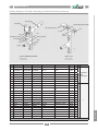
Rotor
General rules, Rotor
(A)
The rotor is designed and adapted to the type of plastic
residue that the customer has specified before order.
CGW-series can be provided with a 3-blade rotor or a 5blade rotor. >Page 9:11 “Rotor”.
3-blade rotor
DESCRIPTION
The 3-blade rotor has three knife rows with one rotating
knife per row.
5-blade, rotor
The 5-blade rotor has five knife rows with one rotating
knife per row.
Rotating knives
Rotating knives are mounted on the rotor. The rotating
knives are fixed with washers and tightening screws. The
rotating knife is provided with adjusting screws that
facilitates the knife clearance setting.
>Page 7:9 “Install rotating knives”.
(B)
The granulator must never be used with blunt knives.
Blunt knives cause abnormal wear and damages the
granulator. The rotating knives must be replaced or
grinded as necessary.
>Page 7:12 “Grind the rotating knives”.
>Page 9:12 “Knives”.
(D)
(C)
(E)
(F)
(A)= 3-blade rotor
(B)= 5-blade rotor
(C) = Rotating knife
(D)= Adjusting screw, Rotating knife
(E)= Tightening screw, Rotating knife
(F)= Washer, Rotating knife
INSTRUCTION MANUAL UGG023-0107
2:8
CGW Granulators
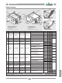
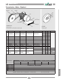
2. DESCRIPTION
Cutter housing
(A)
(G)
(F)
(2nd)
The cutter housing is designed and adapted to the type of
plastic residue that the customer has specified before
order. The cutter housing can be provided with two or
three fixed knives, depending on type of cutter housing.
There are two types of cutter housings, cutter housing
Restricted Tangential; “First” and cutter housing Super
Tangential; “Fifth”.
>Page 9:9 “Cutter housing”
DESCRIPTION
General rules, Cutter housing
(G)
(F)
(1st)
Cutter housing Restricted Tangential;
“First”
Cutter housing Restricted Tangential; “First” has a
tangential back. Cutter housing Restricted Tangential;
“First” has three knife seats.
(5th)
(F)
(G)
Possible configurations:
• Front fixed knife (2nd), Rear fixed knife (5th),
Rear fixed knife (1st).
(B)
(G)
(F)
(2nd)
• Front fixed knife (2nd), Rear fixed knife (5th).
(The empty knife seat must be provided with a
dummy).
Cutter housing Super Tangential; Fifth
Cutter housing Super Tangential; Fifth has a super
tangential back. Cutter housing Super Tangential; Fifth
has two knife seats.
Possible configurations:
• Front fixed knife (2nd), Rear fixed knife (5th).
(5th)
(F)
(G)
Fixed knives
(C)
The front fixed knife is installed in the cutter housing’s
front. The rear fixed knife/knives is/are installed in the
cutter housing’s back. The fixed knives are fixed with
support rules and tightening screws. The fixed knife is
provided with adjusting screws that facilitates the knife
clearance setting. >Page 2:10 “Knife clearance”
The granulator must never be used with blunt knives.
Blunt knives cause abnormal wear and damages the
granulator. The fixed knives must be replaced, grinded or
reversed as necessary. Fixed knives are reversible, this
means that the fixed knives have two cutting edges and
can be reversed once before grinding or discarding is
necessary.
INSTRUCTION MANUAL UGG023-0107
2:9
(D)
(H)
( I)
(E)
(A)= Cutter housing 1st
(B)= Cutter housing 5th
(C)= Fixed knife
(D)= Tightening screw, Fixed knife
(E)= Adjusting screw, Fixed knife
(F)= Support rule, Fixed knife
(G)= Grub screw, Cutter housing
(H)= Cutting edge No 1, Reversible fixed knife
( I )= Cutting edge No 2, reversible fixed knife
(1st) = Rear fixed knife, 1st “First”
(2nd) = Front fixed knife, 2nd (Second)
(5th) = Rear fixed knife, 5th “Fifth”
CGW Granulators
2. DESCRIPTION
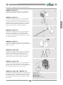
Knifegrindingfixture
The knife grinding fixture (optimal) is used when
grinding the knives. The knife grinding fixture has two
knife positions, one adapted for the fixed knife and one
adapted for the rotating knife.
>Page 7:11 “General rules, Grind the knives”.
>Page 9:23 “Options / Knife grinding fixture”.
DESCRIPTION
(A)
Knifeclearance
The knife clearance is the gap between the fixed knife
and the rotating knife. Correct knife clearance is
0.008–0.016 in {0.20– 0.40 mm}. The knife clearance is
checked with a feeler gauge. >Page 7:8 point 13 “Install
the fixed knives”.
The knife clearance is adjusted by tightening / unscrewing the knife’s adjusting screws. The knife clearance is
adjusted in a knife setting fixture.
>Page 2:10 “Knife setting fixture”.
(B)
Knifesettingfixture
The knife setting fixture is used when presetting the
knives’ adjusting screws.
>Page 7:10 “General rules, Preset rotating the rotating
knife” and “Preset the fixed knife”.
>Page 9:23 “Options / Knife setting fixture”.
Two short knife setting fixtures are enclosed on delivery.
One is meant for presetting rotating knives and the other
is meant for presetting fixed knives.
(C)
0.2
There is also a long knife setting fixture available
(optional). The long knife setting fixture is convenient as
it makes it possible to preset the knife in one step.
(D)
(e)
(A) = Knife grinding fixture
(B) = Knife clearance
(C) = Adjusting screw, Knife clearance
(D) = Knife setting fixture
(e) = feeler gauge
INSTRUCTION MANUAL UGG023-0107
2:10
CGW Granulators
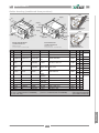
2. DESCRIPTION
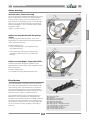
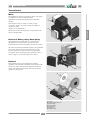
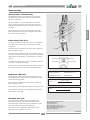
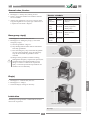
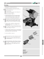
Transmission
Motor
(G)
DESCRIPTION
The granulator is driven by an electric motor. The motor
is installed on a motor mounting bracket.
Optional motor speed: 1500 rpm (50 Hz) or 1800 rpm
(60 Hz).
Optional motor power: 10 Hp {7.5 kW}, 15 Hp
{11.0 kW}, 25 Hp {18.7 kW}, 40 Hp {29.8 kW}, or
50 Hp {37.3 kW}.
>Page 9:16 “Transmission”.
Motor power and motor frequency are specified on the
motor’s machine plate.
Drive belt, Motor pulley, Rotor pulley
(A)
The granulator is provided with 3 or 4 drive belts
depending on the motor power. The drive belts are
tensioned between the motor pulley and the rotor pulley.
The drive belts must be checked regularly. The granulator
must not be driven with worn drive belt(s) nor with
incorrect belt tension. The belt tension is adjusted by
moving the motor mounting bracket upwards or downwards. >Page 7:13 “General rules, Drive belt(s)”.
(C)
Flywheel
The granulator may be provided with a flywheel
(optional). The flywheel is installed on the opposite side
of the rotor pulley. The flywheel optimizes the kinetic
energy and makes the granulator even more powerful.
>Page 9:16 “Flywheel”.
(E)
(D)
(F)
(A)
(B)
(E)
(C)
(D)
(A)= Motor
(B)= Motor mounting bracket
(C)= Drive belt(s)
(D)= Motor pulley
(E)= Rotor pulley
(F)= Flywheel
(G)= Machine plate
INSTRUCTION MANUAL UGG023-0107
2:11
CGW Granulators
2. DESCRIPTION
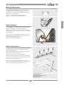
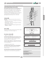
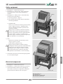
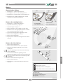
Safety equipment
General rules, Safety equipment
Inside the machine, knives rotate at high speed. For this
reason, there is safety equipment which is intended to
prevent access to hazardous components during operation.
DESCRIPTION
The safety equipment must not be changed or modified
under any circumstances. If any part of the safety
equipment is changed or left out, the machine can be
dangerous to use. If any part of the safety equipment is
changed or left out, Conair’s responsibility under the
Machinery Directive ceases to apply.
The safety equipment must be checked regularly. No part
of the safety equipment may be replaced by components
other than spare parts supplied by Conair.
The safety equipment consists of:
• Inlet
• Hopper
• Flap(s)
• Screen
• Screen box
• Granule bin
• Main switch
• Emergency stop
• Stand still monitor
• Safety switch
• Star knob (Solo)
• Magnet switch
• Safety relay
Note! All these parts must be installed during start and
operation.
• In addition, the key for the electrical cabinet, transmission and pneumatic cabinets (if installed), is part of the
safety equipment.
Continued
INSTRUCTION MANUAL UGG023-0107
2:12
CGW Granulators
2. DESCRIPTION
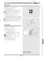
Safety equipment (continued from previous)
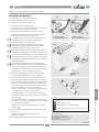
Inlet, Hopper
(C)
(A)
The hopper is designed and adapted to the type of plastic
residue that the customer has specified before order.
>Page 9:5 “Hopper”.
(B)
The inlet is designed and adapted to the type of plastic
residue that the customer has specified before order.
>Page 9:3 “Inlet”.
(D)
The inlet may be provided with a feed tray or a funnel.
>Page 9:2 “Feed tray, Funnel”.
Flap(s)
(E) (F)
The flap(s) prevents fed material from rejecting. The
flap(s) also prevents half-finished granulate from stenching out of the inlet. The flap(s) must be installed during
start and operation. The flap(s) must be regularly checked
and replaced as necessary. >Page 9:4 “Flap(s)”.
(G)
Screen, Screen box
The screen prevents access to hazardous components
during operation. The screen must be installed during
start and operation. The screen box must be closed during
start and operation.
The screen is installed in the screen box in the base of the
cutter housing. The screen can easily be changed to give
the required granulate size.
The screen and the screen box are designed and adapted
to the type of plastic residue that the customer has
specified before order. >Page 9:14 “Screen, Screen box”.
Granule bin
The granule bin collects the finished granulate. The
granule bin must be closed during start and operation.
The granule bin is designed and adapted to the type of
plastic residue that the customer has specified before
order. >Page 9:15 “Granule bin”.
(G)
(F)
(E)
The granule bin may be provided with a level switch
(optional). >Page 2:16 “Level switch”.
The granule bin may be provided with a blower
(optional). >Page 2:7 “Additional suffix -B”.
(A)= Feed tray
(B)= Inlet
(C)= Flap(s)
(D)= Hopper
(E)= Screen
(F)= Screen box
(G)= Granule bin
Continued
INSTRUCTION MANUAL UGG023-0107
2:13
CGW Granulators
DESCRIPTION
The inlet and the hopper prevent access to hazardous
components during operation. The inlet must be installed
during start and operation. The hopper must be closed
during start and operation.
2. DESCRIPTION
Safety equipment (continued from previous)
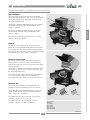
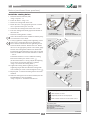
Main switch
The main switch cuts all 3 phases of the supply voltage.
The design and location of the main switch can vary. The
granulator’s main switch must be locked in position ”0”
during service.
(A)
(B)
(C)
Emergency stop(s)
DESCRIPTION
The emergency stop stops the machine in case of emergency. The machine may be provided with several
emergency stops. The emergency stop(s) must be checked
regularly.
The design and location of the emergency stop(s) can
vary. The electrical circuit diagram shows the number of
emergency stop(s) installed in the supplied machine.
Key to electrical cabinets, transmission
and pneumatic
(D)
Hatches to electrical cabinet, transmission and pneumatics (if installed) must be closed and locked during start
and operation. The key must be kept by the personnel
responsible for the machine’s service and safety.
Stand still monitor
The stand still monitor monitors if the rotor is rotating or
if it stands still.
The stand still monitor affects the lamp in the button
“Operate 1” (optional). The button “Operate 1” is lit as
the rotor stands still. The button “Operate 1” is used when
opening a heavy hopper” >Page 6:3 “Open the hopper”.
The stand still monitor affects the switch key in the safety
switch. >Page 2:15 “Safety switch”.
As long as the rotor is rotating the switch key will be
locked inside the safety switch. (This means that it is not
possible to open the machine immediately after stopping
the machine, as the rotor will keep rotating for some
minutes before it slows down and stands completely still.)
As the rotor stands still the switch key is released and the
green LED on the safety switch is lit.
(A)= Emergency stop
(B)= Main switch
(C)= Lock, Electrical cabinet
(D)= Key to electrical cabinet, transmission and pneumatics
Continued
INSTRUCTION MANUAL UGG023-0107
2:14
CGW Granulators
2. DESCRIPTION
Safety equipment (continued from previous)
Safety switch
The machine may be provided with several safety
switches which stops the machine if an unsafe mode is
detected. The safety switch(es) must be checked regularly.
(D)
Standard CGW models: To be able to release the switch
key from the safety switch, the green LED on the safety
switch must be lit. >Page 2:14 “Stand still monitor”.
Standard CGW model
The design and location of safety switches can vary.
Examples of where safety switches might be located can
be seen in the figure on the right. The electrical circuit
diagram shows the number of safety switches installed in
the supplied machine.
Star knob
The machine may be provided with several star knobs
which locks the machine. The star knob has a screw with
a very long thread. The thread is so long because it has to
take such a long time to unscrew the star knob that the
rotor will have time to stop completely.
CGW Solo models
The star knob(s) must be checked regularly. Star knob
with worn screw must only be replaced with a Conair
original screw.
Some star knobs may be provided with a safety switch. If
such a star knob is unscrewed during operation its safety
switch will stop the machine. To be able to start the
machine, the star knob(s) must be screwed in until they
stop moving.
The design and location of star knobs can vary. Examples
of where star knobs might be located can be seen in the
figure on the right.
(A)(B)(C)
(E)(F)
Standard CGW model
CGW Solo models
Magnet switch
The machine may be provided with several magnet
switches that stops the machine if an unsafe mode is
detected. To be able to start the machine, the two magnet
halves must mate up close to each other.
Examples of where magnet switches might be located can
be seen in the figure on the right. The electrical circuit
diagram shows the number of magnet switches installed
in the supplied machine.
(G)
All models
(G)
(A)= Star knob, Solo
(B)= Safety switch, Solo
(C)= Switch key, Solo
(D)= Diode light, Safety switch
(E)= Safety Switch, Standard CGW
(F)= Switch key, Standard CGW
(G)= Magnet switch
Continued
INSTRUCTION MANUAL UGG023-0107
2:15
CGW Granulators
DESCRIPTION
To be able to start the machine, the switch key must be
installed inside the safety switch.
2. DESCRIPTION
Safetyequipment(continuedfromprevious)
Safetyrelay
Standard CGW models are provided with a button “Reset
safety relay”. The button “Reset safety relay” is installed
on the operating panel. To be able to start the machine the
button “Reset safety relay” must be pressed and lit. >Page
5:1 “Start the granulator” point 5.
(A)
Reset
safety relay
If the button “Reset safety relay” does not light up, the
safety relay has to be checked. >Page 7:3.
DESCRIPTION
(B)
(C)
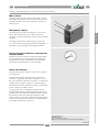
Overloadprotection
Generalrules,Overloadprotection
The machine may be provided with several overload
protections. The electrical circuit diagram shows the
number of overload protections installed in the supplied
machine. The overload protection(s) is/are installed inside
the electrical cabinet.
The overload protection trips if the granulator or any
optional equipment is overloaded. Before resetting an
overload protection and before restarting the machine, the
reason why the overload protection tripped must be
determined. Take necessary actions (for example clean
the machine) to prevent the overload protection from
immediate trip when restarting the machine.
Overloadprotection
If the reset knob is in position ”0” the overload protection
has tripped. The overload protection is reset by turning
the reset knob to position ”1”.
Solo
Standard CGW
(D)
Operatingpanel
(e)
The machine may be provided with several operating
panels. The design and location of the operating panel can
vary. The operating panel(s) can be integrated with the
electrical cabinet’s hatch and / or detached.
(A) = Button, “Reset safety relay”
(B) = Overload protection
(C) = Reset knob
(D) = Operating panel, Integrated
(e) = Operating panel, Detached
INSTRUCTION MANUAL UGG023-0107
2:16
CGW Granulators
2. DESCRIPTION
Level switch
General rules, Level switch
(A)
The granule bin may be provided with a level switch
(optional). The level switch monitors the granule bin’s
granulate level.
As the granulate level gets too high, the level switch takes
one or several of the below listed actions:
DESCRIPTION
• Stops the optional feed equipment (such as a band
conveyor or a roll feed).
• Lights up an optional warning lamp.
• Starts up an optional siren.
• Resets the level switch and restarts the granulator and/
or the feed equipment as the granulate level in the
granule bin has sunk.
Level switch, Paddle type
The paddle switch is provided with rotating paddles.
When the granulator is started the paddles starts rotating.
If the granulate level gets too high, the paddles will stop
rotating. As the paddles stands still, the level switch is
activated.
The paddle switch’s sensitivity can be adjusted by
changing the position of the torsion spring. On delivery
the paddle switch’s torsion spring is installed in the
second hole from the left. >Page 7:4 point 4 “Level
switch”.
(B)
(C)
Hours counter
The granulator may be provided with an hours counter
(optional). The hours counter counts the time the rotor is
rotating. The hours counter has no reset.
(D)
(A)= Level switch, Paddle type
(B)= Siren, Level switch
(C)= Warning lamp, Level switch
(D)= Hours counter
INSTRUCTION MANUAL UGG023-0107
2:17
CGW Granulators
2. DESCRIPTION
Current relay
General rules, Current relay
The granulator may be provided with a current relay
(optional). The current relay monitors the granulator’s
current consumption.
(A)
As the granulator’s current consumption exceeds the
upper current level (LVA), the current relay trips and
stops the feed equipment (such as a band conveyor or a
roll feed).
(B)
(C)
The current relay is preset to automatically restart the
feed equipment as the current consumption has sunk to
the lower current limit (HA).
DESCRIPTION
(D)
(E)
(F)
Limit value ( LVA, LV%)
The limit value (LVA) is the preset current consumption
level where the current relay trips and stops the feed
equipment.
The limit value is adjustable. The limit value’s adjusting
knob is graded 0–100%.
(G)
The limit value in Ampere (LVA) is calculated as shown
in the LVA-formulas on the right. Note! LVA is calculated
differently as the granulator is “Y/D-started” or “Directstarted”.
(G)
Memory On
The limit value percentage (LV%) is calculated as shown
in the LV% -formula on the right.
Memory Of
Undercurrent
Excess current
The electrical circuit diagram shows the rated current and
the current transformer’s size in the supplied machine.
Hysteresis ( HA, H%)
The hysteresis is the preset current consumption level
which determines when the current relay shall reset and
restart the feed equipment.
The hysteresis is adjustable. The hysteresis’ adjusting
knob is graded 5–50%.
LVA (Y/D-start)
=
Rated current / √3
LVA (Direct-start)
=
Rated current
LV%
=
The hysteresis percentage (H%) applies to the limit value.
The hysteresis in Ampere is calculated as shown in the
HA-formula on the right.
HA
=
( LVA x 100 )
Current transformer size
LVA – ( LVA x H% )
100
Reaction time (T1)
The reaction time is the preset period of time that
determines how long the current consumption shall
exceed the upper current level (LVA) before the current
relay shall trip and stop the feed equipment.
The reaction time is adjustable. The reaction time’s
adjusting knob is graded 0.1–3.0 sec.
(A)= Limit value percentage, LV%
(B)= Reaction time, T1
(C)= Time delay, T2
(D)= Hysteresis percentage, H%
(E)= Yellow LED, Current consumption
(F)= Green LED, Control voltage
(G)= Function settings
Continued
INSTRUCTION MANUAL UGG023-0107
2:18
CGW Granulators
2. DESCRIPTION
Current relay (continued from previous)
Time delay during start up (T2)
The time delay during start up is the preset period of time
that determines how long the current consumption is
allowed to exceed the upper current level during start.
(When starting a machine the current consumption may
temporarily exceed the upper current level (LVA).)
(A)
(B)
The function “Time delay during start up” is not used on
Conair granulators. The time delay during start up’s
adjusting knob should always be set to 0 seconds.
(C)
DESCRIPTION
(D)
(E)
Yellow LED
(F)
The yellow led indicates the status of the current consumption.
• Steady light = The current consumption lies below the
upper current level (LVA).
• Flashing light = The current consumption exceeds the
upper current level (LVA).
• Light is out = The current relay has tripped, the feed
equipment is stopped.
(G)
(G)
Green LED
Memory On
The green LED indicates the status of the control voltage.
• Steady light = The control voltage is on.
Memory Of
Undercurrent
Excess current
Function setting (FS)
• Memory On / Memory Off.
Function setting “Memory Off” means that the current
relay will restart the feed equipment automatically as the
current consumption has sunk. The function setting
should always be set to “Memory off”.
LVA (Y/D-start)
=
Rated current / √3
LVA (Direct-start)
=
Rated current
(Function setting “Memory on” means that restart must
be done manually. The function memory on is not used
on Conair granulators).
LV%
• Undercurrent / Excess current.
The function setting “Excess current” means that the
current relay will trip when the current consumption is
high. The function setting should always be set to
“Excess currrent”.
HA
(Function setting “Under current” means that the relay
trips when the current consumption is low. The function
“Under current” is not used on Conair granulators.)
INSTRUCTION MANUAL UGG023-0107
2:19
=
=
( LVA x 100 )
Current transformer size
LVA – ( LVA x H% )
100
(A)= Limit value percentage, LV%
(B)= Reaction time, T1
(C)= Time delay, T2
(D)= Hysteresis percentage, H%
(E)= Yellow LED, Current consumption
(F)= Green LED, Control voltage
(G)= Function settings
CGW Granulators
3. TRANSPORT / LIFT / STORE
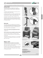
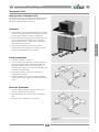
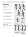
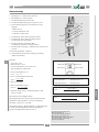
Transport / Lift
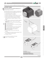
General rules, Transport / Lift
The machine must only be transported / lifted by trained
personnel. All instructions must be observed to avoid
machinery damage and personal injury.
Transport
TRANSPORT / LIFT
1. If the machine will be transported exposed to weather
and wind: Treat all components that could rust with a
rust preventer. Wrap the machine in plastic foil.
2. If the machine will be transported a longer distance or
on uneven ground: Fix the machine to a transport
pallet with PET straps or tension straps. Transport /
lift the pallet with a fork lift.
3. Granulator with wheels: If the machine will be
transported a shorter distance on even, dry ground:
Transport the granulator with its wheels.
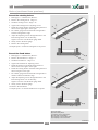
Lift the granulator
1. Close the granulator. >Page 6:4.
2. Use a fork lift. Insert the forks as shown in figure on
the right. Adjust the forks to maximum width. The
forks must tangent the inside of the granulator’s
machine shoes / wheels to prevent the granulator from
overbalancing when lifted.
3. Check that no cables or any parts of the safety
equipment are pinched.
4. Lift the granulator. For information about machine
weight, please refer to page 2:1 ”Technical specifications”.
Store the granulator
(A)
1. Treat all components that could rust with rust preventer for long-term rust protection.
2. Store the machine in a dry area with even temperature.
3. Rotate the rotor manually every 3 months.
(B)
(A)= Machine shoe
(B)= Wheels
INSTRUCTION MANUAL UGG023-0107
3:1
CGW Granulator
4. INSTALLING
Before first start
General rules, Installing
1. Read page 1:2 “Safety rules, During installing”.
2. Read all of chapter 4 before continuing installing.
3. Sign the completed installation, in the end of this chapter.
Reception inspection
1. Check the packing slip to ensure that the delivery is
complete.
2. Check that the machine has not been damaged during
transport. Any damage must be reported to the
forwarding agents.
Put the machine in place
INSTALLING
1. Please refer to the layout for required space. >Page
2:3 “Layout”.
2. Transport / lift the machine to its working area.
>Page 3:1 “Transport / Lift”.
3. Check that the machine stands horizontal and steady.
Remove the rust preventer
Un-painted components are treated with rust preventer
before delivery and transport. Remove the rust preventer
before installing and operating the machine.
1. Read page 7:6 “Cleaning”.
2. Clean following parts inside and outside: Hopper,
Granule bin, Screen box and Screen. Use a low
aromatic alkaline degreaser or a gentle solvent. Wipe
clean with lint-free rags.
Check the knife clearance
1. Check the knife clearance. >Page 7:8 point 13.
Technical specifications
1. Fill in correct information on page 2:1 “General data,
Supplied machine” so that the data corresponds with
the machine sign on your supplied machine.
2. Mark the correct alternatives on page 2:1 “General
data, CGW-series” so that the data corresponds with
your supplied machine.
3. Sign the personnel responsible for the machine’s
service and safety on page 2:1.
Continued
INSTRUCTION MANUAL UGG023-0107
4:1
CGW Granulator
4. INSTALLING
Beforefirststart(continuedfromprevious)
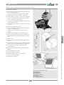
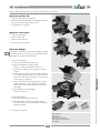
Installthehopper
A granulator with a heavy voluminous hopper may (due
to lack of space during transport) be delivered with
uninstalled hopper and/or inlet.
The following instructions only applies to granulator that
have been delivered with uninstalled hopper and/or inlet.
6.
7.
8.
9.
Put the machine in place. >Page 4:1.
Open the enclosure (-K). >Page 6:1.
Open the cutter housing. >Page 6:2 point 1–3 & 5–8.
Install two M16 lifting eyes on top of the hopper.
Install a lifting strop in the lifting eyes. Make sure
that lifting strop have sufficient capacity to lift the
hopper.
Lift the hopper on top of the cutter housing. Align the
hopper’s hinge brackets with the cutter housing’s
hinge holes.
Note! The front hinge holes is to be used on granulator with cutter housing 1st.
Note! The rear hinge holes is to be used on granulator
with cutter housing 5th.
Note! The front hinge holes can be used on granulator with cutter housing 5th if the granulator is
provided with enclosure “Front position”.
>Page 9:19 “Enclosure”.
Lower the hopper so that it rests on the cutter
housing.
Fix the hopper on the cutter housing. Install the clevis
pins, the washers and the split pins.
The hopper is fixed.
(A)
(B)
INSTALLING
1.
2.
3.
4.
5.
(D)
(C)
The instruction continues on next page.
>Page 4:3 “Install the hopper”.
(E)
(F)
(A) = Lifting eye
(B) = Screw holes, Lifting eye
(C) = Hinge bracket, Hopper
(D) = Clevis pin & Split pin, Hinge holes
(E) = Rear hinge hole, Cutter housing 5th
(F) = Front hinge hole, Cutter housing 1st
Continued
INSTRUCTION MANUAL UGG023-0107
4:2
CGW Granulator
4. INSTALLING
Before first start (continued from previous)
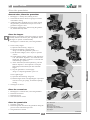
Install the hopper
(F)
(B)
(G)
INSTALLING
10.Before the jack can be installed, the granulator must
be connected to the mains.
>Page 4:4 “Connect the granulator to the mains”.
11.Lift the hopper as shown in figure on the right.
12. Operate the jack. >Page 6:3 “Open a heavy hopper”
point a–f. Adjust the jack so that it aligns with the
holes in the hopper’s jack bracket.
13.Fix the jack on the hopper. Install the clevis pin, the
washer and the split pin.
14. Close the hopper. >Page 6:4 “Close a heavy hopper”
point a–d.
15.Remove the hopper’s eye bolts.
16.Connect the safety switch to the electrical cabinet.
>Page 2:15 “Safety switch”.
>Please refer to the separate electrical circuit
diagram.
17.Install two M12 lifting eyes on top of the inlet.
18.Install a lifting strop in the lifting eyes. Make sure
that lifting strop have sufficient capacity to lift the
inlet.
19. Lift the inlet.
20.Remove the inlet’s handle, the under plate and the
absorber.
21.Move the inlet towards the hopper. Adjust the inlet so
that the inlet’s clasps fitinto the holes in the hopper.
22.Fix the inlet on the hopper. Tighten the inlet’s
tightening screws.
23.Install the inlet’s absorber, the under plate and the
handle.
24. Remove the inlet’s eye bolts.
25.Check the flap(s). >Page 7:1.
26.Install the funnel / feed tray (if supplied).
>Page 2:13 “Inlet / Hopper”.
27.The hopper is installed.
(A)
(G)
(I)
(H)
(E)
(D)
(C)
(A)= Jack bracket, Hopper
(B)= Clevis pin, Split pin, Washer, Jack
(C)= Handle, Inlet
(D)= Under plate, Inlet
(E)= Absorber, Inlet
(F)= Screw holes, Lifting eyes
(G)= Clasp, Inlet
(H)= Clasp hole, Hopper
(I) = Tightening screws, Inlet
INSTRUCTION MANUAL UGG023-0107
4:3
CGW Granulator
4. INSTALLING
Electrical connection
General rules, Electrical connection
1. Read page 4:1 “General rules, installing”
2. The granulator must be disconnected from the mains
before electrical repairs or installing is began.
3. The machine must be installed in accordance to EN
954-1 Category 3. This means that all cables must be
installed so that they will not get damaged during
operation.
4. When replacing electrical components, only use
CONAIR original spare parts. >Page 9:1 “Spare
parts”.
Emergency stop
INSTALLING
1. Read page 4:4 “General rules, Electrical connection”
2. Check that the supplied emergency stop is within
reach at all positions in the machine’s workplace.
3. If the supplied emergency stop is not accessible from
all positions in the workplace, the machine must be
provided with further emergency stops.
Level switch (optional)
1. Adjust the level switch. >Page 7:3.
Current relay (optional)
1. Adjust the current relay. >Page 7:4.
Connect the granulator to the mains
1. Read page 4:4 “General rules, Electrical connection”
2. Check the phase sequence of the electric mains with a
phase sequence display. The granulator is connected
for a right-hand turning field. The electric circuit
diagram specifies the connection voltage (Volt) and
fuse size (Ampere).
3. Connect the granulator to the mains.
INSTRUCTION MANUAL UGG023-0107
4:4
CGW Granulator
4. INSTALLING
Start the granulator
1. Check that all actions in page 4:1–4:4 are done.
2. Close the granulator. >Page 6:4.
3. Start the granulator. >Page 5:1.
Check immediately after first start
INSTALLING
1. Check that the rotating direction of the granulator
motor corresponds to the arrow on the motor.
2. Additional suffix -U (Blower):
Check that the blower’s rotating direction corresponds
to the arrow on the blower.
The blower is functioning even when the rotation
direction is wrong, but if the blower’s rotating
direction is wrong the blower’s capacity decreases
considerably.
3. If the rotating direction is wrong:
a) Stop the granulator. >Page 5:1.
b) Read page 4:4 “General rules, Electrical connection”.
c) Switch over two incoming phases.
d) Start the granulator. >Page 5:1.
4. Additional suffix -B (Band conveyor).
Check the band conveyor. >Page 7:5.
5. Check the emergency stop(s). >Page 7:1.
6. Check the safety equipment. >Page 7:2.
Check five hours after first start
1. Stop the granulator. >Page 5:1.
2. Check the knife clearance. >Page 7:8 point 14.
3. Check the knives tightening torque.
>Page 7:8 point 10 ”Install the fixed knives”.
>Page 7:9 point 10 ”Install the rotating knives”.
4. Check the drive belt(s). >Page 7:13.
Installing complete
The machine has been installed and checked in accordance with the instructions in chapter 4.
Date: ......... / ......... 20 ......................................................
Name:..................................................................................
INSTRUCTION MANUAL UGG023-0107
4:5
CGW Granulator
5. START / STOP
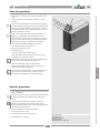
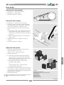
Start the granulator
(A)
(B)
(C)
(E)
(D)
START / STOP
1. Read page 1:2 “Safety rules, During start and operation”
2. Check that there is no material in hopper or cutter
housing.
Important! The granulator must not be started if there
is material left in the hopper and cutter housing. When
starting, remaining material may brake the rotor and
overload the motor. The overload protection will trip
and the granulator will stop.
Important! Granulator with additional suffixes -U
(Blower). A granulator with blower must not be
started if there is material left in granule bin, outlet
pipe or blower. When starting, remaining material in
the blower, outlet pipe or granule bin can cause
serious and irreparable damage to the blower.
3. Put the main switch in position “1”.
4. Reset the emergency stop(s).
5. Standard CGW
Press the button “Reset safety relay”.
When the Reset safety relay-button has lit up, the
granulator is ready to be started.
If the button “Reset safety relay” do not light up, the
safety relay has to be checked. >Page 7:3.
6. Start the granulator. Press the start-button.
7. When the start-button has lit up, the granulator is
started and ready for operation.
Information! If the granulator or optional equipment
does not start once the above points have been
attended to, read page 7:15 “Troubleshooting”.
Stop the granulator
1. Stop feeding material. Wait until all material has been
fully granulated.
Important! Never stop the granulator until all material
in hopper and cutter housing has been fully granulated.
Important! Granulator with additional suffix -U
(Blower). A granulator with blower must not be
stopped until all material have been transported out of
the granule bin and blower.
2. Stop the granulator. Press the stop-button.
3. Press the emergency stop.
4. Lock the main switch in position “0”.
5. The granulator is stopped.
INSTRUCTION MANUAL UGG023-0107
5:1
(A)= Start-button
(B) = Stop-button
(C)= Emergency stop
(D) = Main switch
(E)= Button, Reset safety relay
CGW Granulator
6. OPEN / CLOSE
Open the granulator
General rules, Open the granulator
1. Read page 1:3 ”Safety rules, During service”.
2. Additional suffix -B (Band conveyor): Remove the
band conveyor.
3. Granulator with feed tray: Fold the feed tray up.
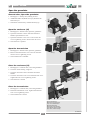
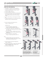
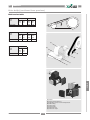
Open the enclosure (-K)
(B)
1. Read page 6:1“General rules, Open the granulator”
2. Open the enclosure’s door/s. Pull the enclosure’s
handle. Open the door/s 180°
3. Open the enclosure’s rear cover. Unscrew the rear
cover’s tightening screws. Remove the rear cover.
4. The enclosure is opened.
(A)
Open the transmission
1. Read page 6:1“General rules, Open the granulator”
2. Remove the transmission cover. Unscrew the transmission cover’s tightening screws.
3. The transmission is available.
(C)
1. Read page 6:4 “General rules, Close the granulator”
2. Close the cutter housing. >Page 6:5.
3. Close the enclosure’s door/s. Pull the enclosure’s
handle.
4. Close the enclosure’s rear cover. Install the rear cover.
Tighten the rear cover’s tightening screws.
5. The enclosure is closed.
(E)
(F)
(G)
(D)
Close the transmission
1. Read page 6:4 “General rules, Close the granulator”
2. Install the transmission cover. Tighten the transmission cover’s tightening screws.
3. The transmission is closed.
(E)
(A)= Feed tray, Inlet
(B)= Rear cover, Enclosure
(C)= Cover, Transmission
(D)= Door, Enclosure
(E)= Front, Cutter housing
(F)= Handle, Cutter housing
(G)= Catch, Cutter housing
Continued
INSTRUCTION MANUAL UGG023-0107
6:1
CGW Granulator
OPEN / CLOSE
Close the enclosure (-K)
6. OPEN / CLOSE
Open the granulator (continued from previous)
Open the cutter housing
1. Read page 6:1“General”
2. Granulator with additional suffix -K (Enclosure):
Open the enclosure’s door/s. >Page 6:1 point 2.
3. Remove the granule bin’s quick coupling ring.
>Page 6:3 image (A).
4. Release the switch key from the safety switch.
>Page 2:15 “Safety switch”
Standard CGW:
a) Start the granulator’s current supply.
>Page 5:1 “Start the granulator” point 3–4.
b) Check that the safety switch’s diode light is lit.
(The safety switch’s diode light is lit as the rotor
stands still.
c) Remove the switch key from the safety switch.
Pull the switch key’s handle down. Swing the
switch key’s handle to the side.
d) Stop the granulator’s current supply.
>Page 5:1 “Stop the granulator” point 3–4.
Solo:
a) Unscrew the safety switch’s star knob. Unscrew
until the switch key is fully released from the
safety switch.
(A)
(B)
(E)
(F)
(C)
(D)
(G)
(H)
(H)
(I)
5. Loosen the locking bolts. Use a telescope wrench. A
telescope wrench is enclosed on delivery.
6. Pull the cutter housing’s catch straight out and then
down. Check that the locking bolts can pass through
the holes in the lock plate.
7. Swing the cutter housing’s front aside. Pull the cutter
housing’s handle until the cutter housing is fully
opened.
(I)
(J )
(J )
Standard
CGW model
CGW
Solo
model
8. The cutter housing is opened.
CGW
Solo
model
(A)= Safety switch, Standard CGW
(B)= Diode light, Standard CGW
(C)= Switch key, Standard CGW
(D)= Handle, Switch key, Standard CGW
(E)= Safety switch, CGW Solo
(F)= Switch key, Solo
(G)= Star knob, Solo
(H)= Locking bolts
(I) = Lock plate
(J)= Catch, Cutter housing
Continued
INSTRUCTION MANUAL UGG023-0107
6:2
CGW Granulator
OPEN / CLOSE
Standard
CGW model
6. OPEN / CLOSE
Open the granulator (continued from previous)
Open the granule bin
1. Open the cutter housing. >Page 6:2.
2. Remove the granule bin. Move the granule bin along
the grooves in the cutter housing’s front.
3. The granule bin is opened.
Open the screen box
1. Open the granule bin.
2. Remove the screen.
3. Remove the screen box.
4. The screen box is opened.
(B) (A)
(C)
Open the hopper
Information! A granulator with a heavy hopper is opened
/ closed by means of an electric jack. A granulator with a
light hopper is opened /closed manually.
(D)
1. Open a heavy hopper:
a) Open the cutter housing. >Page 6:2.
b) Start the granulator’s current supply.
>Page 5:1 “Start the granulator” point 3–4.
c) Put the knob ”Hopper, Close / Open” in position
“Open”.
d) Check that the buttons “Operate1” and “Operate 2”
is lit. (The button “Operate 1” is lit when the rotor
stands still. The button “Operate 2” is lit when the
cutter housing is opened.)
e) At the same time (two hand operation), press the
buttons ”Operate 1” and ”Operate 2”. Keep the
buttons depressed until the jack has fully opened
the hopper.
f) Stop granulator’s current supply.
>Page 5:1 point 3-4.
Open a light hopper:
a) Open the cutter housing. >Page 6:2.
b) Push the hopper upwards. The light hopper is
provided with one or two gas springs, to facilitate
opening / closing.
(E) (F)
OPEN / CLOSE
(G)
(B)
(C)
2. The hopper is opened.
(D)
(A)= Quick coupling ring, Granule bin
(B)= Granule bin
(C)= Screen
(D)= Screen box
(E)= Front, Cutter housing
(F)= Magnet switch, Granule bin
(G)= Hopper
INSTRUCTION MANUAL UGG023-0107
6:3
CGW Granulator
6. OPEN / CLOSE
Close the granulator
General rules, Close the granulator
1. Read page 1:3 “Safety rules, During service”.
2. Check that all surfaces which are going to touch are
clean before closing.
3. Additional suffix -B (Band conveyor): After closing
the granulator, put the band conveyor close to the
granulator’s hopper / inlet.
4. Granulator with feed tray: After closing the granulator, fold the feed tray down.
(B) (A)
Close the hopper
Information! A granulator with a heavy hopper is opened
/closed by means of an electric jack. A granulator with a
light hopper is opened / closed manually.
(C)
1. Read page 6:4 “General rules, Close the granulator.
2. Close a heavy hopper:
a) Open the cutter housing. >Page 6:2.
b) Start the granulator’s current supply.
>Page 5:1 “Start the granulator” point 3–4.
c) Put the knob “Hopper, Close / Open” in position
”Close”.
d) Check that the buttons “Operate1” and “Operate 2”
is lit. (The button “Operate 1” is lit when the rotor
stands still. The button “Operate 2” is lit when the
cutter housing is opened.)
e) At the same time (two hand operation), press the
buttons ”Operate 1” and ”Operate 2”. Keep the
buttons depressed until the jack has closed the
hopper.
f) Stop the granulator’s current supply.
>Page 5:1 “Stop the granulator” point 3–4.
(E) (F)
Close a light hopper:
a) Open the cutter housing. >Page 6:2.
b) Pull the hopper down. The light hopper is provided
with one or two gas springs, to facilitate opening /
closing.
OPEN / CLOSE
(D)
(G)
2. The hopper is closed.
Close the screen box
1. Read page 6:4 “General rules, Close the granulator.
2. Install the screen box.
3. Install the screen.
4. The screen box is closed.
Close the granule bin
1. Close the screen box.
2. Install the granule bin. Move the granule bin along the
grooves in the cutter housing’s front.
3. The granule bin is closed.
(B)
(C)
(D)
(A)= Quick coupling ring, Granule bin
(B)= Granule bin
(C)= Screen
(D)= Screen box
(E)= Front, Cutter housing
(F)= Magnet switch, Granule bin
(G)= Hopper
Continued
INSTRUCTION MANUAL UGG023-0107
6:4
CGW Granulator
6. OPEN / CLOSE
Close the granulator (continued from previous)
Close the cutter housing
1. Read page 6:4 “General, Close the granulator”
2. Granulator with additional suffix -K (Enclosure):
Close the enclosure’s door/s. >Page 6:1 point 2.
3. Close the hopper. >Page 6:4.
4. Close the granule bin. >Page 6:4.
5. Close the cutter housing’s front. Let the locking bolts
pass through the holes in the lock plate. Push the
cutter housing’s handle until the cutter housing is
closed.
6. Pull the cutter housing’s catch straight out and then
up.
7. Tighten the locking bolts. Use a telescope wrench. A
telescope wrench is enclosed on delivery.
8. Fit the switch key into the safety switch.
>Page 2:15 “Safety switch”.
Solo:
a) Tighten the safety switch’s star knob. Fit the
switch key into the safety switch. Keep screwing
the star knob until it stops moving.
Standard CGW
(A)
(B)
(E)
(F)
(C)
(D)
(G)
(H)
(H)
(I)
(J )
(I)
(J )
Standard CGW
CGW
Solo
9. Install the granule bin’s quick coupling ring.
>Page 6:4 image (A).
10.Check that the granule bin’s magnet switch has mated
with the transmission cover’s magnet switch.
>Page 2:15 “Magnet switch.
11.The cutter housing is closed.
CGW
Solo
(A)= Safety switch, Standard GCW
(B)= Diode light, Standard GCW
(C)= Switch key, Standard GCW
(D)= Handle, Switch key, Standard GCW
(E)= Safety switch, CGW Solo
INSTRUCTION MANUAL UGG023-0107
6:5
(F)= Switch key, Solo
(G)= Star knob, Solo
(H)= Locking bolts
( I ) = Lock plate
(J)= Catch, Cutter housing
CGW Granulator
OPEN / CLOSE
Standard CGW:
a) Start the granulator’s current supply.
>Page 5:1 “Start the granulator” point 3–4.
b) Check that the safety switch’s diode light is lit.
(The safety switch’s diode light is only lit when the
rotor stands still).
c) Swing the switch key’s handle forward. Pull the
switch key’s handle up. Fit the switch key into the
safety switch.
d) Stop the granulator’s current supply.
>Page 5:1 “Stop the granulator” point 3–4.
7. SERVICE
Generalrules,Service
1. Readpage1:3”Safetyrules,Duringservice”.
2. Check/servicethemachineinaccordancewiththe
serviceschedule.
3. Alwayssigninspections/serviceinaservicereport.
Copytheoriginalservicereport,signitandsaveitin
aseparateservicebinder.>Page8:1.
Emergencystop(s)
1. Readpage7:1“Generalrules,Service”
2. Readpage2:14”Emergencystop(s)”.Checkthe
emergencystop(s):
a) Startthegranulator.>Page5:1.
b) Stopfeedingmaterial.Waituntilallmaterialhas
beenfullygranulated.
c) Presstheemergencystop.Checkthatthegranulatorstops.Ifthegranulatorstops,theemergency
stopcanberesetandthegranulatorcanbe
restarted.
d) Danger!Ifthegranulatorcontinuesworking,
althoughtheemergencystophasbeenpressed,the
granulatormustbestoppedmanuallyatonce.
>Page5:1.Thereisaseriousriskofpersonal
injury.Contactthepersonnelresponsibleforthe
machine’sserviceandsafety.
Serviceschedule
Interval
Doneby
Check
Once
everyday
Operator
•Emergencystop(s)
•Flap(s)
Once
every
week
Trained
personnel
•Electricalcomponents
•Safetyequipment
•Safetyrelay
Once
every
month
Trained
personnel
•Knifesharpness
•Knifeclearance
•Screen
Once
every6th
month
Trained
personnel
•Drivebelt(s)
(A)
(B)
Flap(s)
Solo
SERVICE
1. Readpage7:1“Generalrules,Service”
2. Readpage2:13”Flap(s)”
3. Checktheflap(s).Changeasnecessary.
(B)
Lubrication
Allbearingsinthegranulatorislubricatedforlifeand
mustnotbere-greased.
Standard CGW model
(A) = Emergency stop(s)
(B) = Flap(s)
INSTRUCTION MANUAL UGG23-0107
7:1
CGW Granulator
7. SERVICE
Safety equipment
1. Read page 7:1 “General rules, Service”
2. Read page 2:12 “General rules, Safety equipment”.
Check that all parts of the safety equipment are
installed.
3. Read page 2:15 “Safety switch”. Check that safety
switch(es) is/are functioning:
a) Start the granulator. >Page 5:1.
b) Stop feeding material. Wait until all material has
been fully granulated.
c) Standard CGW:
Gently try to release the switch key from the safety
switch. >Page 6:2 point 4 c “Standard CGW”.
Note! It should be impossible to pull down the
switch key’s handle.
Danger! If it is possible to release the switch key
from the safety switch although the granulator is
running, the granulator must be stopped manually
at once. >Page 5:1. There is a serious risk of
personal injury. Contact the personnel responsible
for the machine’s service and safety. (A)(B)(C)
Solo
Solo
c) Solo:
Release the switch key from the safety switch.
>Page 6:2 point 4 a “Solo”.
Check that the granulator stops.
Danger! If the granulator continues working,
although the switch key has been released from the
safety switch, the granulator must be stopped
manually at once. >Page 5:1. There is a serious
risk of personal injury. Contact the personnel
responsible for the machine’s service and safety.
SERVICE
4. If the safety switch(es) is/are functioning the granulator can be operated again. Electrical components
1. Read page 7:1 “General rules, Service”.
2. Read page 4:4 “General rules, Electrical connection”
3. Check all the cables. If there are any damaged or
loose cables, connectors or components, authorised
personnel must be called at once to do repairs.
(D)(E)
Standard CGW
(A)= Star knob, Solo
(B)= Safety switch, Solo
(C)= Switch key, Solo
(D)= Safety Switch, Standard CGW
(E)= Switch key, Standard CGW
INSTRUCTION MANUAL UGG23-0107
7:2
CGW Granulator
7. SERVICE
Safety relay
1.
2.
3.
4.
Read page 7:1 “General rules, Service”.
Read page 2:16 “ Reset safety relay”.
Reset the emergency stop(s).
Check that the main switch is in position “1”.
Danger! Do not put the main switch in position “0”. (When the main switch is put in position “0” the
safety relay-button resets, but a possible failure
remains).
5. Press the button “Reset safety relay”.
6. Check that the button “Reset safety relay” is lit.
If the button “Reset safety relay” lights up, the safety
relay is functioning and the granulator can be started.
Danger! If the button “Reset safety relay” do not light
up, this indicates a safety failure. There is a serious
risk of personal injury. Contact the personnel responsible for the machine’s service and safety.
(A)
Reset
safety relay
(B)
Level switch
1.
2.
3.
4.
Read page 7:1 “General rules, Service”.
Read page 2:17 “Level switch”
Open the granule bin. >Page 6:3.
Adjust the level switch’s sensitivity.
Level switch, paddle type:
a) Unscrew the level switch’s cover.
b) Adjust the torsion spring. Use a pair of needle
nosed pliers or a tweezers.
To decrease the sensitivity – Move the torsion
spring to the left.
To increase the sensitivity – Move the torsion
spring to the right.
c) Close the level switch’s cover.
5. Close the granule bin. >Page 6:4.
6. Close the cutter housing. >Page 6:5.
SERVICE
(C)
(A)= Button, “Reset safety relay”
(B)= Level switch, Paddle type
(C)= Torsion spring, Paddle switch
INSTRUCTION MANUAL UGG23-0107
7:3
CGW Granulator
7. SERVICE
Current relay
1.
2.
3.
4.
5.
Read page 7:1 “General rules, Service”.
Read page 2:18 “Current relay”
Set the wanted reaction time (T1).
Set the time delay during start up (T2) to 0 sec.
Check following points in the electrical circuit
diagram:
• Rated current.
• Current transformer size.
• Y/D-start or Direct-start.
(A)
(B)
(C)
(D)
6. Calculate the limit value in Ampere (LVA).
7. Calculate the limit value percentage (LV%). Set the limit value percentage.
8. Set the hysteresis percentage (H%). Calculate the hysteresis in Ampere (HA).
9. Set the function settings to “Memory off” and “Excess
current”.
10.Start the granulator. >Page 5:1.
11.Check that the current relay setting is satisfying.
Adjust as necessary.
(E)
(F)
(G)
Example:
(G)
• T1 is set to 3 sec.
• Rated current is 15 A.
• Current transformer’s size is 30 (/1A).
• The granulator is Y/D-started.
Memory On
Undercurrent
Memory Of
Excess current
• LVA is calculated to 8.7 A
8.7 A = 15 / √3
• LV% is calculated and set to 29%
29% = 8.7 x 100
30
• H% is set to 20%.
LVA (Y/D-start) = Rated current / √3 • HA is calculated to 6.96 A.
6.96 A = 8.7 - (8.7 x 20)
100
• Function setting is set to ”Without memory” and
”Excess current”.
( LVA x 100 ) LV% =
Current transformer size
LVA – ( LVA x H% ) HA =
100
The settings in the example means:
During operation, the relay will trip and stop the feed
equipment if the granulator’s current consumption
exceeds 8.7 A for over 3 seconds.
The function setting “Without memory” enables the relay
to restart the feed equipment when the granulator’s
current consumption has sunk to 6.96 A.
(A)= Limit value percentage, LV%
(B)= Reaction time, T1
(C)= Time delay during start up, T2
(D)= Hysteresis percentage, H%
(E)= Indicator light, Current consumption
(F)= Indicator light, Current relay
(G)= Function settings
INSTRUCTION MANUAL UGG23-0107
7:4
CGW Granulator
SERVICE
LVA (Direct-start) = Rated current
7. SERVICE
Bandconveyor
1.
2.
3.
4.
Readpage7:1“Generalrules,Service”
Readpage2:7“Additionalsuffix-B”.
Checktheband’srotationdirection.
Iftherotationdirectioniswrong:
a) Stopthegranulator.>Page5:2.
b) Readpage4:4“Generalrules,Electricalconnection”.
c) Switchovertwoincomingphases.
d) Startthegranulator.>Page5:1.
Checkthatthebandrunsstraight.
Ifthebandrunsobliquely:
a)Stopthebandconveyor.
b) Openthecoversattheband’sturndrum.
c) Adjusttheband’sadjustingscrewsa1/4turnata
time.
d) Startthebandconveyor.Letthebandrunforafew
minutes.Checkthatthebandrunsstraight.
Ifthebandstillrunsobliquely,repeatpoint4a–d
untilthebandrunsstraight.
Note!Theband’slengthhasatoleranceof1%.The
adjustingscrews’tighteningtorquemustnever
exceed5Nm.
1424-KB
(B)
5. Closethecoversattheband’sturndrum.
SERVICE
(C)
(D)
(A) = Star knob
(B) = Turn drum, Band conveyor
(C) = Cover, Turn drum
(D) = Adjusting screws, Band conveyor
INSTRUCTION MANUAL UGG23-0107
7:5
CGW Granulator
7. SERVICE
Cleaning 1. Read page 7:1 “General rules, Service”.
2. When granulating material that generates dust:
a) Clean the granulator’s parts once every day or at
least once every week.
(B)
(A)
In normal operation:
a) Clean the granulator parts at colour change or at
least once every 300 hours.
3. Open the granulator. >Page 6:1.
4. Clean the granulator parts. Use a vacuum cleaner.
Clean following parts inside and outside: Funnel /
Feed tray, Inlet, Hopper, Flap(s), Cutter housing,
Screen, Screen box, Granule bin and Enclosure.
Important! Do not use compressed air and a blow gun,
since granulate and plastic residue could be blown
into safety switches. Granulate and plastic residue
material blown to the floor makes the floor slippery.
(C)
(E)
(D)
5. Additional suffix -U (Blower). Clean the blower,
outlet pipe and granule bin very carefully. Use a
vacuum cleaner.
Important! When starting, remaining material in the
blower, outlet pipe or granule bin can cause serious or
irreparable damage to the blower.
6. Additional suffix -B (Band conveyor). Clean the band.
Use a gentle detergent. Strong detergents can damage
the band. Wipe clean with lint-free rags.
7. Close the granulator. >Page 6:4.
(H)
Important! If the rotor is stuck, rotate the rotor in the
reverse direction, if necessary tap carefully with a
piece of wood. Never use any metal object when you
try to release the rotor.
(G)
Important! If the hopper, cutter housing, screen box
and/or granule bin are filled with compact, hardened
plastic residue - a so-called melt-down - the local
Conair distributor or Conair Main Office must be
contacted for service.
SERVICE
(F)
(A)= Feed tray
(B)= Flap(s)
(C)= Inlet
(D)= Hopper
(E)= Cutter housing
(F)= Granule bin
(G)= Screen box
(H)= Screen
INSTRUCTION MANUAL UGG23-0107
7:6
CGW Granulator
7. SERVICE
Knives
General rules, Knives
6.
7.
8.
9.
(5th)
(5th)
Remove the rotating knives
1.
2.
3.
4.
5.
(2nd)
(2nd)
1. Read page 7:1 “General rules, Service”.
2. Read page 2:8 “Rotor” and “Rotating knives”.
3. Read page 2:9 “Cutter housing” and “Fixed knives”
4. Read page 2:10 “Knife grinding fixture”, “Knife
clearance” and “Knife setting fixture”.
cutteR HOUSING
restricted tangential; 1st
cutteR HOUSING
super tangential; 5th
Read page 7:7 “General rules, Knives”.
Open the cutter housing. >Page 6:2.
Open the hopper. >Page 6:3.
Remove the knives on one knife row at the time.
Rotate the rotor to an appropriate position. Lock the
rotor’s position with a piece of wood.
Unscrew the rotating knife’s tightening screws.
Remove the rotating knife’s washers.
Remove the rotating knife.
Repeat point 5–8 until all rotating knives have been
removed.
(E)
(2nd)
(D)
(1st)
(A)
(B)
(C)
(1st)
Remove the fixed knives
1. Remove the rotating knives.
2. Remove the fixed knife on one side at the time.
3. Mark the fixed knife’s tightening screws with a
marker pen.
Note! The tightening screws must not be mixed up
when re-installing.
4. Unscrew the fixed knife’s tightening screws.
5. Mark the fixed knife’s support rule with a marker pen. Note! The support rules must not be mixed up when
reinstalling.
6. Remove the fixed knife’s support rule.
7. Remove the fixed knife.
8. Repeat point 3–7 until all fixed knives have been
removed.
(5th)
(C)
(B)
SERVICE
(A)
Mark the rotating knife with a marker pen:
= Knife clearance is correct.
= Tightening screws are correctly torqued.
= Knife clearance has been re-checked and is correct.
(A)= Rotating knife
(B)= Washer, Rotating knife
(C)= Tightening screw, Rotating knife
(D)= Fixed knife
(E)= Tightening screw, Fixed knife
Continued
INSTRUCTION MANUAL UGG23-0107
7:7
CGW Granulator
7. SERVICE
Knives (continued from previous)
Install the fixed knives
(2nd)
(5th)
(5th)
cutteR HOUSING
Restricted tangential; 1st
cutteR HOUSING
super tangential; 5th
(E)
(2nd)
(D)
(1st)
(A)
(B)
(C)
(1st)
(5th)
(C)
(B)
(A)
SERVICE
Read page 7:7 “General rules, Knives”.
Remove the fixed knives. >Page 7:7.
Preset the fixed knives. >Page 7:10.
Install the front fixed knife (2nd).
Rotate the rotor to an appropriate position. Lock the
rotor’s position with a piece of wood.
6. Check that the fixed knife’s knife seat is clean.
7. Install the fixed knife. Press the fixed knife firmly
against the cutter housing’s grub screws. Note! The setting of the grub screws must never be
changed, they are permanently set and glued.
8. Install the fixed knife’s support rule. Note! Check that the appropriate support rule is
installed. The support rules must not be mixed up.
9. Install the fixed knife’s tightening screws.
Note! Check that the appropriate tightening screws are
installed. The tightening screws must not be mixed up.
Note! Note! The tightening screws which tightens the
rear fixed knife (1st) must be provided with washers.
10.Tighten the fixed knife’s tightening screws. Tightening torque 280 Nm. Note! Every second time knives are changed, the
knives must be installed with new tightening screws.
11.The front fixed knife (2nd) is installed. Before the
remaining rear fixed knife/knives can be installed, all
rotating knives must be installed. >Page 7:9.
12.When all rotating knives have been installed, the
remaining fixed knife/knives can be installed.
13. Repeat point 5–10 above. Then proceed to point 14.
14.Check the knife clearance. Release the rotor. Rotate
the rotor to an appropriate position. Put a feeler gauge
between the rear fixed knife and the rotating knife.
Put the feeler gauge alternately to the right, to the left
and in the middle. Correct knife clearance is
0.008 – 0.016 in {0.20 – 0.40 mm}. Check the knife
clearance against one knife row at the time.
If the knife clearance is correct: Mark the rotating
knife with a marker pen. Draw one more line through
the circle:
(If the knife clearance is wrong: Adjust the adjusting
screws until correct knife clearance is reached. >Page
7:10 “Preset the fixed knife”.
Repeat point 14 until all rotating knives have been
marked:
15. If the cutter housing has three fixed knives, proceed
to point 13. If the cutter housing has two fixed knives:
Proceed to point 16.
16.All fixed knives (and all rotating knives) are installed.
(2nd)
1.
2.
3.
4.
5.
Mark the rotating knife with a marker pen:
= Knife clearance is correct.
= Tightening screws are correctly torqued.
= Knife clearance has been re-checked and is correct.
(A)= Rotating knife
(B)= Washer, Rotating knife
(C)= Tightening screw, Rotating knife
(D)= Fixed knife
(E)= Tightening screw, Fixed knife
Continued
INSTRUCTION MANUAL UGG23-0107
7:8
CGW Granulator
7. SERVICE
Knives (continued from previous)
Install the rotating knives
(2nd)
(2nd)
1. Install the front fixed knife (2nd).
>Page 7:8 point 1–11.
2. Preset the knives. >Page 7:10.
3. Install one rotating knife at the time.
4. Rotate the rotor to an appropriate position. Lock the
rotor’s position with a piece of wood.
5. Check that the rotating knife’s knife seat is clean.
6. Press the rotating knife firmly against the bottom of
the knife seat.
7. Install the rotating knife’s washers.
Note! The washers must be installed so that they fully
cover the knife’s screw holes.
8. Loosely tighten the rotating knife’s tightening screws. Note! Every second time knives are changed, the
knives must be installed with new tightening screws.
9. Check the knife clearance. Release the rotor. Rotate
the rotor to an appropriate position. Put a feeler gauge
between the rotating knife and the front fixed knife.
Put the feeler gauge alternately to the right, to the left
and in the middle. Correct knife clearance is 0.008 in
– .016 in.
If the knife clearance is correct: Mark the rotating
knife with a marker pen. Draw a circle:
(If the knife clearance is wrong: Adjust the adjusting
screws until correct knife clearance is reached. >Page 7:10 “Preset the rotating knife”.)
10.Tighten the rotating knife’s tightening screws.
Tightening torque 280 Nm. Mark the rotating knife
with a marker pen. Draw a line through the circle:
11.Repeat point 4–10 until all rotating knives have been
installed.
12.When all rotating knives have been installed, the rear
fixed knife/knives can be installed. >Page 7:8 point 12 “Install the fixed knives”.
(5th)
(5th)
cutteR HOUSING
restricted tangential; 1st
cutteR HOUSING
super tangential; 5th
(E)
(2nd)
(D)
(1st)
(A)
(B)
(C)
(1st)
(5th)
(C)
(B)
SERVICE
(A)
Mark the rotating knife with a marker pen:
= Knife clearance is correct.
= Tightening screws are correctly torqued.
= Knife clearance has been re-checked and is correct.
(A)= Rotating knife
(B)= Washer, Rotating knife
(C)= Tightening screw, Rotating knife
(D)= Fixed knife
(E)= Tightening screw, Fixed knife
Continued
INSTRUCTION MANUAL UGG23-0107
7:9
CGW Granulator
7. SERVICE
Knives (continued from previous)
Preset the rotating knives
1.
2.
3.
4.
5.
Read page 7:7 “General rules, Knives”.
Remove the rotating knives. >Page 7:7.
Grind the rotating knives. >Page 7:12.
Tighten the rotating knives’ adjusting screws.
Install the rotating knife in the knife setting fixture as
shown in the upper figure on the right.
6. Put a feeler gauge between the knife setting fixture
and the rotating knife’s edge.
7. Adjust the adjusting screws through the holes in the
knife setting fixture. Use an allen key.
Tighten / unscrew until the feeler gauge binds.
8. Gently remove the feeler gauge.
9. Remove the rotating knife.
10.Repeat point 5–9 until all rotating knives are preset.
(A)
(D)
Preset the fixed knives
1.
2.
3.
4.
5.
(E)
(B)
(A)
(D)
SERVICE
Read page 7:7 “General rules, Knives”.
Remove the fixed knives. >Page 7:7.
Grind the fixed knives. >Page 7:11.
Tighten the fixed knives’ adjusting screws.
Install the distance in the knife setting fixture as
shown in the lower figure on the right.
6. Install the rotating knife in the knife setting fixture as
shown in figure on the right.
7. Put a feeler gauge between the knife setting fixture’s
distance and the fixed knife’s edge.
8. Adjust the adjusting screws through the holes in the
knife setting fixture. Use an allen key.
Tighten / unscrew until the feeler gauge binds.
9. Gently remove the feeler gauge.
10.Remove the fixed knife.
11.Repeat point 6–10 until all fixed knives are preset.
(F)
(C)
(B)
(A)= Feeler gauge
(B)= Knife setting fixture
(C)= Distance, Knife setting fixture
(D)= Hole, Knife setting fixture
(E)= Adjusting screws, Rotating knife
(F)= Adjusting screws, Fixed knife
Continued
INSTRUCTION MANUAL UGG23-0107
7:10
CGW Granulator
7. SERVICE
Knives (continued from previous)
General rules, Grind the knives
1. Read page 7:1 “General rules, Service”.
2. Always begin grinding the worst and most blunt
knife.
3. Grind the knives with accurate precision. It is very
important that the relief angle and the cutting angle
becomes correct. Respect the specified measures.
4. Always cool the knives during grinding. Grind slowly.
Make sure that no heat is developed. Knives that are
overheated when grinded, loose their hardness,
strength and durability. Knives that have been burned
or quenched blue, are irrreparable and must be
discarded.
5. A surface grinder with magnetic table and a grinding
fixture ensures that the cutting angles and the relief
angles become correct.
(B)
(A)
(E) 60 mm
(D) 50 mm
Grind the fixed knives
(C) 90°
(F)
(G)
SERVICE
1. Read page 7:11 “General rules, Grind the knives”
2. Remove the fixed knives. >Page 7:7.
3. Unscrew the fixed knives’ adjusting screws.
4. Install the fixed knife in the knife grinding fixture as
shown in figure on the right. Tighten the fixed knife
with the knife grinding fixture’s tightening screws.
5. Grind the fixed knife’s cutting edge. Use a surface
grinder. A correct cutting angle on the fixed knife is
90°. Grind until all irregularities have disappeared.
6. Remove the knife but keep the settings on the surface
grinder.
7. Measure the fixed knife’s length after grinding.
Note! If the fixed knife’s length is less than 50 mm,
the fixed knife must be discarded and replaced by a
new fixed knife.
(G)
(F)
(A)= Knife grinding fixture
(B)= Tightening screw, Knife grinding fixture
(C)= Cutting angle, Fixed knife
(D)= Minimum length, Grinded fixed knife
(E)= Lenght, New fixed knife
(F)= Cutting edge No1, Reversible fixed knife
(G)= Cutting edge No2, Reversible fixed knife
Continued
INSTRUCTION MANUAL UGG23-0107
7:11
CGW Granulator
7. SERVICE
Knives (continued from previous)
Grind the rotating knives
(E) 50°
(A)
(B)
(C)
(F) 3mm
(G) 55°
(G) 55°
(E) 50°
SERVICE
1. Read page 7:11 ”General rules, Grind the knives”
2. Install the distance in the knife grinding fixture as
shown in the upper figure on the right.
3. Install the rotating knife in the knife grinding fixture
as shown in the upper figure on the right. Install the
knife grinding fixture’s washers. Tighten the rotating
knife with the knife grinding fixture’s tightening
screws.
4. Grind the rotating knife’s second relief angel. Use a
surface grinder. A correct second relief on the rotating
knife is 50°. Grind until all irregularities have
disappeared.
5. Remove the knife but keep the settings on the surface
grinder.
NOTE! All rotating knives must be grinded equally to
maintain the rotor balance. The rotating knives must
have the same measure and weight (within a gramme).
6. Repeat point 2–5 until all rotating knives’ second
relief angles have been grinded.
7. Remove the distance from the knife grinding fixture.
8. Install the rotating knife in the knife grinding fixture
as shown in the middle figure on the right. Install the
knife grinding fixture’s washers. Tighten the rotating
knife with the knife grinding fixture’s tightening
screws.
9. Grind the rotating knife’s cutting edge and first relief
angle. Use a surface grinder. A correct first relief
angle on the rotating knife is 55°. Grind until the first
relief surface becomes 3 mm.
10.Remove the knife but keep the settings on the surface
grinder.
11.Measure the rotating knife’s length after grinding.
NOTE! If the rotating knife’s length is less than 56
mm, the rotating knife must be discarded and replaced
by a new rotating knife.
12.Repeat point 8–11 until all rotating knives’ cutting
angles have been grinded.
3mm (F)
(H) 56 mm
( I ) 66 mm
(A)= Knife grinding fixture
(B)= Tightening screw, Knife grinding fixture
(C)= Distance, Knife grinding fixture
(D)= Cutting edge, Rotating knife
(E)= First relief angle, Rotating knife
(F)= First relief surface, Rotating knife
(G)= Second relief angle, Rotating knife
(H)= Minimum length, Grinded rotating knife
( I )= Length, New rotating knife
INSTRUCTION MANUAL UGG23-0107
7:12
CGW Granulator
7. SERVICE
Drive belt(s)
General rules, Drive belt(s)
1. Read page 7:1 “General rules, Service”
2. Read page 2:11 “Transmission”
3. Open the transmission. >Page 6:1.
(H)
(G)
(E)
Check the drive belts(s)
1. Read page 7:13 “General rules, Drive belt(s)”
2. Check the condition of the drive belt(s). Rotate the
rotor pulley a few turns. Check that the drive belt(s)
is/are intact and does/do not have any cracks.
3. Check the belt tension. Check one drive belt at the
time.
a) Load the drive belt in the middle between the rotor
pulley and the motor pulley. Load the drive belt
with the force specified in the belt tension table on
page 7:14.
b) Measure the deflection depth. Correct deflection
depth is 8 mm.
(F)
(A)
(B)
(F)
(D)
4. Adjust the belt tension / change drive belt(s) as
necessary.
5. Close the transmission. >Page 6:1.
(E)
(C)
(C)
Adjust the belt tension
1. Granulator with additional suffix -K (Enclosure):
Open the enclosure’s rear cover. >Page 6:1 point 3 “Open the enclosure”.
2. Check the drive belt(s).
4. Check that the rotor pulley and the motor pulley are in
line (tolerance 0.5 mm). Check that the motor and the
rotor are parallel. Adjust the motor mounting bracket’s
adjusting screws as necessary.
5. Check the belt tension.
Note! When drive belts have been adjusted they must
be re-checked after 20 hours of operation.
SERVICE
3. a) Adjust the motor mounting bracket’s adjusting
screws. Tighten / Unscrew the right and the left
adjusting screw with equal turns, to ensure that the
motor still will be parallel with the rotor.
b) Decrease the belt tension - Move the motor
mounting bracket upwards. or
Increase the belt tension – Move the motor
mounting bracket downwards.
(A)= Motor
(B)= Motor mounting bracket
(C)= Adjusting screws, motor mounting bracket
(D)= Drive belt(s)
(E)= Rotor pulley
(F)= Motor pulley
(G)= Deflection force
(H)= Deflection depth
Continued
INSTRUCTION MANUAL UGG23-0107
7:13
CGW Granulator
7. SERVICE
Drive belt(s) (continued from previous)
Belt tension table
Deflection
depth
8 mm
10 Hp {7.5 kW}
15 Hp {11 kW}
Old
drive
belt
New
drive
belt
Old
drive
belt
New
drive
belt
50 Hz / 60Hz
N
N
15 N
19 N
(H)
(G)
(E)
Deflection
depth
8 mm
25 Hp {18.7 kW}
40 Hp {29.8 kW}
Old
drive
belt
New
drive
belt
Old
drive
belt
New
drive
belt
50 Hz / 60Hz
23 N
30 N
N
N
(F)
(A)
Deflection
depth
8 mm
50 Hp {37.3 kW}
Old
drive
belt
New
drive
belt
50 Hz / 60Hz
N
N
(B)
(F)
(D)
(E)
(C)
SERVICE
(C)
(A)= Motor
(B)= Motor mounting bracket
(C)= Adjusting screws, motor mounting bracket
(D)= Drive belt(s)
(E)= Rotor pulley
(F)= Motor pulley
(G)= Deflection force
(H)= Deflection depth
INSTRUCTION MANUAL UGG23-0107
7:14
CGW Granulator
7. SERVICE
Troubleshooting
Problem
The granulator
or any optional
equipment does
not start / stops
unexpectedly.
Probable cause
The emergency stop is activated
The granulator / the optional equipment is not
connected to the mains.
Solution
1. Reset the emergency stop(s). >Page 5:1.
1. Connect the granulator to the mains. >Page 4:2.
2. Connect the mains plug on the band conveyor to
the electrical outlet (Band conveyor = optional).
The main switch is in position “0”.
1. Put the main switch in position “1”. >Page 5:1.
The button “Reset safety relay” has not been 1. Press the button “Reset safety relay”. >Page 5:1
pressed.
“Start the granulator”
Screen box, Granule bin, Hopper, Enclosure
1. Close the granulator. >Page 6:2.
and/or optional equipment are not properly
2. Check that all safety switches / star knobs are
closed, or their safety switch(es) / star knob(s)
closed. >Page 2:15 “Safety switch” and “Star
is/are open.
knob”.
The granulator’s overload protection F1 has
1. Reset the overload protection. >Page 2:16
tripped since the granulator has been over“Overload protection”.
loaded.
Before restart:
or
2. Clean the granulator. >Page 7:6.
Band conveyor (optional): The band convey- 3. Check the drive belt(s). Adjust / change drive
or’s overload protection Q3 has tripped since
belts as necessary. >Page 7:13.
the band has stuck or the band conveyor has
4. Check knife sharpness and knife clearance.
been overloaded.
>Page 7:8 point 14.
or
Blower (optional): The blower’s overload
protection Q2 has tripped since the blower
has been overloaded.
The level switch (optional) has stopped the
granulator / the optional equipment.
1. Check the level switch. >Page 7:4.
2. Connect the mains plug on the level switch.
or
The rotor still
rotates when
the hopper is
opened.
The drive belt is worn or the belt tension is
wrong.
or
1. Check the current relay. >Page 7:5.
1. Check the drive belt(s). Adjust / change drive
belts as necessary. >Page 7:13.
2. Check the safety equipment. >Page 7:2.
The safety equipment is not functioning.
1. Lock the main switch in position “0”.
2. Press the emergency stop(s).
3. Contact the personnel responsible for the
machine’s service and safety.
The granulator
or some
optional
equipment does
not start after
normal fault
tracing
INSTRUCTION MANUAL UGG23-0107
7:15
CGW Granulator
SERVICE
The level switch’s mains plug is disconnected.
The current relay has stopped the granulator /
the optional equipment.
8. SERVICE REPORT
Day ......... / ......... 20 ......... Name:.................................
Emergency stop good
Flaps good
/ Replaced
Day ......... / ......... 20 ......... Name:.................................
Emergency stop good
Flaps good
/ Replaced
Day ......... / ......... 20 ......... Name:.................................
Emergency stop good
Flaps good
/ Replaced
Day ......... / ......... 20 ......... Name:.................................
Emergency stop good
Flaps good
/ Replaced
Day ......... / ......... 20 ......... Name:.................................
Emergency stop good
Flaps good
/ Replaced
Day ......... / ......... 20 ......... Name:.................................
Emergency stop good
Flaps good
/ Replaced
Day ......... / ......... 20 ......... Name:.................................
Emergency stop good
Flaps good
/ Replaced
Day ......... / ......... 20 ......... Name:.................................
Emergency stop good
Flaps good
/ Replaced
Day ......... / ......... 20 ......... Name:.................................
Emergency stop good
Flaps good
/ Replaced
Day ......... / ......... 20 ......... Name:.................................
Emergency stop good
Flaps good
/ Replaced
Day ......... / ......... 20 ......... Name:.................................
Emergency stop good
Flaps good
/ Replaced
Day ......... / ......... 20 ......... Name:.................................
Emergency stop good
Flaps good
/ Replaced
Day ......... / ......... 20 ......... Name:.................................
Emergency stop good
Flaps good
/ Replaced
Day ......... / ......... 20 ......... Name:.................................
Emergency stop good
Flaps good
/ Replaced
Day ......... / ......... 20 ......... Name:.................................
Emergency stop good
Flaps good
/ Replaced
Day ......... / ......... 20 ......... Name:.................................
Emergency stop good
Flaps good
/ Replaced
Day ......... / ......... 20 ......... Name:.................................
Emergency stop good
Flaps good
/ Replaced
Day ......... / ......... 20 ......... Name:.................................
Emergency stop good
Flaps good
/ Replaced
Day ......... / ......... 20 ......... Name:.................................
Emergency stop good
Flaps good
/ Replaced
Day ......... / ......... 20 ......... Name:.................................
Emergency stop good
Flaps good
/ Replaced
Day ......... / ......... 20 ......... Name:.................................
Emergency stop good
Flaps good
/ Replaced
Day ......... / ......... 20 ......... Name:.................................
Emergency stop good
Flaps good
/ Replaced
Day ......... / ......... 20 ......... Name:.................................
Emergency stop good
Flaps good
/ Replaced
Day ......... / ......... 20 ......... Name:.................................
Emergency stop good
Flaps good
/ Replaced
Day ......... / ......... 20 ......... Name:.................................
Emergency stop good
Flaps good
/ Replaced
Day ......... / ......... 20 ......... Name:.................................
Emergency stop good
Flaps good
/ Replaced
Day ......... / ......... 20 ......... Name:.................................
Emergency stop good
Flaps good
/ Replaced
Day ......... / ......... 20 ......... Name:.................................
Emergency stop good
Flaps good
/ Replaced
Day ......... / ......... 20 ......... Name:.................................
Emergency stop good
Flaps good
/ Replaced
Day ......... / ......... 20 ......... Name:.................................
Emergency stop good
Flaps good
/ Replaced
Day ......... / ......... 20 ......... Name:.................................
Emergency stop good
Flaps good
/ Replaced
Day ......... / ......... 20 ......... Name:.................................
Emergency stop good
Flaps good
/ Replaced
Day ......... / ......... 20 ......... Name:.................................
Emergency stop good
Flaps good
/ Replaced
Day ......... / ......... 20 ......... Name:.................................
Emergency stop good
Flaps good
/ Replaced
Day ......... / ......... 20 ......... Name:.................................
Emergency stop good
Flaps good
/ Replaced
INSTRUCTION MANUAL UGG023-0107
8:1
CGW Granulator
SERVICE REPORT
Service actions, Once every day
8. SERVICE REPORT
Week .... 20 ... Name:............................................ Safety equipment checked
Electrical components checked
Week .... 20 ... Name:............................................ Safety equipment checked
Electrical components checked
Week .... 20 ... Name:............................................ Safety equipment checked
Electrical components checked
Week .... 20 ... Name:............................................ Safety equipment checked
Electrical components checked
Week .... 20 ... Name:............................................ Safety equipment checked
Electrical components checked
Week .... 20 ... Name:............................................ Safety equipment checked
Electrical components checked
Week .... 20 ... Name:............................................ Safety equipment checked
Electrical components checked
Week .... 20 ... Name:............................................ Safety equipment checked
Electrical components checked
Week .... 20 ... Name:............................................ Safety equipment checked
Electrical components checked
Week .... 20 ... Name:............................................ Safety equipment checked
Electrical components checked
Week .... 20 ... Name:............................................ Safety equipment checked
Electrical components checked
Week .... 20 ... Name:............................................ Safety equipment checked
Electrical components checked
Week .... 20 ... Name:............................................ Safety equipment checked
Electrical components checked
Week .... 20 ... Name:............................................ Safety equipment checked
Electrical components checked
Week .... 20 ... Name:............................................ Safety equipment checked
Electrical components checked
Week .... 20 ... Name:............................................ Safety equipment checked
Electrical components checked
Week .... 20 ... Name:............................................ Safety equipment checked
Electrical components checked
Week .... 20 ... Name:............................................ Safety equipment checked
Electrical components checked
Week .... 20 ... Name:............................................ Safety equipment checked
Electrical components checked
Week .... 20 ... Name:............................................ Safety equipment checked
Electrical components checked
Week .... 20 ... Name:............................................ Safety equipment checked
Electrical components checked
Week .... 20 ... Name:............................................ Safety equipment checked
Electrical components checked
Week .... 20 ... Name:............................................ Safety equipment checked
Electrical components checked
Week .... 20 ... Name:............................................ Safety equipment checked
Electrical components checked
Week .... 20 ... Name:............................................ Safety equipment checked
Electrical components checked
Week .... 20 ... Name:............................................ Safety equipment checked
Electrical components checked
Week .... 20 ... Name:............................................ Safety equipment checked
Electrical components checked
Week .... 20 ... Name:............................................ Safety equipment checked
Electrical components checked
Week .... 20 ... Name:............................................ Safety equipment checked
Electrical components checked
Week .... 20 ... Name:............................................ Safety equipment checked
Electrical components checked
Week .... 20 ... Name:............................................ Safety equipment checked
Electrical components checked
Week .... 20 ... Name:............................................ Safety equipment checked
Electrical components checked
Week .... 20 ... Name:............................................ Safety equipment checked
Electrical components checked
Week .... 20 ... Name:............................................ Safety equipment checked
Electrical components checked
Week .... 20 ... Name:............................................ Safety equipment checked
Electrical components checked
INSTRUCTION MANUAL UGG023-0107
8:2
CGW Granulator
SERVICE REPORT
Service actions, Once every week
8. SERVICE REPORT
Service actions, Once every month
Rotating knife:
Fixed knife:
Screen:
Existing knives are good
Existing knives are good
Existing screen is good
Month ......... 20 .........
Rotating knife:
Fixed knife:
Screen:
Fixed knife:
Existing knives are good
Fixed knife:
Screen:
Fixed knife:
Screen:
Fixed knife:
Support rules are replaced
Other remarks:.............................................................
Knives and screws are replaced
Knives and screws are replaced
Screen is replaced
Support rules are replaced
Support rules are replaced
Other remarks:............................................................
Name:........................................................................................................................................
Existing knives are good
Knives and screws are replaced
Knives and screws are replaced
Screen is replaced
Support rules are replaced
Support rules are replaced
Other remarks:.............................................................
Name:........................................................................................................................................
Existing knives are good
Existing knives are good
Existing screen is good
Rotating knife:
Support rules are replaced
Name:........................................................................................................................................
Existing knives are good
Month ......... 20 .........
Screen:
Screen is replaced
Existing screen is good
Rotating knife:
Knives and screws are replaced
Existing knives are good
Month ......... 20 .........
Support rules are replaced
Other remarks:.............................................................
Knives and screws are replaced
Existing knives are good
Month ......... 20 .........
Support rules are replaced
Name:........................................................................................................................................
Existing screen is good
Rotating knife:
Knives and screws are replaced
Screen is replaced
Existing screen is good
Rotating knife:
Knives and screws are replaced
Existing knives are good
Month ......... 20 .........
Screen:
Name:........................................................................................................................................
Knives and screws are replaced
Knives and screws are replaced
Screen is replaced
Support rules are replaced
Support rules are replaced
Other remarks:.............................................................
Name:........................................................................................................................................
Existing knives are good
Existing knives are good
Existing screen is good
Knives and screws are replaced
Knives and screws are replaced
Screen is replaced
Support rules are replaced
Support rules are replaced
Other remarks:.............................................................
Service actions, Once every 6th month
Date ......... / .......... 20 .........
Name:............................................................................................................................
Drive belt: Drive belt(s) and belt tension are good
INSTRUCTION MANUAL UGG023-0107
Belt tension is adjusted
8:3
Drive belt(s) is/are replaced
CGW Granulator
SERVICE REPORT
Month ......... 20 .........
8. SERVICE REPORT
Other remarks
Date ......... / .......... 20 ....................
Name:.....................................................................................................................
Other remarks:......................................................................................................................................................................
..............................................................................................................................................................................................
Date ......... / .......... 20 ....................
Name:.....................................................................................................................
Other remarks:......................................................................................................................................................................
..............................................................................................................................................................................................
INSTRUCTION MANUAL UGG023-0107
8:4
CGW Granulator
SERVICE REPORT
Date ......... / .......... 20 ....................
9.
SPARE PARTS
General
Note! When replacing machinery parts, only use Conair
original spare parts. Spare parts orders should be sent to
Conair’s Parts (1-800-458-1960, outside of the United
States, call: 814-437-6861). The following must be
specified when spare parts are ordered:
• Manufacturing No according to the machine’s type
plate.
• Machine type according to the machine’s type plate.
• Manufacturing year.
• Part description, Specification, Article No and Q
according to this spare part catalog.
CGW 1424-kB
The performance of Your supplied machine can vary
from the standard machines described in this instruction
manual. If there are any questions, please contact
Conair’s local distributor or Conair’s main office.
Overview
Feed tray, Funnel ...........................................................9:2
Inlet ...............................................................................9:3
Flap(s) ...........................................................................9:4
Hopper...........................................................................9:5
Hopper Device ..............................................................9:6
Safety Hopper & Cutter housing...................................9:7
Cutter housing ...............................................................9:9
Rotor ........................................................................... 9:11
Knives .........................................................................9:12
Screen box, Screen ......................................................9:14
Granule bin, Discharge ...............................................9:15
Transmission, Motor, Flywheel ................................9:16
Safety Transmission ....................................................9:18
Safety Enclosure .........................................................9:19
Safety Electrical cabinet .............................................9:21
Body ............................................................................9:22
Options ........................................................................9:23
Material transport ........................................................9:24
Blower .........................................................................9:25
CGW 1424 Solo
CGW 1424
CGW 1424
CGW 1424-k
Designations in the spare part catalog
SE
DE
FR
ENGLISh
SPECIFICATION
Art No
Q
M
1
SkRUV
SChRAUBE
VIS
SCREW
ShS MC6S 5X14
838151
5
1424
ShS MC6S 5X14 hARDENED
832257*
5
1424
ShS MC6S 6X20
834521
10
1436
ShS MC6S 6X20 hARDENED
834522*
10
1436
9-40213
9
XX
2
MUTTER
P = Pos No
MUTTER
ÉCROU
NUT
Art No = Article No
Q = Quantity
M = Model No
V
-S
V = Variant
If anything has been specified in the M “Model No” column, the item only applies to that model No.
If anything has been specified in the V “Variant” column, the item only applies to that machinery variant.
INSTRUCTION MANUAL UGG023-0107
9:1
CGW Granulator
SPARE PARTS
P
9. SPARE PARTS
Feed tray, Funnel
(2) (3)
(10)
(13)
(4) (5)
(6)
(11) (12)
(7) (8) (9)
FEED TRAY
Standard and high-wear CGW FRONT
MODULE NO:
3-29275-C03, 3-29276-C03, 3-37180-C03
FEED TRAY CGW SOLO FRONT
MODULE NO:
3-53145-B01
FUNNEL bELT convEYOR CGW SOLO
FRONT
MODULE NO:
3-53146-B01
P
SE
FR
DE
english
specifications
ART NO
Q
M
1
InMATNINGSB
Table d’alim
Aufgabetisc
feed tray
---
8118975
1
1418
8129144
1
1424
2
hållare
suporte
halter
holder
FEED TRAY
8137181
1
1436
8327081
2
3
pop-nit
rivet
niet
pop-rivet
XX
ALUMINIUM D 4,8
9-40261
12
XX
4
LÅS
VERROU
SCHLOSS
5
fjäder
Ressort
Feder
LATCH
---
8411013
1
XX
spring
FOR CATCH GK 205-X
9-50200
1
xx
6
handtagsku
Bille de poi
Kugelkopf
handle ball
WN05 30-M8
9-50278
1
xx
7
skruv
8
mutter
vis
schraube
screw
SHS MC6S 8X25
9-40097
2
xx
ecrou
mutter
nut
BLIND RIVET M8 STEEL
9-50648
2
XX
9
10
bussning
douille
büchse
bushing
D=12/8X8,5
8442849
2
XX
InMATNINGSB
Table d’alim
Aufgabetisc
feed tray
---
8353598
1
1424
11
skruv
vis
schraube
screw
SHS MC6S 8X16
9-40032
6
1424
12
mutter
Écrou
mutter
nut
LOC-KING M 8
9-40317
6
1424
13
TRatt
ENTONNOIR
TRICHTERAUF
FUNNEL
BAND CONV
8353599
1
1424
(S = SOLO)
standard
and
high-wear
package
S
S, SB
SB
(SB = Solo band conveyor)
SPARE PARTS
(XX =1418, 1424, 1436)
V
INSTRUCTION MANUAL UGG023-0107
9:2
CGW Granulator
9. SPARE PARTS
Inlet
(5)
(1)
(2)
(3) (4)
(6) (7)
INLET MANUAL FEED STANDARD AND HIGH-WEAR FRONT
MODULE NO:
3-34786-C05, 3-34943-C05, 3-37049-C05
P
SE
FR
DE
ENGLISH
1
inlopp
Entrée
Einlass
inlet
INLET BELT CONVEYOR STANDARD AND HIGH-WEAR FRONT
MODULE NO:
3-34787-C04, 3-34944-C03, 3-37058-C04
Specifications
ART NO
Q
M
455X350 ENC
8234261
1
1418
605X350 ENC
8234907
1
1424
905X350 ENC
8237050
1
1436
2
list
Baguette
leiste
list
KRONLIST 9 X 3 MM, BL
9-92455
1
XX
3
handtag
Poignée
griff
handle
CLAMP VN 130132-M8
9-91984
1
xx
6
1418
6
1424
7
1436
8234279
1
1418
8234922
1
1424
8237059
1
1436
8334282
1
1418
8334923
1
1424
8337060
1
1436
13
1418
?
1424
18
1436
4
5
6
7
skruv
inlopp
underplåt
SKRUV
vis
schraube
Entrée
Plaque infé
vis
Einlass
Unterblech
Schraube
inlet
SHS MC6S 8X20
BAND CONV
BOTTOM plate
SCREW
ENCLOSURE INLET
MONTAGE DRILWICKPH
(MF = MANUAL FEED)
9-40070
9-40750
MF
mf, BC
bc
(BC = BELT CONVEYOR)
SPARE PARTS
(XX = 1418, 1424, 1436)
screw
V
INSTRUCTION MANUAL UGG023-0107
9:3
CGW Granulator
9. SPARE PARTS
Flap(s)
(2)
(1)
(3)
FLAPS MANUAL FEED
(4)
FLAPS SOLO
FLAPS BELT CONVEYOR
MODULE NO:
3-34788-C02, 3-34945-C02, 3-37068-C01
MODULE NO:
3-53147-B01
MODULE NO:
3-29210-C02, 2-29214-C02, 3-37077-C01
P
SE
FR
DE
english
SPECIFICATION
ART NO
Q
M
1
LÅSHAKE
Pêne de ver
Verriegelu
LATCH
EXP. 19-91-10
9-50593
2
XX
INLET 405X350
8234271
1
1418
INLET 605X350
8234915
1
1424
INLET 905X350
8237069
1
1436
MIDDLE 454X740
8320895
1
1418
604X800 PUR STRIPED
8329254
1
1424
904X800 PUR STRIPED 6
8337078
1
1436
----
8353439
2
1424
2
3
4
KLAFFPAKET
KLAFFAR
KLAFFAR
Ensemb vol
volet
VOLET
klappenpak
klappen
KLAPPEN
FLAP
FLAPS
(MF = MANUAL FEED)
(BC = BELT CONVEYOR)
MF
BC
s
(S = SOLO)
SPARE PARTS
(XX =1418, 1424, 1436, NA)
FLAP PARCEL
V
INSTRUCTION MANUAL UGG023-0107
9:4
CGW Granulator
9. SPARE PARTS
Hopper
(12) (13)
(1)
(11)
(8) (9) (10)
BACK
(2) (3)
(4) (5)
(6) (7)
HOPPER FRONT
standard and high-wear
hopper front solo
MODULE NO:
3-53136-C01, 3-53104-C02
MODULE NO:
3-53144-C01
P
SE
FR
DE
english
1
inmatning
Alimentatio
trichter
hopper
SPECIFICATION
ART NO
Q
M
---
(2-53560)
1
1418
front 600x350
8253480
1
1424
V
1436
2
låslinjal
Règle
lineal
locking ruler
KROSV
(3-53571)
1
1418
8353502
1
1424
f
1436
3
skruv
vis
schraube
screw
SHS MC6S 8X25
9-40097
4
1418
8
1424
1436
---
(3-53572)
1
1418
4
låslinjal
Règle
lineal
locking ruler
FRONT B. KROSV
8353505
1
1424
5
skruv
vis
schraube
screw
SHS MC6S 12X25
9-40051
4
XX
8353476
1
1418
1436
6
TÄTning
Joint d’étan
dichtung
sealing
front
8353570
1424
f, S
7
skruv
vis
schraube
screw
TAPPING TAPTITE 5X12
9-41047
4
1424
8
cylindbult
Boulon cyl
zylinderbol
clevis pin
B20X60X5 ST ISO2341
9-40913
2
1424
9
bric ka
rondelle
scheibe
washer
BRB 21,0
9-40313
2
1424
10
saxpinne
Goupille f
stift
split pin
SP 5,0 X 36 FZB
9-41044
2
1424
11
INMATNING
ALIMENTATIO
TRICHTER
HOPPER
front 600x350 solo
8153586
1
1424
12
luft i ntag
Entrée d’air
lufteinlass
air inlet
SOLO
8353596
1
1424
13
skruv
vis
schraube
screw TAPPING
TAPTITE 6X12 PO
9-40915
6
1424
(XX = 1418, 1424, 1436)
(F = Hopper FRONT Standard & high-wear packages )
INSTRUCTION MANUAL UGG023-0107
9:5
s
(S = HOPPER FRONT SOLO)
CGW Granulator
SPARE PARTS
1436
9. SPARE PARTS
Hopper Device (optional)
(17) (18)
(10)
(11)
(1)
(12)
(15)
(9)(8)
(3)
(2)
(6) (7)
(13)x2
(5) (4)
(14)
(16)
(13)x2
HOPPER DEVICE GAS SPRING
HOPPER DEVICE JACK (LINEAR ACTUATOR)
MODULE NO: 3-53105-B02
NOTE! A NEW DESIGN IS UNDER CONSTRUCTION!
MODULE NO:
3-53114-C02
P
SE
FR
DE
English
SPECIFICATION
ART NO
Q
1
ställdon
JACK ELECTR
2
fäste
fixation
HEBER ELEKT
linear actuator
LA36 530+200
9-30308
1
befestigung
bracket
B=5 LINEAR ACTUATOR
8453427
3
3
fäste
fixation
befestigung
4
mutter
Écrou
mutter
bracket
B=8 LINEAR ACTUATOR
8453428
4
nut
M6M M 10 FZB
9-40030
4
5
bricka
rondelle
washer
6
sax pinne
Goupille f
stift
washer
BRB 13,0
9-40155
3
split pin
ISO1234 3,2X20ST FZB
9-40946
2
7
cylindbult
Boulon cyl
zylinderbol
clevis pin
B12X100X3,2 ISO2341
9-41040
1
8
bussning
douille
büchse
bushing
D=25/12-15 RUBBER
8453429
2
9
skruv
vis
schraube
screw
SHS MC6S 10X40 DELTA
9-41015
4
10
cylindbult
Boulon cyl
zylinderbol
clevis pin
B12X55X3,2 ISO2341
9-41039
1
11
gasfjäder
Ressortgaz
gasfeder
gas spring
2061LH 1700N
9-21036
1
12
fäste
fixation
befestigung
bracket
B=8 GAS SPRING KROS
4-053635
2
13
mutter
Écrou
mutter
nut
M6M M 10 FZB
9-40030
4
14
bricka
rondelle
washer
washer
BRB 13,0
9-40155
2
15
skruv
vis
schraube
screw
SHS MC6S 10X100
9-40235
1
16
skruv
vis
schraube
screw
SHS MC6S 10X40 DELTA
9-41015
2
17
cylindbult
Boulon cyl
zylinderbol
clevis pin
B10X55X3,2 ISO2341
9-41057
1
18
sax pinne
Goupille f
stift
split pin
ISO1234 3,2X20ST FZB
9-40946
1
m
v
SPARE PARTS
(XX = 1418, 1424, 1436)
INSTRUCTION MANUAL UGG023-0107
9:6
CGW Granulator
9. SPARE PARTS
Safety Hopper & Cutter housing
(26) (27) (28)
(23) (24) (25)
(38) (39) (40) (41) (42) (43)(44)
(36) (35) (34) (33) (32)
(37)
(31)
(12)
(22)
(30)
(29)
(7) (8) (9) (10) (11)x2
(21) (20) (19) (18) (17)
(11)x3 (16) (15)
(14)
(5) (6)
(13)
(4)
(1) (2) (3)
SAFETY standard and high-wear
SAFETY SOLO
DETAIL NO:
2-53574-C02
P
SE
FR
DE
english
SPECIFICATION
ART NO
Q
1
KNOPP
poignée
knopf
knob
WN 41 40-8
9-50681
1
2
SKRUV
vis
schraube
screw
SHS MC6S 8X40
9-40200
1
3
HANDTAG
poignée
griff
handle
KNOB
8445937
1
4
SKRUV
vis
schraube
screw
SHS MC6S 20X100
9-40583
2
5
PASSKRUV
boulon
passbolzen
fitting bolt
M 8 X 10 X 16MM
9-50745
2
6
BRICKA
rondelle
scheibe
washer
SPRING 23X10,2X0,9
9-40961
12
7
HÅLLARE
support
halter
holder
SPRING HANDLE
8453401
1
8
TRYCKFJÄDER Ressort pre
Druckfeder
compression sprin
DY=24,77 DT=2,16 LO
9-50697
1
9
BRICKA
rondelle
scheibe
washer
1X32X4 DIN 1441 FZB
9-40960
1
10
LÅS
VERROU COM
schloss
lock
WASHERS FOR SHAFT 9-40944
1
11
skruv
vis Vis d’arr
schraube
screw
SHS MF6S 5X18
9-40611
m
v
XX
standard
and
high-wear,
S
5
XX
standard &
high-wear
2
XX
12
LÅSBLECK
Lame verro
Schlossble
Locking clip
---
8353400
1
13
STOPPSKRUV
Vis d’arrêt
anschlschr
grub screw
SK6SS 5X6
9-40563
1
14
AXEL
arbre
achse
shaft
---
8453534
1
15
SKYDD
protection
schutz
protection
LOCKING CLIP
8353531
1
16
GÅNGJÄRN
charniére
scharnier
hinge
LOCKING CLIP
8353530
1
17
KNOPP
poignée
knopf
knob
LN93 20-M5
9-50746
1
18
SKRUV
vis
schraube
screw
SHS MC6S 5X16
9-40115
2
19
SKRUV
vis
schraube
screw
SHS MF6S 5X18
9-40611
3
20
BRICKA
rondelle
scheibe
washer
BRB 5,3 FZB
9-40243
2
21
MUTTER
ècrou
mutter
nut
LOC-KING M 5
9-40267
1
(XX = 1418, 1424, 1436)
XX
S
standard
and
high-wear
(S = SOLO)
(Continued)
INSTRUCTION MANUAL UGG023-0107
9:7
CGW Granulator
SPARE PARTS
DETAIL NO:
2-53430-C01
9. SPARE PARTS
Safety Hopper & Cutter housing (continued from previous)
(26) (27) (28)
(23) (24) (25)
(38) (39) (40) (41) (42) (43)(44)
(36) (35) (34) (33) (32)
(37)
(31)
(12)
(22)
(30)
(29)
(7) (8) (9) (10) (11)x2
(21) (20) (19) (18) (17)
(11)x3 (16) (15)
(14)
(5) (6)
(13)
(4)
(1) (2) (3)
SAFETY standard high-wear
SAFETY SOLO
DETAIL NO:
2-53574-C02
P
SE
FR
DE
english
SPECIFICATION
ART NO
Q
22
NYCKEL
clé
schlüssel
key
LAT GUARD MASTER
9-11649
1
9-93207
1
9-40217
2
23
BRYTARE NYC
interupteur
schalter
switch
TUMBLER LOCK
TLS1-
24
SKRUV
vis
schraube
screw
SHS MC6S 5X22
25
SKRUV
vis
schraube
screw
SHS MC6S 5X35
9-40174
2
26
HÅLLARE
support
halter
holder
SWITCH
8353503
1
27
SKRUV
vis
schraube
screw
SHS K6SF 8X16 10.9
9-40885
2
28
BRICKA
rondelle
scheibe
washer
KROSV
8453504
1
29
LÅSBLECK
Lame verro
Schlossble
Locking clip
---
8353575
1
30
SKRUV
vis
schraube
screw
HS K6S 5X16
9-40796
3
9-11003
1
31
NYCKEL
clé
schlüssel
key
OPERATOR CLAMP
SC
32
BRYTARE
interuptuer
schalter
switch
AZ16-02 ZVRK
9-11002
1
33
BRICKA
rondelle
scheibe
washer
BRB 5,3 FZB
9-40243
4
34
MUTTER
ècrou
mutter
nut
LOC-KING M 5
9-40267
2
35
SKRUV
vis
schraube
screw
SHS K6S 5X12
9-41050
2
36
skruv
vis
schraube
screw
SHS MC6S 5X22
9-40217
2
37
STJÄRNVRED
Poignée étoi
sterngriff
star knob
GN6335.1 E50-M10
9-50393
1
38
FÄSTE
fixation
befestigung
bracket
BREAKING SCREW
8353578
1
39
LOCK
Couvercle
Deckel
cover
---
8453584
1
40
SKRUV
vis
schraube
screw
---
8353582
1
41
STOPPSKRUV
VIS ARRET
ANSCHLSHRA
GRUBSCREW
P6SS 6X12
9-40607
1
42
BRICKA
rondelle
scheibe
washer
---
8453583
1
43
CYLINDER
cylinder
zylinder
cylinder
KEY
8353775
1
44
BRICKA
RONDELLE
SCHEIBE
LOCK WASHERS
FOR SHAFT DIA=8MM
9-41058
1
(XX = 1418, 1424, 1436)
INSTRUCTION MANUAL UGG023-0107
9:8
m
v
XX
standard
and
high-wear
XX
S
SPARE PARTS
DETAIL NO:
2-53430-C01
(S = SOLO)
CGW Granulator
9. SPARE PARTS
Cutter housing
(2nd)
(6)
(1)
(18) (17)
(2)
(1st)
(5th)
(5)
(20) (19)
(21)
(23) (22)
(15)
(15)
(16)
(25)(24)
(16)
restricted tangential
CUTTER HOUSING 1st
(2nd)
(12)
(4)
(12)
(3)
(8) (7)
(13) (14)
(12)
(10) (9)
(5th)
(11)
restricted tangential
CUTTER HOUSING 1st
super tangential
CUTTER HOUSING 5th
P
SE
FR
MODULE NO:
3-503120-C02, 3-53100-C03
DE
english
SPECIFICATION
ART NO
Q
M
V
1st, restricted tangential
8253309
2
XX
1ST CU
1st HA, restricted tangential
8453688
2
XX
1st cu H
XX
5TH CU
5th CU H
1
SIDA INRE
Côté intéri
seite innere
side inner
2
SIDA V
Côté G
seite L
side L
3
SIDA H
Côté D
seite R
SIde R
BLACK
4
5
6
FRONTSIDA
BAKSIDA
Côté AVANT
Côté Arriè
STÖDLINJAL Règle d’app
Vorderseite
Rückseite
Klemmleiste
FRONTside
5Th, super tangential
8253308
2
5TH HA, super tangential
8453689
2
Xx
BLACK
8153352
1
XX
8153353
1
XX
8153326
1
1418
8153302
1
1424
1ST, BLACK
restricted tangential
8153325
1
1418
8153301
1
1424
1ST HA, BLACK
restricted tangential
8453760
1
1418
8453762
1
1424
5TH, Black
super tangential
8153324
1
1418
5TH HA, BLACK
super tangential
8453761
1
1418
8453763
1
1424
1st
restricted tangential
8253333
1
1418
8253338
1
1424
8353334
1
1418
8253387
1
1424
5th
super tangential
8253335
1
1418
8253323
1
1424
BLACK
back side
support
rule
super tangential
CUTTER HOUSING 5th
2nd
8153300
1424
7
HANDTAG
poignée
griff
handle
CLAMP WN428 20-200
9-50751
1
xx
8
SKRUV
vis
schraube
screw
SHS MC6S 8X20
9-40070
2
xx
RIght
8353314
1
xx
1ST CU
1ST CU H
5TH CU
5th cu h
1ST
2nd
5th
9
TÄCKPLÅT
Plaque reco Abdeckplat
cover plate
left
8353315
1
xx
10
SKRUV
vis
schraube
screw
SHS MF6S 8X20 10.9
9-41041
4
xx
11
SKRUV
vis
schraube
screw
SHS MF6S 10X20
9-40116
2
xx
10
xx
1ST CU
12
xx
5TH CU
12
SKRUV
VIS
SCHRAUBE
(1st CU = CUTTER HOUSING 1st )
(1st CU H = CUTTER HOUSING 1st HARDENED)
(XX = 1418, 1424, 1436)
SCREW
SHS M10X32 MC6S
(5th CU = CUTTER HOUSING 5th)
(5tH CU H = CUTTER HOUSING 5th HARDENED)
8453629
(1st = KNIFE POSITION 1st)
(2ND = KNIFE POSITION 2nd)
(5TH = KNIFE POSITION 5th)
(Continued)
INSTRUCTION MANUAL UGG023-0107
9:9
CGW Granulator
SPARE PARTS
MODULE NO:
3-53121-C02, 3-53101-C05
9. SPARE PARTS
Cutter housing (continued from previous)
(2nd)
(6)
(1)
(18) (17)
(2)
(1st)
(5th)
(5)
(20) (19)
(21)
(23) (22)
(15)
(15)
(16)
(25)(24)
(16)
restricted tangential
CUTTER HOUSING 1st
(2nd)
(12)
(4)
(12)
(3)
(8) (7)
(13) (14)
(12)
(10) (9)
(5th)
(11)
Restricted Tangential
CUTTER HOUSING 1st
Super Tangential
CUTTER HOUSING 5th
MODULE NO:
3-53121-C02, 3-53101-C05
MODULE NO:
3-503120-C02, 3-53100-C03
P
SE
FR
DE
13
BRICKA
rondelle
scheibe
14
SKRUV
vis
schraube
15
16
17
CYLINDR PIN Goupille cy
SKRUV
SKRUV
VIS
VIS
Zylind stift
SCHRAUBE
SCHRAUBE
english
super tangential
CUTTER HOUSING 5th
SPECIFICATION
ART NO
Q
M
washer
BRB 17,0
9-40035
4
xx
screw
SHS MC6S 16X30 UNBR
9-40436
4
xx
6
XX
4
XX
5TH CU
10
xx
1ST CU
8
xx
5TH CU
6
XX
1ST CU
4
XX
5TH CU
6
xx
1ST CU
4
xx
5TH CU
Parallell
pin
SCREW
INSIDE THREADED
SHS MC6S 16X40 12.9
GRUBSCREW
T6SS 16X40
9-50748
9-41002
8453322
18
MUTTER
écrou
mutter
nut
LOW ML6M M 16
9-40373
19
GLIDLAGER
Palier lisse
Gleitlager
Slide
bearing
.PCM 202320 M
9-90583
6
xx
20
AXEL
arbre
achse
shaft
HINGE FRONT SIDE
8453313
2
xx
21
GÅNGJÄRN
charniére
scharnier
8353307
1
xx
CYLINDR PIN Goupille cy
Zylind stift
10X45 HARDENED
9-50747
2
xx
23
SKRUV
vis
schraube
hinge
Parallell
pin
screw
FRONT SIDE BLACK
22
SHS MC6S 16X45
9-40674
2
xx
24
BRICKA
rondelle
scheibe
washer
BRB 8,4 DIN-9021 Y
9-40592
1
xx
25
SKRUV
vis
schraube
screw
SHS MC6S 8X10
9-40225
1
xx
(5th CU = CUTTER HOUSING 5th)
(5tH CU H = CUTTER HOUSING 5th HARDENED)
1ST CU
(1st = KNIFE POSITION 1st)
(2ND = KNIFE POSITION 2nd)
(5TH = KNIFE POSITION 5th)
SPARE PARTS
(1st CU = CUTTER HOUSING 1st )
(1st CU H = CUTTER HOUSING 1st HARDENED)
(XX = 1418, 1424, 1436)
V
INSTRUCTION MANUAL UGG023-0107
9:10
CGW Granulator
9. SPARE PARTS
Rotor
(3)
(2)
(5)
(14)
(15)
(1)
(6)(7) (8)(9) (10)
(11)
(12)
(13)
(4)
rotor 5bl
ROTOR 3BL
MODULE NO:
3-53121-C01, 3-53101-C04
P
SE
FR
de
english
SPECIFICATION
ART NO
Q
X
1
KUTTER
rotor
rotor
rotor
3BL CAST
8153342
1
1418
8153340
1
1424
2
LAGERHUS
Boîtier pali
lager gehäu bearing housing
3
LAGERHUS
Boîtier pali
lager gehäu bearing housing
H
8153354
1
xx
V
8153359
1
4
LAGERLOCK
Chapeau pal
lagerdecke
xx
bearing cover
--- (H)
8353357
1
xx
5
LAGERLOCK
Chapeau pal
lagerdeck
bearing cover
V
8353358
1
xx
6
LAGER
Palier
lager
bearing
BS2-2215-2CS
9-93773
2
xx
7
TÄTNINGSRI
Bague étanc
dicht ring
sealing ring
CR 90X140X12
9-60233
2
xx
8
RING
Bague
ring
ring
D=130/121X5 GUIDE
8453356
1
xx
9
LABYRINTRI
bauge
labyrintrin
labyrinth ring
---
8353355
2
xx
10
STOPPSKRUV
Vis d’arrêt
anschlschr
grub screw
T6SS 8X30
9-41038
3
xx
11
SKRUV
vis
schraube
screw
SHS MC6S 8X16
9-40032
12
xx
12
SKRUV
vis
schraube
screw
SHS MC6S 6X6
9-40722
2
xx
13
SKRUV
vis
schraube
screw
SHS MC6S 16X40 12.9
9-41002
8
xx
14
CYLINDR PIN
Goupille cy
Zylind stift
Parallell pin
INSIDE THREADED
9-50748
4
xx
15
SKRUV
vis
schraube
screw
SHS MC6S 6X60
9-40450
6
xx
(3BL = 3-BLADE ROTOR)
3BL
(5BL = 5-BLADE ROTOR)
SPARE PARTS
(XX = 1418, 1424, 1436)
v
INSTRUCTION MANUAL UGG023-0107
9:11
CGW Granulator
9. SPARE PARTS
Knives
(8)
(4)
(2nd)
(1)
(2)
(3)
(1st)
(5th)
(2nd)
(6 )
(7)
restricted tangential
CUTTER HOUSING 1st
ROTOR 3-BL
(1st)
(2nd)
(5th)
(9)
(5th)
KNIVES MODULE NO: 3-53118-C01, 3-53103-C02
P
1
SE
KNIV ROT
FR
Couteaux rot
de
rotormesse
super tangential
CUTTER HOUSING 5th
ROTOR 5-BL
english
knife ROT
SPECIFICATION
ART NO
---
Q
X
8353364
3
1418
8353360
3
1424
9
1418
12
1424
9
1418
12
1424
2
BRICKA
rondelle
scheibe
washer
KNIFE ROTATING
8411835
3
SKRUV
vis
schraube
screw
SHS MC6S 16X45 UNBR
9-41046
4
KNIV FAST
Couteaux fix
statormess
knife FIXED
---
5*
DISTANs
Entretoise
ABSTANDSTÜ
DISTANCE
SUPPORT RULE
4
KNIV FAST
Couteaux fix
statormess
knife FIXED
---
5*
DISTANs
Entretoise
ABSTANDSTÜ
DISTANCE
SUPPORT RULE
(XX = 1418, 1424, 1436)
(5* = DISTANCE “KNIFE DUMMY” IS NOT SHOWN IN FIGURE)
(1*** = ONE KNIFE PER KNIFE POSITION)
(10** = SUPPORT RULE IS NOT SHOWN IN FIGURE)
(3BL = 3-BLADE ROTOR)
(5BL = 5-BLADE ROTOR)
v
8353366
1*** 1418
8353362
1*** 1424
8353696
1
1418
8353697
1
1424
8353366
1*** 1418
8353362
1*** 1424
8353696
1
1418
8353697
1
1424
3BL
DU
DU
(1st = KNIFE POSITION 1st)
(2ND = KNIFE POSITION 2nd)
(5tH = KNIFE POSITION 5th)
(DU = KNIFE DUMMY FITS ALL KNIFE POS)
SPARE PARTS
(Continued)
INSTRUCTION MANUAL UGG023-0107
9:12
CGW Granulator
9. SPARE PARTS
Knives (continued from previous)
(8)
(4)
(2nd)
(1)
(2)
(3)
(1st)
(5th)
(2nd)
(6 )
(7)
restricted tangential
CUTTER HOUSING 1st
ROTOR 3-BL
(1st)
(2nd)
(5th)
(9)
(5th)
KNIVES MODULE NO: 3-53118-C01, 3-53103-C02
P
6
SE
Bricka
FR
rondelle
de
scheibe
super tangential
CUTTER HOUSING 5th
ROTOR 5-BL
english
washer
SPECIFICATION
ART NO
HARDENED M16 FZV 691
Q
X
3
1418
4
1424
3
1418
4
1424
3
1418
4
1424
3
1418
4
1424
8253333
1
1418
8253338
1
1424
8353334
1
1418
8253387
1
1424
8253335
1
1418
8253323
1
1424
9-40784
7
SKRUV
vis
schraube
screw
SHS MC6S 16X70 12.9 U
9-40405
8
skruv
vis
schraube
screw
SHS MC6S 16X50 UNBR
9-40074
9
skruv
vis
schraube
screw
SHS MC6S 16X60 UNBR
9-40074
1st
10**
STÖDLINJAL
Règle d’app
Klemmleiste
support rule
2nd
5th
(3BL = 3-BLADE ROTOR
(5BL = 5-BLADE ROTOR)
1st
2nd
5th
1ST
2nd
5th
(1st = KNIFE POSITION 1st)
(2ND = KNIFE POSITION 2nd)
(5tH = KNIFE POSITION 5th)
(DU = KNIFE DUMMY FITS ALL KNIFE POS)
SPARE PARTS
(XX = 1418, 1424, 1436)
(5* = DISTANCE “KNIFE DUMMY” IS NOT SHOWN IN FIGURE)
(1*** = ONE KNIFE PER KNIFE POSITION)
(10** = SUPPORT RULE IS NOT SHOWN IN FIGURE)
v
INSTRUCTION MANUAL UGG023-0107
9:13
CGW Granulator
9. SPARE PARTS
Screen box, Screen
(5)
(1)
(2)
(3)
(4)
SCREEN BOX
SCREEN
MODULE NO:
2-53380-C01, 2-53336-C01
2-53691-C01, 2-53690-C01
MODULE NO:
3-53137-C01, 3-53614-C01
P
SE
FR
DE
english
SPECIFICATION
1
GALLERLÅDA
Boîte de tam
siebkasten
screen box
---
2
GALLERBÅGE
Courbe de t
siebbogen
screen bow
3
SPÄNNSTIFT
Goupille se
Spannstift
Spring pin
4
SKRUV
vis
schraube
screw
5
GALLER
Grille
(XX = 1412, 1418, 1424)
sieb
ART NO
Q
M
8153646
1
1418
8153615
1
1424
OUTER L
8353602
1
XX
OUTER R
8353603
1
XX
FRP 8 X 20
9-50494
2
xx
FRP 8 X 32
9-50079
2
xx
SHS MC6S 10X20
9-40037
4
xx
8253380-YY
1
1418
screen
8253336-YY
1
1424
8253691-yy*
1
1418
8253690-yy*
1
1424
V
h
(H = HARDENED)
(YY = SCREEN HOLE DIAMETER IN MM + TYPE OF SCREEN)
(YY* = HARDENED SCREEN, ADD “N” AFTER THE
THE HOLE DIAMETER)
EXAMPLE: 8253380-08 = STANDARD SCREEN FOR CGW 1418 WITH 8 MM HOLES
EXAMPLE: 8253380-08TD11= OPEN AREA SCREEN FOR CGW 1418 WITH 8 MM HOLES
-YY STANDARD SCREEN
EXAMPLE: 8253691-08N = HARDENED SCREEN
for CGW 1418 with 8 mm holes
-YY OPEN AREA SCREEN
TD
OPEN %
Diameter
TD
OPEN %
04
6
40
04
5.5
48
05
8
35
05
7
45
06
9
40
06
8
50
08
12
40
08
11
48
10
15
40
10
14
46
12
17
45
12
16
51
17
26
39
17
24
45
25
39
38
25
36
44
SPARE PARTS
Diameter
INSTRUCTION MANUAL UGG023-0107
9:14
CGW Granulator
9. SPARE PARTS
Granule bin, Discharge
(1)
(2)
(4)
(7)
(3)
(6)
(5)
GRANULE BIN /
DISCHARGE OK 100
GRANULE BIN /
DISCHARGE OK 160
MODULE NO:
3-53139-C02, 3-53151-C02
P
SE
MODULE NO:
3-53108-C02, 3-53143-C01
FR
DE
english
SPECIFICATION
OK100
1
GRANULATLÅD Bac à granu
Mahlgutkas
granule bin
OK160
2
3
STOS UTLOPP
RÖR
Racc sortie
Tuyau
Stutzen, Aus Flange outlet
rohr
piPE
LUFTINTAG
Entrée d’air
lufteinlass
BULTKOPPL
Boulon ass
Bolzen kupp
6
SNABBKOPPL
Raccord ra
schnellkup
quick coupling
7
skruv
vis
schraube
screw
(XX = 1418, 1424, 1436)
1
1418
8153631
1
1424
8153680
1
1418
8153443
1
1424
OK100
OK160
1
XX
OK100, D
8353642
1
XX
Ok100, F
OK160
8353449
1
xx
OK160
OK100X60, BLACK
8453456
1
xx
OK100
OK160X60
9-20098
1
xx
OK160
8353470
1
1418
8353625
1
1424
8353685
1
1418
8353621
1
1424
OK100
9-20729
1
xx
OK100
OK160
9-20203
1
xx
OK160
OK100
9-20415
2
xx
OK100
OK160
9-20107
2
xx
OK160
TAPPING TAPTITE 8X16
9-40444
1
xx
ok100
(OK100 = Discharge with outlet pipe ø 100mm)
OK100
OK160
(OK160 = Discharge with outlet pipe ø 160mm)
(F = BLOWER FIXED)
SPARE PARTS
(D = BLOWER DETACHED)
8153648
v
8353458
Air inlet
Bolt coupling
m
OK100
OK160, BLACK
5
Q
OK100 L = 360
OK 100, BLACK
4
ART NO
INSTRUCTION MANUAL UGG023-0107
9:15
CGW Granulator
9. SPARE PARTS
Transmission, Motor, Flywheel
(8) (9) (10)
(15) (16)
(14)
(17)
(13)
(18)
(19)
(20)
(1)
(2) (3x4) (4) (5)
(11) (12)
(6) (3x2)
TRANSMISSION
(7)
MODULE NO:
3-53138-C01, 3-53107-C02, 3-53156-C01
3-53153-C01, 3-53119-C01, 3-53157-C01
FLYWHEEL
MODULE NO:
3-29147-C01
P
SE
FR
DE
english
SPECIFICATION
1
MOTORBRYG
Support mo
Motorbefes
Motor mounting
BRAKET BLACK
2
REMSTRÄCK
Tendeur co
Keilriemspa
Belt stretcher
L=140 BLACK
3
BRICKA
rondelle
scheibe
washer
4
MUTTER
Ècrou
mutter
5
MUTTER
Ècrou
mutter
6
SKRUV
vis
7
SKRUV
8
REMSKIVA
9
10
12
Q
M
v
8253677 1
1418
8253418 1
1424
8153693 1
1436
8353426 2
xx
BRB 17,0
9-40035
6
xx
nut
M6M M 16
9-40034
2
xx
nut
LOC-KING M 16
9-40078
2
xx
schraube
screw
HHS M6S 16X70
9-40254
2
xx
vis
schraube
screw
SHS MC6S 16X40 12.9
9-41002
2
XX
Poulie
riemenschei
pulley
ROTOR 4 SPB 507
8207023 1
xx
KLÄMBUSSn
Coussinet s
Klemmbüch
FLANGE bushing
D=127/75 (ROTOR)
8215660 1
xx
KIL
Clavette
keil
key
R 20X12X90 H7 SL
9-50015
1
XX
HHS M6S 12X50
9-40056
4
XX
A,b,d
SKRUV
vis
BRICKA
schraube
rondelle
POS (13) MOTOR
50 HZ
a
10 Hp {7.5 kW)
b
15 Hp {11.0 kW}
d
25 hp {18.7 kW}
f
40 hp {29.8 kW}
g
50 hp {37.3 kW}
scheibe
screw
washer
HHS M6S 16X60
9-40055
4
XX
f,g
HARDENED M12 AMF
DI
9-40060
4
XX
A,b,d
HARDENED 30,0
9-40435
4
xx
f,g
(MF053138, MF053107, MF053156)
60HZ
(MF053153, MF053119, MF053157)
1
2
3
1
2
3
(200-219V / 50HZ)
(220-240V / 50HZ)
(380-420V / 50HZ)
(200-219V / 60HZ)
(440-480V / 60HZ)
(380-420V / 60HZ)
consult factory
EXAMPLE: MOTOR 15 kW & 220-240V/50 HZ = ART NO 9-92281
(XX = 1418, 1424, 1436)
(Continued)
INSTRUCTION MANUAL UGG023-0107
9:16
CGW Granulator
SPARE PARTS
11
ART NO
9. SPARE PARTS
Transmission, Motor, Fly wheel (continued from previous)
(8) (9) (10)
(15) (16)
(14)
(17)
(13)
(18)
(19)
(20)
(1)
(2) (3x4) (4) (5)
(11) (12)
(6) (3x2)
TRANSMISSION
(7)
MODULE NO:
3-53138-C01, 3-53107-C02, 3-53156-C01
3-53153-C01, 3-53119-C01, 3-53157-C01
MODULE NO:
3-29147-C01
P
SE
FR
DE
english
13
MOTOR
moteur
motor
motor
14
KILREm
Courroie tr
Keilriemen
v-belt
15
16
REMSKIVA
Poulie
KLÄMBUSSN
riemenschei
Coussinet s
FLYWHEEL
Klemmbüch
SPECIFICATION
ART NO
Q
M
v
(REFER TO TABLE BELOW)
pulley
expanding bushi
3
XX
a, B
4
XX
D
4
XX
F, G
8307053 1
xx
50 hz
8339303 1
XX
60 hz
TAPER-LOCK TL2517
D=38
9-30118
1
XX
A
TAPER-LOCK TL2517
D=42
9-30119
1
XX
b
TAPER-LOCK TL2517
D=48
9-30225
1
xx
d
TAPER-LOCK TL2517
D=55
9-30298
1
xx
f
TAPER-LOCK TL2517
D=60
9-30305
1
xx
g
XPB 2240
9-30245
MOTOR 4 SPB 187
MOTOR SPB4 DW=150
17
SVÄNGHJUL
Volant mote
Schwungra
FLYWHEEL
D=507-3589-F-DI
9-30138
1
1418
18
KLÄMBUSSN
Coussinet s
Klemmbüch
FLANGE bushiNG
D=127/75
8215660 1
1418
19
KIL
Clavette
keil
key
R 20X12X90 H7 SL
9-50015
1
1418
20
skruv
vis
schraube
screw
SHS MC6S 10X40 UNBR
9-40004
8
1418
50 HZ
POS (13) MOTOR
10 Hp
{7.5 kW)
b
15 Hp
{11.0 kW}
d
25 hp
{18.7 kW}
f
40 hp
{29.8 kW}
g
50 hp
{37.3 kW}
3B
4B
60HZ
(MF053153, MF053119, MF053157)
2
3
1
2
3
(200-219V / 50HZ)
(220-240V / 50HZ)
(380-420V / 50HZ)
(200-219V / 60HZ)
(440-480V / 60HZ)
(380-420V / 60HZ)
consult factory
EXAMPLE: MOTOR 15 kW & 220-240V/50 HZ = ART NO 9-92281
INSTRUCTION MANUAL UGG023-0107
9:17
SPARE PARTS
a
(MF053138, MF053107, MF053156)
1
(XX = 1418, 1424, 1436)
CGW Granulator
9. SPARE PARTS
Safety Transmission
(10)(11)
(7)(8)(9)
(1)(2)(3)(4)(5)
(6)
(12)
(13)
(14)
(15)(16)(17)
(18)(19)(20)
SAFETY TRANSMISSION
SAFETY TRANSMISSION
GRANULATOR WITH FLYWHEEL
SAFETY TRANSMISSION
GRANULATOR WITHOUT ENCLOSURE
MODULE NO:
3-53115-C01
MODULE NO:
3-53161-C01, 3-53135
MODULE NO:
3-53158-C01, 3-53109-C01
P
SE
DE
english
SPECIFICATION
ART NO
Q
M
1
SVÄNGHJULSS PROTECTION
FR
SCHUTZ SCH
FLYWHEEL GUARD
INNER
8353554
1
xx
2
SVÄNGHJULSS PROTECTION
SCHUTZ SCH
FLYWHEEL GUARD
OUTER
8353557
1
xx
3
LAGER LOCK
PLAQUE
DECKEL LAGE
bearing cover
BLACK
8353357
1
xx
4
SKRUV
vis
schraube
screw
TAPPING TAPTITE 8X16
9-40444
8
xx
5
SKRUV
vis
schraube
screw
SHS MC6S 8X30
9-40007
6
xx
6
SKYDD
protection
schutz
protection
SHAFT, BLACK
8353435
1
XX
7
KÅPA
capot
haube
cover
L INNER AND OUTER
8253433
1
XX
8
SKRUV
vis
schraube
screw
TAPPING TAPTITE 8X16
9-40444
6
XX
9
MUTTER
ècrou
mutter
nut
BLIND RIVET M 8 STEEL
9-50750
26
XX
10
KAPSLING
Encapsulag
Kapselung
enclosure
8253434
1
XX
11
SKRUV
vis
schraube
screw
SHS K6SF 8X16 10.9
9-40885
22
XX
12
GIVARE
Capteur
geber
transmitter
STAND STILL MONITO
8353431
1
XX
13
SENSOR
sensor
sensor
sensor
IA12DSN04PO-3M
9-11758
2
XX
14
SKRUV
vis
schraube
screw
SHS MF6S 8X20 10.9
9-41041
3
XX
15
FÄSTE
fixation
befestigung
bracket
SWITCH MAGNET KROS
8353432
1
XX
16
BRYTARE MAG interupteur
schalter
switch magnet
BNS 33-12z
9-11727
1
XX
17
BRYTAre MAG interupteur
schalter
switch magnet
FOR, BPS 33-2326
9-11728
1
XX
18
skruv
vis
schraube
screw
SHS K6SF 8X16 10.9
9-40885
24
xx
19
SKRUV
vis
schraube
screw
SHS MC6S 4X25
9-40638
4
XX
20
MUTTER
ècrou
mutter
nut
LOC-KING M 4 LOW
9-40315
4
XX
(F= Flywheel)
F
WE
(WE = WITHOUT ENCLOSURE)
SPARE PARTS
(XX = 1418, 1424, 1436)
V
INSTRUCTION MANUAL UGG023-0107
9:18
CGW Granulator
9. SPARE PARTS
Safety Enclosure
(37)(38)(7)
(25)(26)(27)(28)
(39)(40)
(41)(42)(43)
(30)(31)(32)(6)
(19)(33)(34)
(35)(36)
(12)(13)
(14)(15)
(16)(17)
(1)(2)
(5)(6)
(7)(8)(9)
(10)(11)
(19)
(19)(18)(17)
(22)(23)
(24)(25)
(20)
(8)(21)
(3)(4)
(5)(6)
(7)(8)(9) (29)(21)
(10)(11)
(19)
ENCLOSURE FRONT POSITION
ENCLOSURE MAX POSITION
ENCLOSURE BACK POSITION
MODULE NO:
3-53162-C01, 3-53149-C01
MODULE NO:
3-53163-C01, 3-53150-C01
MODULE NO:
3-53160-C01, 3-53111-C01
P
SE
FR
DE
english
SPECIFICATION
1
DÖRR V
porte
tür l
door l
---
2
3
4
BAKPLÅT V
Plaque arr
porte
DÖRR H
BAKPLÅT H
Plaque arr
BlECH HINT l
tür r
BACK plate l
door r
BlECH HINT r
DOOR L
---
back plate r
DOOR R
ART NO
Q
M
V
8153668
1
1418
8153518
1
1424
8353670
1
1418
8353525
1
1424
8153669
1
1418
8153519
1
1424
8353671
1
1418
8353526
1
1424
5
GÅNGJÄRN
Charnière
Scharnier
hinge
STAINLESS STEEL BLAC
9-50585
4
XX
6
list
Baguette
leiste
list
CLIPS ART. NR. 53
9-70156
1
XX
7
list
Baguette
leiste
list
EPDM BLACK
9-90922
1
XX
8
MUTTER
ècrou
mutter
nut
BLIND RIVET M 8 STEEL
9-50750
38
XX
9
skruv
vis
schraube
screw
MONTAGE DRILWICKPH4 9-40750
36
XX
(3-53662)
2
1418
(3-53656)
2
1424
(3-53663)
2
1418
(3-53657)
2
1424
10
ABSORBENT
ISOLATION
schallschu
ABSORBER
DOOR FRONT
11
ABSORBENT
ISOLATION
schallschu
ABSORBER
DOOR BACK
12
LÅS
verrou
schloss
lock
DOOR
9-50756
1
XX
13
SKRUV
vis
schraube
screw
SHS MC6S 8X35
9-40126
1
XX
14
DISTANS
Entretoise
Abstandstü
distance
LOCK DOOR
8345341
1
XX
15
MUTTER
ècrou
mutter
nut
BLIND RIVET M 6 HEX
9-50550
7
XX
16
SKRUV
vis
schraube
screw
SHS MC6S 6X30
9-40077
5
XX
17
MUTTER
ècrou
mutter
nut
M6M M 6
9-40027
2
XX
18
KAPSLING
Encapsulag
Kapselung
enclosure
(2-53521)
1
XX
45
1418
SKRUV
VIS
SCHRAUBE
SCREW
SHS K6SF 8X16 10.9
9-40885
49
1424
20
KÅPA
capot
haube
cover
R INNER AND OUTER
8253520
1
XX
21
SKRUV
vis
schraube
screw
TAPPING TAPTITE 8X16
9-40444
13
XX
22
ABSORBENT
ISOLATION
schallschu
ABSORBER
COVER R FRONT
(3-53649)
1
XX
23
ABSORBENT
ISOLATION
schallschu
ABSORBER
COVER R TOP
(3-53650)
1
XX
24
ABSORBENT
ISOLATION
schallschu
ABSORBER
COVER R side
(4-53651)
1
XX
25
ABSORBENT
ISOLATION
schallschu
ABSORBER
COVER R back
(3-53651)
2
XX
(xx = 1418, 1424, 1436)
(b = back position)
(f = front position)
SPARE PARTS
19
(m= max position)
(Continued)
INSTRUCTION MANUAL UGG023-0107
9:19
CGW Granulator
9. SPARE PARTS
Safety Enclosure (continued from previous)
(37)(38)(7)
(25)(26)(27)(28)
(39)(40)
(41)(42)(43)
(30)(31)(32)(6)
(19)(33)(34)
(35)(36)
(12)(13)
(14)(15)
(16)(17)
(1)(2)
(5)(6)
(7)(8)(9)
(10)(11)
(19)
(20)
(8)(21)
(3)(4)
(5)(6)
(7)(8)(9) (29)(21)
(10)(11)
(19)
(19)(18)(17)
(22)(23)
(24)(25)
ENCLOSURE FRONT POSITION
ENCLOSURE MAX POSITION
ENCLOSURE BACK POSITION
MODULE NO:
3-53162-C01, 3-53149-C01
MODULE NO:
3-53163-C01, 3-53150-C01
MODULE NO:
3-53160-C01, 3-53111-C01
P
SE
FR
DE
english
SPECIFICATION
ART NO
Q
M
26
ABSORBENT
ISOLATION
schallschu
ABSORBER
COVER L FRONT
(3-53653)
1
xx
27
ABSORBENT
ISOLATION
schallschu
ABSORBER
COVER L TOP
(3-53654)
1
xx
28
ABSORBENT
ISOLATION
schallschu
ABSORBER
COVER L SIDE
(3-53655)
1
xx
29
BOTTENPLÅT
Plaque fond
bodenblech
bottom plate
---
8353675
1
1418
8353523
1
1424
30
KÅPA
capot
haube
cover
BACK
8253674
1
1418
8253522
1
1424
31
handtag
GRIFFE
HANDLE
P2-53 SOUTHCO
9-50757
2
XX
32
list
leiste
list
SEALING/CLIPS
9-70040
1
XX
(3-53664)
1
1418
(3-53658)
1
1424
(3-53665)
1
1418
(3-53659)
1
1424
8353676
1
1418
33
ABSORBENT
isolation
schallschu
ABSORBER
COVER BACK UPPER
34
ABSORBENT
isolation
schallschu
ABSORBER
COVER BACK LOWER
DICHTUNG
sealing
BACK PIECE, BLACK
8353528
1
1424
SHRAUBE
screw
SHS MC6S 8X25
9-40097
4
xx
holder
LIST
8353524
2
XX
pop-rivet
AL PRESSURE TIGHT
9-40623
8
XX
8253672
1
1418
8253527
1
1424
8253673
1
1418
8253542
1
1424
(3-53666)
1
1418
(3-53660)
1
1424
(3-53667)
1
1418
(3-53661)
1
1424
35
TÄTNING
36
sKRUV
vis
37
HÅLLARE
support
halter
38
POP-NIT
rivet
niet
39
40
41
Entretoise
DISTANS
ABSORBENT
ISOLATION
Abstandstü
schallschu
Distance
ABSORBER
HOPPER
DISTANCE
PLATTE
SIDE PLATE
SEALING BACK, BLACK
8453479
2
VIS
SCHRAUBE
screw
SHS K6S 6X14
9-40800
4
ECROU
MUTTER
nut
BLIND RIVET M 6 STEEL
9-50749
4
PLÅT
PLAQUE
42
SKRUV
43
MUTTER
(xx = 1418, 1424, 1436)
INSTRUCTION MANUAL UGG023-0107
(b = back position)
9:20
(f = front position)
XX
B
F, M
B
F, M
F
SPARE PARTS
Baguette
V
(m= max position)
CGW Granulator
9. SPARE PARTS
Safety Electrical cabinet
(16) (17)
(18) (19)
(1) (2) (3) (4) (5) (6)
(20) (21) (22)
(23) (24) (25)
(20) (21) (22)
(7x2) (8) (9)
(11)
(10)
(15)
(30)
(26A) (26B)
(27) (28) (29)
ELECTRICAL CABINET 60x60
(FIGURE SHOW E )
ELECTRICAL CABINET 80x72
(FIGURE SHOW E)
(FIGURE SHOW WE)
MODULE NO: 3-53112-C01, 3-53128-C01
MODULE NO: 3-53129-C01, 3-53134-C01
P
SE
FR
DE
English
SPECIFICATION
ART NO
Q
M
1
MANÖVERPAN
Pann comma
Bedienpult
Operating panel
ELECTRICAL COM
8453467
1
XX
2
MANÖVERPAN
Pann comma
Bedienpult
Operating panel
ELECTRICAL COM
8353465
1
XX
3
MUTTER
ècrou
mutter
nut
M6M M 6
9-40027
6
XX
4
SKRUV
vis
schraube
screw
SHS K6S 6X16
9-40801
6
XX
5
MUTTER
écrou
mutter
nut
BLIND RIVET M 5 STEEL
9-50247
4
XX
6
SKRUV
vis
schraube
screw
SHS K6S 5X16
9-40796
4
XX
7
SKRUV
vis
schraube
screw
TAPPING TAPTITE 8X16
9-40444
2
XX
8
KABELSTEGE
supp cabl
Kabelhalter
Cable ladder
JOINT B2
9-11464
2
XX
9
KABELSTEGE
supp cable
Kabelhalter
Cable ladder
ANGLE B27
9-11466
2
XX
(3-54460)
1
1412
10
KABELSTEGE
supp kabl
Kabelhalter
Cable ladder
(3-54456)
1
1418
(3-45501)
1
1424
11
FÄSTE
fixation
befestigung
bracket
ELECTRICAL CAB. BLAC
8353473
1
XX
12A fäste
fixation
befestigung
bracket
ELECTRICAL CAB. BLAC
8353474
1
xx
12b SKRUV
vis
schraube
screw
TAPPING TAPTITE 8X16
9-40444
4
XX
13
MUTTER
écrou
mutter
nut
SHS K6S 8X20
9-40317
4
XX
14
DÄMPARE
Amortisseu
dämpfer
damper
D=30 X 20 M8X20
9-90571
2
XX
15
TOMKAPSLING Encapsulag
KAPSELUNG
CUBICLE
600X600X265
9-93806
1
XX
8353464
1
XX
60x60, we
8353475
1
XX
80x72, WE
16
FÄSTE
fixation
befestigung
bracket
ELECTRICAL CAB. BLAC
17
MUTTER
écrou
mutter
nut
SHS K6S 8X20
9-40317
3
XX
18
skruv
vis
schraube
screw
SHS K6S 8X20
9-40662
2
xx
19
DÄMPARE
Amortisseu
dämpfer
damper
D=30 X 20 M8X20
9-90571
1
XX
20
mutter
ècrou
mutter
nut
BLIND RIVET M 8 STEEL
9-50276
2
xx
21
DÄMPARE
Amortisseu
dämpfer
damper
D=30 X 20 M8X20
9-90571
2
XX
22
mutter
ècrou
mutter
nut
LOC-KING M 8
9-40317
2
xx
23
fäste
fixation
befestigung
bracket
ELECTRICAL CAB. BLA
8453619
2
xx
24
mutter
ècrou
mutter
nut
LOC-KING M 8
9-40317
2
xx
25
skruv
vis
schraube
screw
SHS K6S 8X20
9-40662
2
xx
26A FÄSTE
fixation
befestigung
bracket
800x720x275 EL. BLACK
8353618
1
xx
26B SKRUV
vis
schraube
screw
TAPPING TAPTITE 8X16
9-40444
2
XX
27
mutter
écrou
mutter
nut
SHS K6S 8X20
9-40317
2
xx
28
DÄMPARE
Amortisseu
dämpfer
damper
D=30 X 15 M8X20
9-50754
2
xx
29
SKRUV
vis
schraube
screw
SHS MF6S 8X12 10.9
9-41053
2
xx
30
TOMKAPSLING Encapsulag
KAPSELUNG
CUBICLE
800X720X290
9-93778
1
XX
(XX = 1412, 1418, 1424) (60x60 = ELECTRICAL CABINET 600x600x265)
V
60x60
WE
E
80x72, e
80x72, we
80x72
(80x72 = ELECTRICAL CABINET 800x720x290)
(E = GRANULATOR WITh ENCLOSURE) (WE = Granulator without enclosure)
INSTRUCTION MANUAL UGG023-0107
9:21
CGW Granulator
SPARE PARTS
(12A) (12B)
(13) (14)
9. SPARE PARTS
Body
(1)
(2)
(3)
(4)
(10) (11)
(7) (8) (9)
(5) (6)
BODY MACHINE sHOE
BODY WHEELS
MODULE NO:
3,-53140-C01, 3-53110-C02, 3-53142-C01
MODULE NO:
3,-53140-C01, 3-53110-C02, 3-53142-C01
P
SE
FR
DE
english
SPECIFICATION
ART NO
Q
m
1
STATIV
Bâti
Gestell
stand
L BLACK
8253404
1
XX
2
STATIV
Bâti
Gestell
stand
R BLACK
8253409
1
XX
8354420
2
1418
8253412
2
1424
8253645
2
1436
3
STAG
Etai
Strebe
support
STAND, BLACK
4
SKRUV
vis
schraube
screw
TAPPING TAPTITE 8X16
9-40444
8
xx
5
maskinsko
Semelle
Maschfuss
machine shoe
SUNNE SIZE 2
9-50308
4
XX
6
DISTANS
Entretoise
Abstandstü
distance
MACHINE SHOE, BLACK
8453413
4
xx
7
HJUL
Roue
rad
castor
SD4-100-101
9-50056
4
XX
8
DISTANS
Entretoise
Abstandstü
distance
CASTOR, BLACK
8453416
4
xx
9
MUTTER
ècrou
mutter
nut
LOC-KING M 12
9-40059
4
XX
10
BRICKA
vis
schraube
screw
BRB 13,0
9-40155
4
XX
11
SKRUV
vis
schraube
screw
HHS M6S 12X80
9-40627
4
XX
(W = BODY WHEELS)
ms
W
(XX = 1418, 1424, 1436)
SPARE PARTS
(MS = BODY MACHINE SHOE)
v
INSTRUCTION MANUAL UGG023-0107
9:22
CGW Granulator
9. SPARE PARTS
Options, Level switch, Hours counter, Stand still/Speed monitor, Current relay
(1)
(2)
LEVEL SWITCH, TYPE PADDLE SWITCH
(3)
HOURS COUNTER
STANDSTILL MONITOR / SPEED MONITOR
(5)
(4)
TOOLS
MODULE NO:
3-53152-C01, 3-53113-C01
CURRENT RELAY
(7)
(8)
0.2
(6)
KNIFE SETTING FIXTURE LONG
KNIFE SETTING FIXTURE BASIC
MODULE NO:
XXXXXXXXX
MODULE NO:
3-53113-C01
MODULE NO:
3-53113-C01
P
SE
FR
DE
english
SPECIFICATION
ART NO
1
NIVÅVAKT
Indic. niv
nivåwächt
LEVEL INDICATOR
paddle switch
*
2
stilles.vak
indic. arret
still.wäch
stand still wa
----
*
3
timräknare
Compt. hou
stundenzäh
hours counter
----
*
4
strömrelä
Relai sélec
stromrelai
current relay
5
6
7
8
VERKTYG
knivslipfixt
Knivinställ
KNivinställ
Outil
Dispositif A
Dispositif c
Dispositif c
WERKZEUG
Schleifvorr
MesservorR
MesservorR
TOOLS
knife grinding
knife setting
knif setting
Q
crouzet
*
TELESCOPE WRENCH
9-70294
1
BITS 1/2” INSEX
8453535
1
HOLder hose with latch abc
9-10855
1
fixture
*
1
washer
*
3
washer
*
1
screw
*
1
fixture LONG
*
1
DISTANCE
*
1
fixture w=74,2x4
8353538
1
fixtureW=68,2X4
8353537
1
feeler gauge
*
1
m
v
* WHEN ORDERING THIS DETAIL : SPECIFY english description aND specification + THE SERIAL NO OF YOUR GRANULATOR.
INSTRUCTION MANUAL UGG023-0107
9:23
CGW Granulator
SPARE PARTS
KNIFE GRINDNING FIXTURE
9. SPARE PARTS
Material transport, Blower,
(1) BLOWER :
Belt Conveyor, Dust separator system
(3) BAND CONVEYOR:
(2) CYCLONE:
(7)
(5)
(4)
(6)
(8)
(11) DUST SEPARATOR SYSTEM :
(10)
(9)
BAND CONVEYOR
MODULE NO:
2-29464-C05, 2-23962-C05, 3-37088-C02
SE
FR
DE
english
SPECIFICATION
ART NO
Q
REFER TO
PAGE 9:25
1
U
AX
1
FLÄKT
VENTILATEUR
GEBLÄSE
BLOWER complete
f7
F15
F25
2
Cyklon
CYCLONE
Cyklon
CYclone
AX7.5
AX12
AX16
*
*
*
1
3
bandtransp
Conv band
bandförede
BAND conv COMPLET
B450
B600
B900
*
*
*
1
1
1
4
BAND
BAND
BAND
BAND
band conveyor
*
1
5
MOTOR
MOTEUR
MOTOR
MOTOR
Band conveyor
*
1
6
STATIV
FONDATION
GESTELL
STAND
Band conveyor
*
1
7
MET DETEKT
DÉT mÉTAL
MET DETEKT
METAL DETECTOR
AREA
*, **
1
8
MET dETEKT
DÉT MÉTAL
MET DETEKT
METAL DETECTOR
TUNNEL
*, **
1
9
ljudfälla
Silencieux
Schallhaub
SOUND TRAP
*
1
10
INLOPP
Entrée
einlass
INLET
***
1
**
**
**
**
1
11
DAMMSEP SY
(u = BLOWER)
filtr pouss
Staubfilter
(B = BELT CONVEYOR)
DUST SEPARATOR SYS
(DS = DUST SEPARATOR SYSTEM)
TRACS
DS400
TP2119
TP2111
-X
B
DS
(AX = Cyclone)
* WHEN ORDERING THIS DETAIL SPECIFY: english description and specification + THE SERIAL NO OF YOUR GRANULATOR.
** BEFORE ORDERING SPARE PARTS TO THIS DETAIL, PLEASE REFER TO THE SEPARATE INSTRUCTION MANUAL.
*** BEFORE ORDERING this detail PLEASE REFER TO pAGE 9:1 “HOPPER” AND PAGE 9:2 “FLAPS”.
INSTRUCTION MANUAL UGG023-0107
9:24
CGW Granulator
SPARE PARTS
P
9. SPARE PARTS
Blower
(28)
(21)(22)(23)(24)
(4)(5)(6)
(27)
(17)
(18 )
(2)(3)
(15)(16)
(19)
(13)(14)
(20)
(12)
(10)
(30)
(29)
(11)
blower f7
MODULE NO:
3-53164-B01
blower f15
blower f25
blower f25-K
MODULE NO:
3-53159-B01
MODULE NO:
3-52913-C01
MODULE NO:
3-29249-C03
P
SE
FR
DE
english
SPECIFICATION
ART NO
1
fläkt
ventilateur
blaser
blower
F7, F15, F25
REFER TO TABLE BELOW
Q
2
stos
raccord
Stutzen
flange
INL F7-D=101 L=20
8330267
1
3
skruv
vis
schrAube
screw
SHS MC6S 6X16
9-40039
8
4
stos
raccord
Stutzen
flange
OUTL F7-OK100 L=160
8313138
1
F7
OUTL F15-OK100 L=150
8310332
1
F25
5
skruv
vis
schrAube
screw
HHS M6S 8X20
9-40426
4
6
bricka
rondelle
scheibe
washer
BRB 8,4 DIN-9021 Y
9-40592
4
7
fäste
fixation
befestigung
bracket
BLOWER
8253647
1
8
skruv
vis
schrAube
screw
SHS MC6S 10X16
9-40201
4
9
bricka
rondelle
scheibe
washer
BRB 10,5 FZB
9-40031
4
10
skruv
vis
schrAube
screw
SHS MC6S 10X40 UNBR
9-40004
2
11
skruv
vis
schrAube
screw
SHS MF6S 10X30
9-40347
2
12
hållare
support
halter
holder
BLOWER BLACK
8354506
1
13
hållare
support
halter
holder
BLOWER F7/F15 BLACK CHR
8424655
1
14
skruv
vis
schrAube
screw
SHS MK6SF 10X40
9-41056
4
15
mutter
ècrou
mutter
nut
LOC-KING M 10
9-40015
2
16
bricka
rondelle
scheibe
washer
BRB 10,5 FZB
9-40031
2
17
stos
raccord
Stutzen
flange
INL F25-OK160 L=150
8208679
1
F7, F15
F7, F15
18
spjäll
Regulateur
drossel
SLIDING damper
OK160 L=100
9-20197
1
19
rör
Tuyau
rohr
pipe bend
BEND OK160 45 DEG NOAB
8417781
2
20
snabbkoppl
Raccord ra
schnellkup
quick coupling
OK160
9-20107
4
21
stos
raccord
Stutzen
flange
OUTL F25-OK160 L=160
8208684
1
22
skruv
vis
schrAube
screw
HHS M6S 12X40
9-40022
8
23
mutter
ècrou
mutter
nut
M6M M 12 FZB
9-40207
8
24
bricka
rondelle
scheibe
washer
BRB 13,0
9-40155
12
25*
kontaktdon
contacteur
Netzstecke
connector
6-POLE CABLE HOOD
9-11006
1
26*
kontaktdon
connector
6-POLE HIGH CHASSIS
9-11032
1
27
bullerhuv
Capot anti
schalldämp
sound hood
F25
8206036
1
28
hjul
roue
rad
castor
D=50 MM 41050002015
9-50427
4
29
tätningsring Joint d’étan
dichtungsri
sealing ring
PRESSED 230/130X4
9-70153
2
30
skruv
schraube
screw
MONTAGE DRILWICKPH4,8X16
9-40750
20
BLOWER
TABLE
contacteur
vis
Netzstecke
v
F25, F25-K
F25-K
1
2
3
4
5
(200-220V / 50HZ)
(200-220V / 60HZ)
(380V / 60HZ)
(220-420V / 50Hz) (380-420V / 50HZ) (655-724V / 50Hz)
(440-480V / 60HZ)
a
f7
9-20877
9-20878
9-92187
9-920206
9-92828
A
F15
9-20879
9-20880
9-92136
9-20421
9-92829
A
F25
9-20881
9-20882
9-92312
9-20210
INSTRUCTION MANUAL UGG023-0107
9:25
CGW Granulator
SPARE PARTS
(7)(8)(9)