1
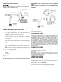
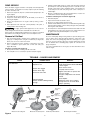
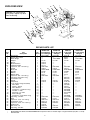
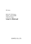
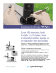
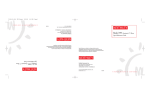
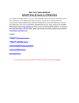
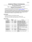
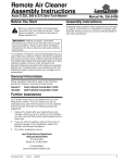
OWNER’s MANUAL “ED”, “EDD”, and “EEDD” SERIES ENGINE DRIVEN SELF-PRIMING CENTRIFUGAL PUMPS Limited Warranty STA-RITE warrants to the original consumer purchaser (“Purchaser” or “You”) of the products listed below, that they will be free from defects in material and workmanship for the Warranty Period shown below. Product Warranty Period Water Systems Products — jet pumps, small centrifugal pumps, submersible pumps and related accessories whichever occurs first: 12 months from date of original installation, or 18 months from date of manufacture Pro-Source® Composite Tanks 5 years from date of original installation Pro-Source Steel Pressure Tanks 5 years from date of original installation Pro-Source® Epoxy-Lined Tanks 3 years from date of original installation Sump/Sewage/Effluent Products 12 months from date of original installation, or 18 months from date of manufacture ® Our warranty will not apply to any product that, in our sole judgement, has been subject to negligence, misapplication, improper installation, or improper maintenance. Without limiting the foregoing, operating a three phase motor with single phase power through a phase converter will void the warranty. Note also that three phase motors must be protected by three-leg, ambient compensated, extra-quick trip overload relays of the recommended size or the warranty is void. Your only remedy, and STA-RITE’s only duty, is that STA-RITE repair or replace defective products (at STA-RITE’s choice). You must pay all labor and shipping charges associated with this warranty and must request warranty service through the installing dealer as soon as a problem is discovered. No request for service will be accepted if received after the Warranty Period has expired. This warranty is not transferable. STA-RITE SHALL NOT BE LIABLE FOR ANY CONSEQUENTIAL, INCIDENTAL, OR CONTINGENT DAMAGES WHATSOEVER. THE FOREGOING WARRANTIES ARE EXCLUSIVE AND IN LIEU OF ALL OTHER EXPRESS AND IMPLIED WARRANTIES, INCLUDING BUT NOT LIMITED TO THE IMPLIED WARRANTIES OF MERCHANTABILITY AND FITNESS FOR A PARTICULAR PURPOSE. THE FOREGOING WARRANTIES SHALL NOT EXTEND BEYOND THE DURATION EXPRESSLY PROVIDED HEREIN. Some states do not allow the exclusion or limitation of incidental or consequential damages or limitations on the duration of an implied warranty, so the above limitations or exclusions may not apply to You. This warranty gives You specific legal rights and You may also have other rights which vary from state to state. This Limited Warranty is effective June 1, 2011 and replaces all undated warranties and warranties dated before June 1, 2011. STA-RITE INDUSTRIES 293 Wright Street • Delavan, WI U.S.A. 53115 Phone: 1-888-782-7483 • Fax: 1-800-426-9446 • Web Site: sta-rite.com 293 WRIGHT STREET, DELAVAN, WI 53115 WWW.sta-rite.COM PH: 888-782-7483 © 2012 Pentair, Inc. All Rights Reserved. S91 (11/27/12) California Proposition 65 Warning This product and related accessories contain chemicals known to the State of California to cause cancer, birth defects or other reproductive harm. NOTICE: MODEL EDG-105 IS BUILT FOR USE WITH SWIMMING POOLS. MODEL EDG-105 IS SHIPPED WITH A 1-1/2” SUCTION FLANGE ASSEMBLY. Figure 1 MODEL EEDD-29 PUMP UNIT ONLY Figure 2 To mount pump to your engine, proceed as follows: 1. Loosen clamp assembly (Key No. 4C) on shaft extension. Position pump adapter on motor; insert engine shaft into shaft extension. BE SURE pump adapter pilot fits pilot bore in engine. 2.Attach pump adapter to engine using (4) 5/16 x 3/4” capscrews and lockwashers–(5/16-24 capscrews are required for engines with aluminum blocks, and 5/16-18 capscrews are required for engines with cast iron blocks). 3. Push shaft extension toward pump until fibre spacer will not rotate freely on shaft. Tighten clamp assembly on shaft extension. Hold the shaft extension with a screwdriver in one of the slots while tightening the nut. 4. As the fibre spacer is used to establish impeller clearance only, it will burn out shortly after pump is put into operation and need not be replaced. NOTICE: If engine is removed, a new fibre washer should be obtained to re-establish clearance before replacing engine. 5. Use one of the following engines: (a) Briggs and Stratton (b) Kohler (c) Tecumseh Refer to engine manufacturer’s service manual for parts or service to engine. BE SURE to fill crankcase with recommended grade of oil. Do NOT run pump until it has been primed, as this could ruin the seal. * These parts are not furnished. Order Strainer Fittings Package C298-9, which includes these parts. Placing The Pump This pump is portable, and should be placed on a level foundation or firm level ground as near the water source as possible, for efficient operation. Model EEDD-29 can be mounted on an available gasoline engine. It must have the engine supported to the same level as the pump mount, to avoid placing strain on the pump adapter or engine. All suction and discharge piping should also be supported independently near the pump, to avoid strain on the unit. Standard piping can be used, or as the pump is portable, reinforced suction hose can be used on the suction inlet. This hose must have the equivalent capacity of 2” iron pipe. A strainer should be used on the end of the suction pipe or hose. See Figures 1 and 2 for typical installations. Priming The Pump Install pipe tee in the discharge opening of the pump with a nipple. Provide a priming plug in the top opening. See Figure 2. Fill the pump with water and tighten the priming plug. Start the engine, and the pump will prime, with priming time depending upon the suction lift and the horizontal distance to water. OPERATING SPEED Models With Engine These pumps leave the factory with a gas engine set to operate at 3500 rpm when pumping, which is the correct speed for maximum efficiency. Model EEDD-29 must be provided with an engine which will operate at approximately the same speed (3500 rpm). Always start the unit at full speed until unit is primed and pumping water. It can be throttled to lower the pump’s capacity while pumping. 2 Pump Service 3. Lubricate outside rubber surface of ceramic seat with soapy water and press firmly into seal cavity with finger pressure. If seat will not locate properly in this manner, place cardboard washer over polished face of seat and press into seal cavity using a 3/4” socket or 3/4” piece of standard pipe. 4. Dispose of cardboard washer. Be sure polished surface of seat is free of dirt and has not been damaged by insertion. Installation of Rotating Part of Seal Unit (Figure 3D) 1. Reinstall seal plate. 2. Inspect shaft to make sure that it is clean. 3. Clean face of sealing washer with clean cloth. 4. Lubricate inside diameter and outer face of rubber drive ring with soapy water and slide assembly on motor shaft (sealing face first) until rubber drive ring hits shaft shoulder. 5. Screw impeller on shaft until impeller hub hits shaft shoulder. This will automatically locate seal in place and move the sealing washer face up against seat facing. Reinstall impeller screw (if used). Due to the simple, rugged construction of the pump, it should require little service. However, if it should be necessary to replace a part, the following procedure should be used. 1. Remove the capscrews, Key No. 8, which hold the pump body to the engine adapter. 2. The pump body can now be removed. 3. A tap on the volute diffuser, Key No. 18, will enable you to remove it, exposing the impeller. 4.Remove the impeller from the engine shaft by turning counterclockwise. 5. Seal replacement. The shaft seal consists primarily of two parts, a rotating member and a floating seat. The highly polished and lapped faces of this seal are easily damaged. Read instructions and handle the seal with care. Some models are equipped with an impeller screw, which has a left hand thread. Before unscrewing the impeller, remove the impeller screw. MAINTENANCE Removal of Old Seal Be sure to drain pump during freezing weather to prevent damage from frost. To drain, remove drain plug directly below the suction inlet of the pump; also remove the priming plug. Drain the suction pipe at a point below the frost line. All pipe exposed to freezing temperatures should also be drained. Before restarting pump, replace all connections and plugs and reprime. For service and maintenance to the engine, see the booklet which comes with the engine. 1. After unscrewing impeller, carefully remove rotating part of seal by prying up on sealing washer, using two screwdrivers (see Figure 3A, below). Use care not to scratch motor shaft. 2. Remove seal plate from motor and place on flat surface, face down. Use a screwdriver to push ceramic seat out from seal cavity (see Figure 3B, below). Installation of Floating Seat (Figure 3C) 1. Clean polished surface of floating seat with clean cloth. 2. Turn seal plate over so seal cavity is up. Clean cavity thoroughly. Trouble – Causes and Remedy Remedies Fill pump body with water Pump should operate about 3500 RPM - Check engine Clean suction screen Put pump closer to water Tighten connections or replace with new hose or pipe Use pipe compound to seal all male threads Clean impeller Submerge suction hose or piping enough so that no air enters while pump is operating Probable Cause Pump not primed Speed too low Trouble No water delivered or not enough water delivered. Suction line clogged Suction lift too high Air leak in suction line Impeller plugged Suction end not submerged deep enough 3/4" socket or pipe Shaft shoulder Cardboard washer Rubber drive ring (supplied w/seal) Polished surface Mechanical seal rotating half Mechanical seal stationary half Rubber surface Sealing face Impeller Seal Plate A-Seal removal-rotating half B-Seal removal-stationary half C-Stationary half installation Figure 3 D-Rotating half installation 685 0294 3 EXPLODED VIEW 4C 4A 4 NOTICE: The appearance of your pump’s engine may differ from the drawing. 4B 13 1 5 6 12 11 8 4 3 2 7 9 14 16 19 20 18 10 24 25 26 15 23 17 27 25 28 22 21 REPAIR PARTS LIST EEDD-29* EEDDH-29R EDDH-29R EDG-105 EDPH-29R Key Part No. 3-1/2 HPPump 3-1/2 HP Pump 2 HP Pump 3-1/2 HP Pump No. Description Used w/ or w/oEngine w/Engine w/Engine w/Engine 1 Gas Engine 1 U277-29BR U277-29R U277-10 U277-29R 2 Grease Seal - Shaft 1 — — U9-42 — 3 Water Slinger 1 — 17351-0009 C69-2 17351-0009 4 Adapter 1 C2-49 C2-14B C2-14F C2-14B 4A Spacer 1 C43-37 ——— 4B Shaft Extension 1 C10-22 ——— 4C Clamp Assembly 1 C111-1 ——— 5 Capscrew - 3/8 - 16 x 3/4” Lg. 2 U30-72SS U30-72SS U30-72SS U30-72SS 6 Gasket 1 C20-21C20-21C20-21C20-21 7Shaft Seal 1U109-106SSU109-93SS U109-106SSU109-106SS 8 Impeller 1 C5-60C5-60C5-60H C5-60 9 Diffuser 1 C1-51C1-51C1-51C1-51 10 Diffuser Ring 1 C21-2C21-2C21-2C21-2 11 Capscrew - 3/8 - 16 x 7/8” Lg. 2 U30-73SS U30-73SS — — 11 Cap Screw 3/16-16x1” Long 2 — — U30-74C U30-74C 12 Lock Washer 3/8” 2 — — U43-12C U43-12C 13 Handle 1 C54-29C54-29C54-9BC54-9B 14 Pump Body 1 C76-52 C76-52F C176-1D C176-1 • 1-1/2” Suction Flange Assembly 1 — — C203-22 — 15 Valve Plate (1) — — C61-5SS — 16 Gasket – Flange (1) — — C20-15 — 17 Valve Washer (1) — – C43-15SS — 18 Cap Screw – 1/4-20x1/2” Long (1) — — U30-50SS — • Hex Nut – 1/4-20 (1) — — U36-36SS — 19 Pipe Plug – 1/4” NPT (1) — — U78-57SST — 20 Suction Flange (1) — — C3-22 — 21 Cap Screw – 5/16-18x3/4” Long (4) — — U30-60SS U30-60SS 22 Pipe Plug - 1/4” NPT 1 U78-57SS U78-57CT U78-57SST U78-57SST 23 Base 1 C104-9C4-73 C104-9C104-9 24 Capscrew - 5/16 - 18 x 7/8” Lg. 4 U30-777C U30-777C U30-777C U30-777C 25 Lockwasher - 5/16” 8 U43-11CU43-11CU43-11CU43-11C 26 Capscrew - 5/16 - 18 x 1-3/4” Lg. 4 U30-66C U30-65C U30-665C U30-665C 27 Engine Pads 4 C43-20— C43-20C43-20 28 Nut - 5/16” - 18 4 U36-37C U36-37C U36-37C U36-37C • Pipe Plug - 3/4” NPT 1 U78-60S U78-60S — — * • Model EEDD-29 is identical to Model EEDDH-29R except that it does not include engine or engine hardware (Key Nos. 1, 23-28). Not illustrated. 4