1
2:02 PM
Page 1
GREATER
2/19/03
A
MEASURE
2UP Covers
© Copyright 2000 Keithley Instruments, Inc.
Printed in the U.S.A.
OF
595-903-01A
CONFIDENCE
04/2001
1-888-KEITHLEY (534-8453) www.keithley.com
440-248-0400 • Fax: 440-248-6168
Model 595 Quasistatic CV Meter
28775 Aurora Road • Cleveland, Ohio 44139
Keithley Instruments, Inc.
Quick Reference Guide
Specifications are subject to change without notice.
All Keithley trademarks and trade names are the property of
Keithley Instruments, Inc. All other trademarks and trade names
are the property of their respective companies.
Keithley Instruments, Inc.
28775 Aurora Road • Cleveland, Ohio 44139
440-248-0400 • Fax: 440-248-6168
1-888-KEITHLEY (534-8453) www.keithley.com
© Copyright 2000 Keithley Instruments, Inc.
Printed in the U.S.A.
04/2001
A
GREATER
MEASURE
OF
CONFIDENCE
Specifications are subject to change without notice.
All Keithley trademarks and trade names are the property of
Keithley Instruments, Inc. All other trademarks and trade names
are the property of their respective companies.
Model 595 Quasistatic CV Meter
Quick Reference Guide
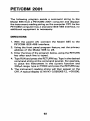
INTRODUCTION
This reference and programmingguide contains condensed
specifications, descriptions of the various features and information for using the Model 595. Also, IEEE-488programming information and several example programs written for
commonly used controllers are also included to get the
Model 595 "up and running" on the bus.
The Model 595 QuasistaticCV Meter measures capacitance
using a unique feedback charge method. This method corrects capacitance readings for background leakage current.
A built-in IEEE-488 interface, plotter driver and labeled grid
program enable the Model 595 to plot IV or quasistatic CV
curves for a variety of semiconductor materials and
components.
01986, Keithley Instruments, Inc.
Instrument Division
Cleveland, Ohio, U.S.A.
Document Number: 595-903-01 Rev. A
1
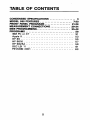
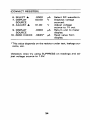
TABLE OF CONTENTS
..................
.....................
.................
CONDENSED SPECIFICATIONS
3
MODEL 595 FEATURES
7-20
FRONT PANEL PROGRAMS
21-26
MEASUREMENT CONNECTIONS............. 29-34
IEEE PROGRAMMING......................
35-49
PROGRAMS
50
IBM PC or XT . . . . . . . . . . . . . . . . . . . . . . . . . .
51
................................
Applell ...............................
HP85 ................................
HP9816 ..............................
HP9825A . . . . . . . . . . . . . . . . . . . . . . . . . . . . .
DEC El 11 ............................
PETICBM 2001 .........................
2
53
55
57
59
61
63
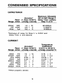
CONDENSED SPECIFICATIONS
CAPACITANCE
Maximum Allowable
Accuracy'
Wt at Half Range C
Reso- (1 b a r ) 18-28OC Delay Time=O.Oirsec
Range lution +(%rdg+counts)
Step V=O.lV
200pF lOfF
2nF lOOfF
20nF
OF
1.0
0.8
0.6
+
+
+
10
2
2
9O.OOOpA
0.900nA
9.000nA
*Exclusive of noise, for Step V 2 0.05V and
Delay Time 5 one second.
CURRENT
Temperature
Accuracy'
Coefficient
Reso- (1 Bar) 18-28OC 0-18OC & 28-4OoC
Range lution ? (%rdg+counts) f (%rdg+ counts)l°C
20pA
1fA
200pA lOfA
2nA 1OOfA
20nA
1pA
200nA lOpA
2pA 100pA
20pA
1nA
200pA lOnA
1.5
1.5
0.25
0.25
0.1
0.1
0.1
0.1
+
+
+
+
+
+
+
+
14
2
6
1
4
1
4
1
*When properly zeroed.
3
0.15
0.15
0.015
0.015
0.01
0.01
0.01
0.01
+
3
+
+
+
+
+
3
0.3
3
0.3
3
0.3
+ 0.3
+
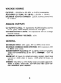
VOLTAGE SOURCE
OUTPUT: -2O.OOV to 20.00V in 0.01V increments.
ACCURACY (1 YEAR, 18-28OC): 2(0.2% + 1OmV).
MAXIMUM OUTPUT CURRENT k2mA; active current limit
at <4mA.
ANALOG OUTPUTS
C,l OUTPUT LEVEL: 1V represents 10,000 display counts
on X1 gain; 1000 display counts on X10 gain.
VOLTAGE OUTPUT LEVEL 1V represents 1OV on voltage
source output.
MAXIMUM OUTPUT VOLTAGE: k2V.
GENERAL
MAXIMUM INPUT: 30V peak, DC to 60Hz sine wave.
MAXIMUM COMMON MODE VOLTAGE 30V maximum, DC
t o 60Hz sine wave.
ENVIRONMENT: Operating: Oo to 4OoC, relative humidity
70% non-condensing up t o 35OC. Storage: -25O to
65OC.
WARM U P 2 hours to rated accuracy except input bias
current ( < 10fA after 2 hours, < 5fA after 8 hours, at
23OC)
POWER 105-125V or 210-250V (internal switch selected).
50Hz to 60Hz. 15VA max. 90-11OV and 180-220V version available upon request.
4
The following safety precautions should be observed before
using this product and any associated instrumentation Although some instruments and accessoria would normally
be used with non-hazardous voltages, there are situations
where hazardous conditions may he. present.
This product is intended for use by qualified personnel who
recognize shock hazards and are familiar with the safety
precautions required to avoid possible injury. Read and follow all installation, operation, and maintenance information
carefully before using the product. Refer to the mauual for
complete product specificatiom.
If the product is used in a manner not specified, the protection provided by the product may be impaired.
The types of product usen are:
Responsible body is the individual or group responsible for
the use and maintenance of equipment, for ensuring that the
equipmentis operated w i t h its specifcations and operating
limits,and for ensuringthat operatorsare adeqately trained.
Operators use the product for its intended function. They
must be trained in electrical safety procedures and proper use
of the instrument. They must be protected from electric
shock and contactwith hazardous live Circuits.
Maintenance personnel perform routine procedures on the
product to keep it operatingproperly, for example, setting the
line voltage or replacing collsumablematerials. Maintenance
procedms are described in the manual. The procedures explicitly state if the operator may perform them. othenvise,
they should be performed only by servicepersonnel.
Service personnel are trained to work on live circuits, and
perform safe installations and repairs of products. Only
properly trained service personnel may perform installation
and service procedws.
Keithley products are designed for use with electrical signals that are rated Installation Category I and Installation
5/02
Category II, as described in the International Electrotechnical Commission (EC) Standard IEC 60664.Most measurement, control, and data YO signals are Installation Category
I and must not be directly connected to mains voltage or to
voltage sources with high transient over-voltages. Installation Category II connections q u b t protection for high
transient over-voltagesoften associated with local AC mains
connections.Assume all measuremenfcontrol, and data YO
C O M ~ C ~ ~ O Uare
S for connection to Category I sources unless
otherwise marked or described in the Manual.
Exercise extreme caution when a shock hazard is present.
Lethal voltage may be present on cable connector jacks or
test fixtures. The American National Standards Institute
(ANSI)states that a shock hazard existswhen voltage levels
greater than 30V RMS, 42.4V peak, or 6OVDC are present.
A good safety practiceis to expect that hazardous voltage
is present in any unknown circuit before meamring.
Operators of this product must be protected from electric
shock a! all times. The responsible body must ensure that
operators are prevented access and/or insulated from every
connection point. In some cases, connections must be exposed to potential human contact. Product operators in these
circumstances must be trained to protect themselves from
the risk of electric shock. If the circuit is capable of operating at or above loo0 volts, no conductive part of the circuit maybe exposed.
Donot COMect switchingcardsdirectly to lmlialite4lpowercircuits. They are intended to be used witb impedance limited
sources. NEVER connect switching cards directly to AC
mains. When connecting soto s w i t c h cards, install
proteCrive devices to limit fault CUlTent and voltage to the card.
Before operating an instrument, make sure the line cord is
connected to a properly grounded power receptacle. Inspect
the connecting cables, test leads, and jumpers for possible
wear, cracks, or breaks before each use.
When installing equipment where access to the main power
cord is restricted,such as rack mounting, a separate main input power disconnect device must be provided, in close proximity to the equipment and within easy reach of the operator.
For maximum safety, do not touch the product, test cables,
or any other instruments while power is applied to the circuit
under test ALWAYS remove power from the enfire test system and discharge any capacitors before: connecting or disconnecting cables or jumpers, installing or removing
switching cards,or making internal changes, such as installing or removingjumpers.
Do not touch any object that couldpruvideacurrent path to the
common side of the circuit under test or power line (earth)
ground. Always make measllrements with dry hands while
standing on a dry,insulated slnface capable of withstanding the
voltage bkng measured
The instrument and accessoriesmust be used in accordance
with its specificationsand operating instructions or the safety of the equipment may he impaired.
Do not exceed the maximum signal levels of the instruments
and accessories, as defined in the specificationsand operating information,and as shown on the instrument or test fixture panels, or switching card.
When fuses are used in a product, replace with same ty-pe
and rating for continued protection against fire hazard.
Chassis connections must only be used as shield connections for measuring circuits, N(TT as safety earth ground
connections.
If you are using a test fixture,keep the lid closed while power is applied to the device under test. Safe operation requires
the use of a lid interlock.
@orb
If
ispresent,connectittosafetyearthgromd
using the wire recommended in the user documentation.
A
The
symbol on an instrument indicates that the user
should refer to the operating instructions located in the manual.
A
The
symhol on an instrument shows that it can source
or measure lo00 volts or m m , includingthe combinedeffect
of normal and common mode voltages. Use standad safety
p m t i o n s to avoid personal contact with these voltages.
The WARNING heading in a manual explains dangers that
might result in personal injury or death.Always read the associated information very carefully before performing the
indicated procedure.
The CAUTION beading in a manual explains hazards that
could damage the instrument. Such damage may invalidate
the warranty.
Instrumentation and accessories shall not be connected to
humans.
Before performing any maintenance, disconnect the line
cord and all test cables.
To maintain protection from electric shock and lire, replacement components in mains circuits, including the power
transformer, test leads, and input jacks,must be purchased
from Keithley Instruments. Standard fuses, with applicable
national safety approvals, may be used if the rating and type
are the same. Other components that are not safety related
may be purchased from other suppliers as long as they are
equivalent to the original component. (Note that selected
parts should be purchased only through Keithley Instruments to maintain accuracy and functionality of the product.) If you are unsure about the applicability of a
replacement component, call a Keithley Instruments office
for information.
To clean an instnunent, use a damp cloth or mild, water based
cleaner. Clean the exterior of the instrument only. Do not a p
ply cleaner directlyto the instrument or allow liquids to enter
or spill on the instrument. products that consist of a circuit
board with no case or chassis (e.g., data acquisition board for
installation into a computer) should never requhe cleaning if
handled according to instructions. If the board becomes contaminated and operation is affected, the board should be returned to the factory for proper cleaning/servicing.
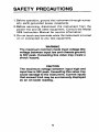
SAFETY PRECAUTIONS
1. Before operation, ground the instrument through a properly earth-grounded power receptacle.
2. Before servicing, disconnect the instrument from the
power line and all other equipment. Consult the Model
595 Instruction Manual for service information.
3. Do not touch any terminals while the instrument is turned
on or connected to any test equipment.
WARNING
The maximum common mode input voltage (the
voltage between input low and chassis ground)
is 30V peak. Exceeding this value may create a
shock hazard.
CAUTION
The maximum voltage between input high and
input low is 30V peak. Exceeding this value may
cause damage to the instrument. Current inputs
that exceed 3mA may be erroneously displayed
as an on-scale reading.
5
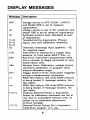
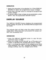
DISPLAY MESSAGES
Message Description
OFF
dc
A1
l?=S
P.=O
P.=C
OL
triG
bErr
nErr
tErr
r.r.
r.0.
[*].[*I.
[*I.[*].
Voltage source is OFF (0.OOV ?O.OlV)
and Model 595 is set to measure
capacitance.
Voltage source is set to DC waveform and
Model 595 is set to measure capacitance.
Software revision level; displayed as part
of diagnostics.
Troubleshooting diagnostics: Phases:
signal, zero and calibration reference.
Overload (overrange input applied); -0L
for negative value.
Instrument is waiting for a trigger (bus,
external, or front panel SHIFT, then ?I.
Bus Error: Instrument programmed while
not in remote; or illegal command or command option sent.
Number Error: Calibration, voltage source,
waveform parameter, or program value
beyond allowable range.
Trigger Overrun Error: Instrument triggered
during a measurement conversion.
RAM Test Failure: ON while RAM memory
is being tested. If message remains, the
test failed.
ROM Test Failure: ON while ROM memory
is being tested. If message remains, the
test failed.
Flashing Decimal Points in Exponents:
Power up calibration constants are not in
use (due to nonvolatile memory error on
power up or calibration adjustment
without storage).
Decimal Points Turned On in Exponent:
Calibration program is in use.
6
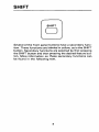
SHIFT
r
SHIFT
Several of the front panel buttons have a secondary function. These functions are labeled in yellow, as is the SHIFT
button. Secondary functions are selected by first pressing
the SHIFT button and then pressing the desired feature button. More information on these secondary functions can
be found in the following text.
7
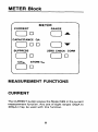
METER Block
METER
RANGE
I
SUPPRESS
I
ClCo
ZERO CHECK CORR
STORE Co
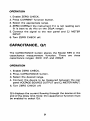
MEASUREMENT FUNCTIONS
CURRENT
The CURRENT button places the Model 595 in the current
measurement function. Any one of eight ranges (20pA to
200pA) may be used with this function.
8
OPERATION
1. Enable ZERO CHECK.
2. Press CURRENT function button.
3. Select the appropriate range.
4. ZERO CORRect the instrument if it is not reading zero
(it is best t o do this on the 20pA range).
5. Connect the signal to the rear panel and C.1 METER
INPUT.
6.Turn ZERO CHECK off.
CAPACITANCE, Q/t
The CAPACITANCE button places the Model 595 in the
capacitance measurement function. There are three
capacitance ranges: 20nF. 2nF, and 200pF.
OPERATION
1. Enable ZERO CHECK.
2. Press CAPAClTANCE button.
3. Select the desired range.
4. Connect the device to be measured between the rear
panel VOLTAGE SOURCE OUTPUT and C,I METER INPUT.
5. Turn ZERO CHECK off.
Qlt displays the current flowing through the device at the
end of the delay time. Note: the capacitance function must
be enabled to select Q/t.
9
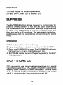
OPERATION
1. Follow steps 1-5 under capacitance.
2. Press SHIFT, then Q/t t o display Q/t.
SUPPRESS
The SUPPRESS button allows the user to compensate for
external offsets present in the test set up by subtracting
the offset value from subsequent readings. Suppress may
be used with capacitance or current measurements, but
does not apply to Q/t readings. The instrument can be toggled between Q/t and capacitance without losing the stored
value.
OPERATION
1. Select desired function and range.
2. Input the offset or baseline level to the Model 595.
3. Press the SUPPRESS button. The SUPPRESS indicator
light will turn on and the display will zero.
4. SUPPRESS can be turned off again by pressing the SUPPRESS button.
C/Co
- STORE CO
C/Co allows the user to normalize capacitance to a stored
capacitance value (C0L C/Co applies only to the capacitance
reading (even while Q/t is being displayed). Once a value
of Co is stored, it will be retained in memory until a new
value is stored or the instrument is turned off.
10
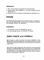
OPERATION
1. Set up the desired capacitance measurement.
2. Press SHIFT, then STORE Co. The next reading will be
stored as Co.
3. Press C/Co to normalize the capacitance readings to Co.
The Range buttons select the desired range of measurement for the Model 595. Always use the range that allows
the greatest amount of resolution.
OPERATION
1. To uprange, press the RANGE A button.
2. To downrange, press the RANGE V button.
ZERO CHECK and CORRect
Zero check is used to protect the input amplifier of the
Model 595 from overloads and switching transients when
changing instrument functions or connections to the device
under test.
Zero check is also used with zero correct to cancel internal
offsets in the Model 595. Zero correction is not applicable
to capacitance or Q/t but should be performed for the current function on the 20pA range. The zero correct value is
stored in permanent memory.
11
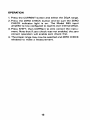
OPERATION
1. Press the CURRENT button and select the 20pA range.
2. Press the ZERO CHECK button and be sure the ZERO
CHECK indicator light is on. The Model 595 input
amplifier is now configured to read its own internal offset.
3.Press SHIFT, then CORRect to zero correct the instrument. Note that if zero check was not enabled, the zero
correct operation will enable zero check first.
4. The proper range may now be selected and ZERO CHECK
released to make a measurement.
12
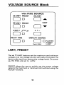
VOLTAGE SOURCE Block
f
VOLTAGE SOURCE
A L l M l T PRESET
0
ADJUST
I
r
Or
0
FAST
V L l M l T PRESET
0
0
oL-n
DELAY TIME
0
DISPLAY SOURCE
0
\
2mA M A X
0FLASHES
DURING
I-LIMIT
LIMIT, PRESET
The A, V LIMIT buttons set the maximum and minimum
voltages that the voltage source will output to protect the
device under test from destructive voltage levels. On power
up, the limits are set to k20V.
PRESET allows the user to quickly set the output voltage
value to the maximum or minimum limit without using the
ADJUST buttons.
13
OPERATION
1. Press the LIMIT A or V button to display the upper or
lower voltage limit value.
2. Use the voltage source ADJUST buttons to change either
limit in 10mV increments.
3. To quickly set the output voltage value to the maximum
or minimum limit, press SHIFT, then LIMIT PRESET A
or V.
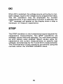
STEP V
Step V determines the step size (a small incremental change
in voltage) when either the square wave or staircase
waveform is selected. The step size may be &O.OlV,
?O.O2V, *O.OSV or kO.1OV. When plotting a curve, step
V can be set so that the curve contains the desired number
of samples (the larger the step size, the fewer number of
samples in the curve).
OPERATION
1. Press STEP V t o select the step voltage.
2. Select the step size with the ADJUST buttons.
3.To toggle the waveform between square wave and staircase, press SHIFT, then STEP V.
f, Front Panel Trigger
The ? button is used to change the polarity of the voltage
step and voltage source. This button can also be used to
trigger a single reading from the front panel.
14
OPERATION
1. Press STEP V to display the step voltage or DISPLAY
SOURCE t o display the programmed output voltage.
2.Press -c to change the polarity of the displayed value.
*
Note: Pressing SHIFT, then
will trigger a measurement
from the front panel. This is convenient if an external trigger source is unavailable.
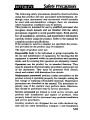
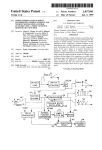
DELAY TIME
The time from the voltage step to the final charge measurement for a capacitance calculation, or from the step to the
measurement in current, is the delay time. Delay time,
0.07sec to 199.99sec. is used to allow the device under
test to respond to the change in step voltage before the
measurement. Delay time is important when performing
capacitance and CV measurements on MOS capacitors
(Delay Time must be long enough for the device to reach
equilibrium). It is not as critical when performing simple
capacitance, current, or IV measurements.
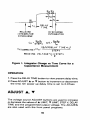
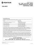
Figure 1 shows in greater detail where the delay time OCcurs. The total time of the voltage step is delay time plus
T1. IT1 is the period necessary for the Model 595 to finish
the measurement, and is typically 0.04sec.) The total time
of the voltage step (delay time plus T1 time) is called the
step time.
15
D I SCHARGE
INTEGRATOR
RELEASE
INTEGRATOR
DISCHARGE
cx
‘x(
-smv
O3-01
o h - -03-02
CORRECTED)-
to
cx‘
(O/t)(DELAY
TIHE+tl)
STEPV
READING VOLTAGE-V+ISTEPV
‘2
Figure 1. Integrator Charge vs Time Curve for a
Capacitance Measurement
OPERATION
1. Press the DELAY TIME button to view present delay time.
2. Press ADJUST A or ‘
Ibutton to increment or decrement
the time. On power up delay time is set t o 0.07sec.
ADJUST A, V
The voltage source ADJUST buttons are used to increase
ILIMIT, STEP V, DELAY
or decrease the values of A LIMIT,‘
TIME and the programmed output voltage. The ADJUSTS
are also used with the front panel programs.
16
OPERATION
1. Select the parameter to be adjusted ke., Press DISPLAY
SOURCE to select the programmed output voltage).
2. Press either ADJUST button to change the programmed
output voltage.
3. To quickly adjust these voltage source parameters, press
SHIFT, then the appropriate ADJUST button.
DISPLAY SOURCE
The DISPLAY SOURCE feature displays the programmed
output voltage. On power up, the Model 595 is programmed
for 0.OOV.
The indicator light will flash when the output current exceeds 2mA. The current limit will prevent the output current from exceeding 4mA.
OPERATION
1. Press the DISPLAY SOURCE button to view the programmed output voltage.
2. Press the voltage source ADJUST A or V button to increase or decrease the programmed output voltage.
3. Use f to change the polarity of the voltage source value
when displayed. The %Err" message will appear if a sign
change conflicts with the voltage source limits.
17
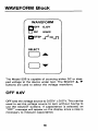
WAVEFORM
OFF 0.OV
ODC
STEP
;
i
9
0R-n
The Model 595 is capable of sourcing either DC or stepped voltage to the device under test. The SELECT A, T
buttons are used to select the voltage waveform.
OFF 0.OV
OFF sets the voltage source to 0.OOV -cO.OlV. This can be
used to set the voltage source to zero without having to
use the ADJUST buttons. If capacitance is selected, an
"OFF" message will appear on the display since a step is
necessary to measure capacitance.
18
When DC is selected, the voltage source will output a constant voltage, equal to the voltage source programmed value
The DC waveform may be employed for current
measurements. If the capacitance function is selected, the
"DC" message will appear on the display since a step is
necessary to measure capacitance.
STEP
The STEP waveform is the fundamental signal required for
capacitance measurements. Two STEP waveforms are
available: square wave and staircase The instrument powers
up with square wave enabled. Select square wave for
capacitance and current measurements at specific test
voltages, and staircase for CV,IV and Q/t-V measurements.
The characteristics of this waveform are tailored using the
controls within the VOLTAGE SOURCE block.
19
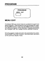
MENU EXIT
The Model 595 has several features availablethrough front
panel programs. These programs may be accessed by pressing the MENU button. Every time the MENU button is pressed a different program will be displayed. Program parameters
are changed with the voltage source ADJUST buttons.
Exit the program mode and store the parameters by pressing the SHIFT, then EXIT buttons. The instrument will return
to the previous display mode.
20
FRONT PANEL PROGRAMS
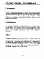
Frequency
The line frequency program is used to set the Model 595
to the available line frequency. This program is accessed
as part of the calibration procedure and does not usually
appear in the menu. Refer to Section 8 of the Model 595
Instruction Manual for detailed information about the line
frequency program.
Calibration
An advanced feature of the Model 595 is its digital calibration program. This program does not normally appear in the
menu. Refer to Section 8 of the Model 595 Instruction
Manual for detailed information about the calibration
program.
Filter
The Model 595 has three digital filters to minimize the effects of noise on individual measurements and plotted
curves. Filter 1 is used when there are 20 or more samples
in the fundamental change area of the curve, Filter 2 with
50 or more samples, and Filter 3 with slowly changing DC
signals or when there are 200 or more samples in the fundamental change area of the curve.
21
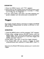
OPERATION
1. Press the MENU button until "Filt" appears.
2. Press either of the voltage source ADJUST buttons until
the desired filter number appears (0= no filter, 1 = Filter
1, 2 = Filter 2, 3 = Filter 3).
3.To exit, press SHIFT, then EXIT. The filter selected will
remain enabled until the instrument is powered off.
Trigger
The trigger program allows a stimulus to trigger the Model
595 to take a measurement on either a one-shot or continuous basis.
OPERATION
1. Press the MENU button until the message "triG" appears.
2.Press either voltage source ADJUST button until the
display reads "triG 0 to put the instrument in continuous
trigger. (When the instrument is in one-shot trigger, the
display will read "triG 1").
3.Press SHIFT, then EXIT to exit the trigger program.
4.The Model 595 will now require a trigger to begin
measurements (bus, external, or press SHIFT, then 2 ) .
Note that the Model 595 always powers up in continuous
trigger.
22
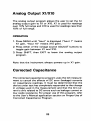
Analog Output Xl/XlO
The analog output program allows the user t o set the C.1
analog output gain to X1 or XIO. X I is used for readings
over 10%full range and XI0 is used for readings less than
10% of full range.
OPERATION
1. Press MENU until "Aout" is displayed ("Aout 1" means
X1 gain, "Aout 10' means XI0 gain).
2. Press either of the voltage source ADJUST buttons to
toggle gain between X1 and X10.
3. Press SHIFT, then EXIT to leave the analog output
program.
Note that the instrument always powers up in X I gain.
Corrected Capacitance
The corrected capacitance program uses the Q/t measurement to cancel the effects of DC error (leakage) currents
on capacitance readings. It must be determined that the
device under test has completely responded to the change
in voltage used in the measurement and that the Q/t current is only related to DC errors such as leakage current or
low oxide resistance. For proper use of this program, refer
to the User's Manual application section on Proper Use of
Corrected Capacitance Program.
23
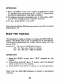
OPERATION
1. Press the MENU button until "cCAP" is displayed ("cCAP
0 signifies that correction is off, "cCAP 1" means that
corrected capacitance has been enabled).
2. To toggle corrected capacitance on or off, press either
one of the voltage source ADJUST buttons.
3. To exit, press SHIFT, then EXIT.
Note that the Model 595 always powers up with corrected
capacitance off.
IEEE-488 Address
This program is used to display or change the IEEE-488 address. The Model 595 is set to address 28 at the factory.
The following addresses (or codes) may be used with the
Model 595:
Address 0 - 30: Normal IEEE-488 address.
40 - 41: Talk only. Data to printer.
4 2 - 43: Talk only. Data to plotter.
OPERATION
1. Press the MENU button until "IEEE" appears on the
display.
2. Press either ADJUST A or V button until the desired
value is shown on the display.
3. Press SHIFT, then EXIT to return to normal operation.
Note that the IEEE-488 address is stored in permanent
memory.
24
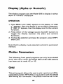
Display (Alpha or Numeric)
The display program sets the Model 595 to display in either
alpha or numeric characters.
OPERATION
1. Press MENU until "dlSP' appears on the display. (If "dlSP
U" appears, then the display is set to alpha characters.
If "dlSP - 6 appears, then the display is set to the numeric
function).
2. Press either of the voltage source ADJUST buttons to
toggle the display between the alpha and numeric
functions.
3. To store the selection and leave the program, press SHIFT,
then EXIT.
Note that the display mode selected is stored in permanent
memory.
Plotter Parameters
The following front panel programs can only be accessed
(from the menu) when the Model 595s IEEE-488 address
has been set to code 42 or 43.
Grid
The grid program allows the user to plot a grid on an HPGLcompatible plotter (HP7470A or equivalent) with the Model
595 acting as a controller. The plotter must be set to ad-
25
dress 5. The grid will be plotted according to the function,
range and limits that the Model 595 is currently set to at
the time the grid is initiated.
OPERATION
1. With the IEEE-488code set to 42 or 43, press the MENU
button until the message "Grid" appears on the display.
2. Press either of the voltage source ADJUST buttons, and
the plotter will draw and label the grid. The front panel
buttons are inoperable while the grid is being drawn.
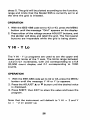
-
Y HI Y LO
The Y HI - Y Lo programs are used to set the upper and
lower plot limits of the Y axis. The limits range between
k 2 . 0 in 0.1 increments, with 2.0 corresponding to a full
20,000 count display and 0.1 corresponding to 1000
counts.
OPERATION
1 With the IEEE-488 code set to 42 or 43, press the MENU
button until the message Y HI or Y Lo appears.
2. Press the ADJUST A or V button until the desired value
is displayed.
3. Press SHIFT, then EXIT to store the value and leave the
program.
Note that the instrument will default to Y HI = 2 and Y
Lo = - 2 on power up.
26
REAR PANEL FEATURES
The following features are found on the rear panel of the
Model 595.
AC RECEPTACLE-Connects to three-wire line cord.
LINE FUSE-Provides protection on the AC power line cord.
IEEE-488-Connects the instrument to the IEEE-488 bus.
IEEE-488 interface functions are marked above the
connector.
GUARD-Provides binding post connection for shields or
the LO terminal of an external voltage source.
C.1 METER INPUT-Teflon-insulated BNC. Inner conductor
is input HI, outer conductor is GUARD.
VOLTAGE SOURCE OUTPUT-Isolated BNC connector. Inner conductor is output HI, outer conductor is GUARD.
Voltage is sourced from this output to bias devices when
making current or capacitance measurements. Referenced
to GUARD.
C.1 ANALOG OUTPUT- 5-way binding posts that correspond
to meter display (C. Qlt or I).Referenced to IEEE common.
V ANALOG OUTPUT- 5-way binding posts that correspond
to voltage at which C, Q/t or I measurement was taken.
Referenced to IEEE common.
PEN LIFT-Two 5-way binding posts; pen lift and IEEE common. Normally a TTL high output (pen up); TTL low during
a staircase waveform (pen down). Minimizes recorder pen
blotting.
27
METER COMPLETE OUTPUT-Isolated BNC connector provides negative going TTL output pulse after a reading is
completed. Referenced to IEEE common.
EXTERNAL TRIGGER INPUT-Isolated BNC connector.
Negative edge triggered, TTL level. Referenced to IEEE
common.
28
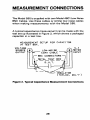
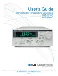
MEASUREMENT CONNECTIONS
The Model 595 is supplied with two Model 4801 Low Noise
BNC Cables. Use these cables or similar low noise cables
when making measurements with the Model 595.
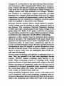
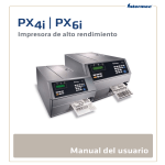
A typical capacitance measurement can be made with the
test set up illustrated in Figure 2, which shows a packaged
capacitor in a test box.
MEASUREMENT S E T U P FOR CAPACITOR
IN TEST B O X .
VOLTAGE
SOURCE
OUTPUT
Figure 2. Typical Capacitance Measurement Connections
29
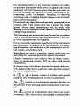
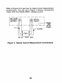
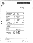
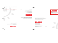
Refer to Figure 3 to see how to make current measurement
connections. The set up in Figure 3 shows connections
made with the Model 595s voltage source.
METAL TEST BOX
Figure 3. Typical Current Measurement Connections
30
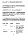
EXAMPLE MEASUREMENTS
The following examples describe typical capacitance and
current measurements. For more information about these
measurements (including CV and IV examples), refer to the
Model 595 Instruction Manual.
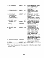
CAPACITANCE MEASUREMENT
Follow the steps outlined below to make a capacitance
measurement. The first column indicates what button
should be pressed; the second column shows what will be
displayed on the Model 595, and the last column describes
the results of the action taken.
In this example, the device under test (DUT) has a value
of about 500pF. The initial measurement configuration is
power OFF, with connections as illustrated in Figure 2. The
circuit is broken a t the capacitor under test he., the probe
is lifted from the wafer).
Button Press
Display
Remarks
r.r.
r.0.
0.000
nF
2. ZERO CHECK
0.001"
nF
3. RANGE V
.0012' nF
Memory test (RAM)
Memory test (ROM)
20nF capacitance
range, ZERO CHECK
on, square wave.
ZERO CHECK off,
measuring stray capacitance of fixture.
Go to range of
desired resolution
(DUT will be about
500pF).
1. POWER
31
4. SUPPRESS
.OOOO nF
5. ZERO CHECK
.OOOO nF
6. (Connect
capacitance
in fixture)
7. ZERO CHECK
.4562' nF
8. SHIFT, then
STORECo
.
9. CIC,
1.0000"
10. SHIFT, then
Qlt
nF
.4562' nF
.OOOO' n A
11. CAPACITANCE 1.0000*
12. CIC,
.4562' nF
SUPPRESS on, stray
value will be subtracted from all
readings.
ZERO CHECK on
while connecting
device.
Display is value of
D.U.T. (minus fixture
strays).
ZERO CHECK off t o
resume measurement.
This value is stored
as Co for normalization of capacitance.
The measured
capacitance is normalized to Co.
The magnitude of
current through the
DUT at the time of
each capacitance
measurement (i.e..
after delay time).
NOTE: Suppress and
Co apply only to the
capacitance measurement, not to Q/t.
Return to normalized
capacitance displav.
. .
C/Co off.
'This value depends on the capacitor under test, any strays
present, etc.
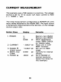
32
This example uses a 1MQresistor in a test box. The voltage
source is set to 1V to cause 1 6 input current to flow
(I = lV/MD = 1pA).
The initial measurement configuration is POWER off, with
input cables attached to the Model 595. The input circuit
is temporarily disconnectedat the test box, on the voltage
source output side.
Button Press
1. POWER
DisDlav
Remarks
r.r.
r.0.
0.000
Memory test (RAM)
Memory test (ROM)
20nF capacitance
range, ZERO CHECK
on, square wave.
Place unit in CURRENT function.
Set unit to 20pA
range.
Corrects for internal
offsets.
Go to RANGE of
desired resolution
(press five times for
this example).
nF
2. CURRENT
-.0002'nA
3. RANGE V
(press twice)
4. SHIFT, then
CORR
5. RANGE A
-0.002'pA
0.000
pA
.OOOO
pA
33
(CONNECT RESISTOR)
6. SELECT A
7. DISPLAY
SOURCE
8. ADJUST A
9. DISPLAY
SOURCE
10. ZERO CHECK
.OOOO
00.00
pA
V
01.00
V
.OOOO
FA
,9835" LA
Select DC waveform.
Displays voltage
sourced.
Adjust voltage
source to 1V out.
Return unit to meter
display.
Read value from
display.
*This value depends on the resistor under test, leakage currents. etc.
Variation: Also t r y using SUPPRESS on readings and adjust voltage source to 1.5V.
34
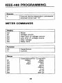
IEEE-488 PROGRAMMING
X
Execute device-dependent commands
received since last "X"
METER COMMANDS
Display
DO
I Meter
D4
D5
Voltage source
High limit of voltage source
Low limit of voltage source
Step voltage
Delay time
FO
F1
Capacitance
Current
Rl
R2
R3
R4
R5
R6
R7
R8
Capacitance(F0) Current(F1)
200pF
20pA
2nF
200pA
20nF
2nA
20nA
200nA
2 PA
2 0 pA
2 0 0 pA
35
Zero Check
I Zero check off
Zero check on
Zero check on and zero corrected
NO
N1
I
Suppress off
Suppress on using new value
Filter
Filter off
Filter 1
Filter 2
Filter 3 (DC measurements)
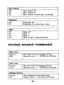
VOLTAGE SOURCE COMMANDS
I
I
I
Hiah Limit
Hnn.nn
H20
Set high limit of voltage source;
where nn.nn = -2O.OOV to 20.00V
Lnn.nn
Set low limit of voltage source;
where nn.nn = -2O.OOV to 20.00V
L-20
I Voltage Source
I Znn
Set voltage source bias level;
where nn.nn = LO limit to HI limit
36
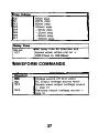
Step Voltage
so
s1
s2
s3
s4
s5
S6
s7
Delay Time
Inn.nn
I 1omv step
20mV step
50mV step
lOOmV step
-lOmV step
-2OmV step
- 50mV step
-1OOmV step
Set delay time for staircase and
square wave; where nnn.nn =
000.07sec to 199.99sec
WAVEFORM COMMANDS
I Waveform
I wo
w1
w2
w3
Voltage source off (0.0 volts)
DC output (voltage source level)
Square wave output (voltage source
+ step V)
Staircase output (voltage source +
steD V I
37
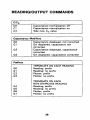
READING/OUTPUT COMMANDS
I
1 Cleo
Capacitance normalization off
Capacitance normalization on
Take new Co value
I Capacitance Modifiers
00
01
02
03
Capacitance displayed, not corrected
0 / t displayed, capacitance not
corrected
Capacitance displayed, capacitance
corrected
Q/t displayed, capacitance corrected
Preftxes
GO
G1
G2
G3
TERMINATE ON EACH READING
Reading; prefix
Reading; no prefix
Plotter; prefix
Plotter; no prefix
G4
G5
G6
G7
TERMINATE ON EACH
NON-STAIRCASE READING
Reading; prefix
Reading; no prefix
Plotter; prefix
Plotter; no prefix
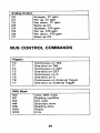
38
00
01
02
03
04
05
06
07
Autopen, X1 gain
Pen up, X1 gain
Pen down, X1 gain
Same as 0 1
Autopen, XI0 gain
Pen up, X I 0 gain
Pen down, X10 gain
Same as 0 4
BUS CONTROL COMMANDS
Triggers
TO
Tl
T2
T3
T4
T5
T6
T7
SRQ Mask
MO
M1
M2
M4
M8
M16
M32
Continuous on Talk
One-shot on Talk
Continuous on GET
One-shot on GET
Continuous on X
One-shot on X
Continuous on External Trigger
One-shot on External Trigger
I Clear SRQ mask
Reading overflow
Not used
Staircase done
Reading done
Ready
Error
I EOI and Bus Hold-off
KO
K1
K2
K3
Send EOI, hold off on X
Do not send €01, hold off on X
Send EOI, do not hold off on X
Do not send €01, do not hold off on
X
I Terminator
Y4
I
No terminator
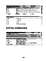
STATUS COMMANDS
1 Digital Calibration
Annn.nnE-nn
I Calibration value using exponent
Self-Test and NVRAM Storage
Perform self-test
J1-J15
No operation
Charge injection compensation
J17-Jl8
No operation
40
I Status
uo
I
u1
u2
u3
u4
u5
~
Send machine status word
Send error status word
Send data status word
Send delay time
Send high and low limits of voltage
source
Send voltage source level
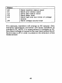
If in staircase, waveform will change t o DC (pause). Only
changing capacitance correction will cause waveform to
change to DC. NOTE: If a measurement is changed to DC,
the output voltage is moved t o the next level where the effective step is off in order to preserve the direction of the
measurement.
41
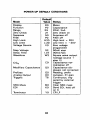
POWER UP DEFAULT CONDITIONS
Mode
Disdav
Function
Range
Zero Check
Suppress
Filter
High Limit
Low Limit
Voltage Source
3efaul
Value status
DO
FO
R3
21
NO
PO
H2 0
L-20
vo
s2
Step Voltage
Delay Time
Waveform
1.07
w2
CIC,
co
Modifiers Capacitance
QO
Prefixes
Analog Output
Triggers
GO
SRQ Mask
EOI
MO
KO
Terminator
YO
-
00
T6
42
Meter
Capacitance
20nF. 2nA
Zero check on
Suppress off
Filter off
High limit = 20V
Low limit = -2OV
Zero voltage
progammed
50mV step
000.07sec
Square wave output
(voltage source +
step V)
Capacitance normalization off
Capacitance displayed, not corrected
Reading, prefix
Autopen, X1 gain
Continuous, triggered by external
trigger
Clear SRQ mask
Send EOI, hold off
on X
CR LF
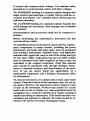
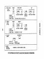
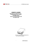
A.
CAPACIIANCE
PREFIX
OAlA
SIRING
\
0-OYERRANGE
2-ZERO CHECK
8 . CURREHI
~ 0 . 6 ~ 6 0 ~
MAHIiSJA* E X P i H E N I
‘CYI-CAPACIlAWCf.
.
-oi.m
REAbIWO
VOLIAGE
.
“f
+i.za400
MAWl’15SA
EXPONEW1
V O L I A G i . 018
II
PREFIX
OAIA
SIRING
MAWIISSA EXPOWENI
P
o-ovEnnAn6E
N-NORMAL”i,
0
2-2ERO
C.
CHECI
IVX.CURREW1.
YOLIAGE
MEASUREMEW1
PLOIlER
Fonw i
PO-Oll2b
/w
PU‘PEN up
P O - P E N OOUY
0 . G6(Fl)
ounIns
REAOIWG
vaLrmGE
A
SlAIRCASE
.
+--I
-12316
READIN6
VOLlAGE-1.126V
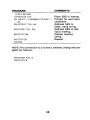
+0.69SOOE-Ii?. -12.230.+0.6~602.-12.2~0...
IF WAVEFORM IS DC OR OFF. CAPACITANCE READING IS 999999999999.
I
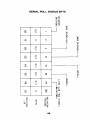
SERIAL POLL STATUS BYTE
44
MACHINE STATUS ( U O )
595FOR3ZINOCOU25200POT6GOOOOOtlOOKOYO
OEFAULT C O N D I T I O N S SHOWN
ERROR STATUS ( U I )
P
In
MOOEL NO
cPREFIXJ
IOOC
IOOCO
NO REMOTE
CONFLICT
~~~g~~~
NUM6ER
5%
In
I/O
I /o
I/o
I/o
I10
SELF-TEST
110
0 0
IATA STATUS (U2)
NO,
5%
TEMPORARY cAL
VOLTAGE SOURCE
I-LIMIT
STORAGE
ENABLED
I/o
I /o
I /o
m
I/O
z
0 0 0 0 0 <TERM>
(TERM)
IEEE-488 ADDRESS SELECTION
A front panel program is used to display and change the
IEEE-488 primary address of the Model 595. The instrument may be set to primary addresses 0 to 3 0 and IEEE-488
codes 40 to 4 3 (as long as no 0 t h instrument
~
on the bus
is set to the same value). To select an IEEE-488 address
or code, simply press the MENU button until "IEEE appears.
Then press either voltage source ADJUST button until the
desired value appears. Press SHIFT, then EXIT to store the
value.
46
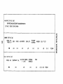
TALK ONLY OPERATION
In Talk Only operation, the instrument will control the bus
and output data t o a listening device No controller may be
on the bus. The listening device may be a listen-only printer
or an addressable printer with its address set t o 3. When
the instrument is in Talk Only, the front panel TALK indicator
light will turn on.
To place the instrument in Talk Only, perform the following
steps:
1. Using the front panel PROGRAM MENU button, display
the present IEEE-488 address value.
2. Using the voltage source ADJUST buttons, select one
of the following Talk Only parameters:
A. 40 Talk Only with prefix on data string (i.e.,
NCV1+1.23456E-12, -01.820, +1.23400E-123.
B. 41 Talk Only without prefix on data string (i.e.,
+1.23456E-12, -01.820, +1.23400E-12).
3.Press the SHIFT button and then the program EXIT button. The instrument will start talking when the measurement sequence is started.
4. Change the IEEE-488 code or go to one-shot to stop
talking.
47
IEEE-Plot
In IEEE-Plot, the instrument will output voltage and
capacitance, Q/t or current data to an IEEE-488 plotter for
the purpose of plotting the CV, IV, or Q/t-V curves of staircase measurements.
A grid can also be drawn with the labels corresponding to
the selected function, range, voltage source limit, and Y HI
- Y Lo values of the Model 595.
To use IEEE-Plot, connect an IEEE-488 plotter to the bus
connector of the Model 595 (set plotter address to 5 before
power up) and perform the following steps:
1. From the front panel, set up the Model 595 to make staircase measurements (capacitance or current). First complete the configuration of the voltage source and meter
block for the measurement. Do not start the staircase
at this time.
2. Use the program MENU button to display the present IEEE
address of the instrument.
3. Using the voltage source ADJUST buttons, set the address t o 4 2 (or to 43 to reverse the direction of the X
axis). Install plotter pen #1.
4. Press the SHIFT button and then the program EXIT
button.
5.Plot a grid as follows:
A. Press the program MENU button until the "Grid"
message is displayed.
B. To start the grid plot, press one of the voltage source
ADJUST buttons. A grid will be plotted and labels
will be placed on the X and Y axes. The labels on
the X axis correspond to the programmed high and
low voltage limits. The labels on the Y axis correspond to the Y HI and Y Lo program settings. "Y HI
= 2" corresponds to a full 20,000 count display,
while "Y HI = .1" corresponds to a 1000 count
display. Adjust Y HI and Y Lo to "crop" the plot.
6.Press the SHIFT button, then program EXIT. The measurement plot will begin when the staircase is started.
7. To pause and restart the plot, press SELECT A to pause
and SELECT V to continue.
NOTES:
1. The display can be toggled between capacitance and Q/t
while plotting without affecting the plot.
2. Changing functions, ranges, zero check or voltage source
settings will cause the staircase and plot to stop. When
the staircase is restarted, keep in mind that the labels on
the plot correspond to the original functionlrange and
voltage limits but the new plot parameters correspond
to the new Model 595 settings.
49
PROGRAMS
The following programs are designed to be a simple aid to
the user. They are not intended to suit specific needs. Each
program is designed to send a device-dependentcommand
string to the instrument and obtain and display an instrument reading string. Detailed programming information can
be found in the instruction manual.
50
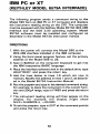
IBM PC or XT
(KEITHLEY MODEL 8573A INTERFACE)
The following program sends a command string to the
Model 5 9 5 from an IBM PC or XT computer and displays
the instrument reading string on the CRT. The computer
must be equipped with the Keithley Model 8573A IEEE-488
Interface and the DOS 2.00 operating system. Model
8573A software must be installed and configured as
described in the Model 8 5 7 3 A instruction manual.
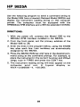
DIRECTIONS
1. With the power off, connect the Model 5 9 5 to the
IEEE-488 interface installed in the IBM computer.
2. Using the front panel program feature, set the primary
address of the Model 5 9 5 to 28.
3. Type in BASICA on the computer keyboard to get into
the IBM interpretive BASIC language.
4. Place the interface software disk in the default drive, type
LOADDECC: and press the return key.
5. Add the lines below to lines 1-6 which are now in
memory. Modify the address in lines 1 and 2, as described in the Model 8573A Instruction Manual.
6.Run the program and type in the desired command string.
For example, to place the instrument in the current function and 200pA range, type in FlR8X and press the return
key.
7. The instrument reading string will then appear on the
display. For example, the display might show
NlVX +0.59500E-4, +OO.OOO.
8. To exit the program, type in EXIT at the command prompt
and press the return key.
51
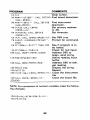
PROGRAM
19 l:Ls
29 NAB=' 'GFIEB? :CALL I E F I N D
<MA$. BEDO;;)
38 NA$=' 'DE!!~'!
:CALL IBFIND
(NAB* rw35:::l
49 [!::=28 : CALL I BPAII
( p1595:,; 7 u
:. )
59 l.!%=&H1@2 : CALL IBPOKE
<:BF:Do>;, O%:I
69 !!%=I: CALL IBSREIERDO%~V%:~
76 INFLIT' 6 1;cIpirikNn STRING?
;
COMMENTS
Clear screen.
Find board descriptor.
Find instrument
descriptor.
Set primary address
to 28.
Set timeouts.
Set REN true.
Prompt for command.
CMDS
See if program is to
be halted.
Check for null input.
'39 I F tzMIt$=' i THEN 70
Address 595 to
19M CHLL I E L J R T ( ~ I ~ , C~S
I ,: ~ % .
listen, send string.
Def.ine reading input
119 EIl$=SPACE$~: 19B:~
buffer.
Address 595 to talk,
129 CkLL IERIIiM595%rRDS:~
get reading.
Display the string.
139 P R I N T ED$
149 GijTi3 78
Repeat.
150 U%=EI: CALL IBi:ibiLrm95::r 1.P;) Close the instrument
file.
Close the board file.
1Es9C A L L IB[I~(L BF:DK:r I.I: :&
89 IF l:riD$=c
'E:XIT?
7
THEN 158
f<
179 END
NOTE: For conversion to numeric variable, make the following changes:
52
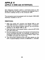
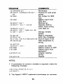
APPLE II
(APPLE II IEEE-488 INTERFACE)
The following program sends a command string to the
Model 595 from an Apple II computer and displays the instrument reading string on the computer CRI.
The computer must be equipped with the Apple I1IEEE-488
Interface installed in slot 3.
DIRE(=TIONS
1. With the power off, connect the Model 595 to the
IEEE-488 interface installed in the Apple II computer.
2. Using the front panel program feature, set the primary
address of the Model 595 to 28.
3. Enter the lines in the program below, using the RETURN
key after each line.
4. Run the program and type in the desired command string
at the command prompt. For example, to place the instrument in the current function and 200pA range, type
in FlR8X and press the return key.
5. The instrument reading string will then appear on the
CRT. A typical display is: NIVX+0.59500E-4. +OO.OOO.
53
COMMENTS
PROGRAM
16 Z$=CHRB < 2E. I
26 INPUTi COMMAND STRING?
;
Rf
38 PR#3
Terminator.
Prompt for and enter
string.
Set output to IEEE
bus.
Define input from
IEEE bus.
Remote on.
Address 595 to
listen, send string.
Line feed on.
46 I N # 3
56 PRINT’ 6 RAc‘ 3
66PRINT”WT<?‘:Zf;E9
7MPpINT’iLF1’3
86 PRINT 6 6 RIB‘ I j lCHF:$!:92)
:31 *$=ii : c*=? ?
j
R$
Strings initially
empty.
82 GET A$
Read a character.
Echo the character.
83 PRINT AS
84 I F ASC iAB>=13THEN GOTO 98 End of input if CR.
85C*=CB+A$
Add characters to
string.
86 GOTO 82
Untalk the 595.
98 P R I N T i ‘ L I T ? ?
Define output to CRT.
166 PR#B
118 I N # @
Define input from
keyboard.
1 2 6 PRINT CB
Display reading
string.
13g GOTO 28
Repeat
NOTES:
1. If conversion to numeric variable is required, make the
following changes.
1 EB C=!!kL c M IDB r: CB. 5 ? 14 :+
125 PRINT C
:,
2. The Apple II INPUT statement terminates on commas.
54
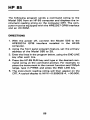
HP 85
The following program sends a command string to the
Model 595 from an HP-85 computer and displays the instrument reading string on the computer CRT. The computer must be equipped with the HP82937 GPlB Interface
and an 110 ROM.
DIRECTIONS
1. With the power off, connect the Model 595 to the
HP82937A GPlB interface installed in the HP-85
computer.
2. Using the front panel program feature, set the primary
address of the Model 595 to 28.
3. Enter the lines in the program below, using the END LINE
key after each line
4. Press the HP-85 RUN key and type in the desired command string at the command prompt. For example, to
place the instrument in the current function and 200pA
range, type in FlR8X and press the END LINE key.
5. The instrument reading string will then appear on the
CRT. A typical display is: NIVX+0.59500E-4, +OO.OOO.
55
COMMENTS
PROGRAM
lMDIM(ilC4MIrE$I:481
26 REtWTE 728
3El U I S F ‘ CnMMANDSTl?IIr(G’
48 INPUT k$
’
‘;
66 ENTER 7 2 8 ; EB
Dimension strings.
Place 595 in remote.
Prompt for command.
Input command
string.
Address 595 to
listen, send string.
Address 595 to talk,
input reading.
Display reading
string.
Repeat.
NOTE: For conversion to numeric variable, change line 70
as follows:
56
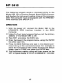
HP 9816
The following program sends a command string to the
Model 595 from a Hewlett-Packard Model 9816 computer
and displays the instrument reading string on the computer
CRT. The computer must be equipped with the HP82937
GPlB Interface and BASICA 2.0.
DIRECTIONS
1. With the power off, connect the Model 595 to the
HP82937A GPlB interface installed in the 9816
computer.
2. Using the front panel program feature, set the primary
address of the Model 595 to 28.
3. Type EDIT and press the EXEC key.
4. Enter the lines in the program below, using the ENTER
key after each line.
5. Press the 9816 RUN key and type in the desired command string at the command prompt. For example, to
place the instrument in the current function and 2 0 0 d
range, type in FlR8X and press the ENTER key.
6. The instrument reading string will then appear on the
CRT. A typical display is: NIVX+0.59500E-4, +OO.OOO.
57
PROGRAM
COMMENTS
Place 595 in remote.
Prompt for and input
command.
Address 595 to
listen, send string.
Address 595 to talk.
input reading.
Display reading
string.
Repeat.
58 P R I N T BB
NOTE: For conversionto a numeric variable, change the program as follows:
4 8 ENTER 728j B
58 P R I N T B
58
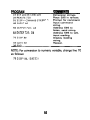
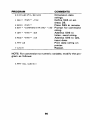
HP 9825A
Use the following program to send a command string to
the Model 595 from a Hewlett-Packard Model 9825A and
display the instrument reading string on the computer
printer. The computer must be equipped with the
HP98034A HPlB Interface and a 9872A extended I/O ROM.
DIRECTIONS:
1. With the power off, connect the Model 595 to the
98034A HPlB interface installed in the 9825A.
2. From the front panel, set the primary address of the
Model 595 to 28.
3. Enter the lines in the program below, using the STORE
key after each line. Line numbers are automatically
assigned by the 9825A.
4. Press the 9825A RUN key and type in the desired command string at the command prompt. For example, to
place the instrument in the current function and 200pA
range, type in FlR8X and press the CONT key.
5. The instrument reading string will then appear on the
computer print out. A typical display is:
NlVX +0.59500E-4,
00.000.
+
59
PROGRAM
COMMENTS
Dimension data
strings.
1 UEI..! i 595' ! ? 72s
Define 595 at address 28.
2 RE1.l i i 5.35' I
Place 5 9 5 in remote.
3 ENT 'COIIMANn S T R I N G ' F P S Prompt for command
string.
4 WET i 6 5.35' 5 I Bf
Address 595 to
listen, send string.
5 RE11 i '5.35'9
Address 595 to talk,
input data.
i. PFT A 6
Print data string on
printer.
7 i;Ti:i 3
Repeat.
0 IlIPlA6":'51.E*[E0I
NOTE: For conversion to numeric variable, modify the program as follows:
60
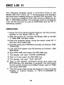
DEC LSI 11
The following program sends a command string to the
Model 595 from a DEC LSI 11 minicomputer and displays
the instrument reading string on the DEC CRT terminal. The
LSI 11 must be configured with 16K words of RAM and an
IBV 11 IEEE-488 interface. The software must be configured
with the IB software as well as FORTRAN and the RT 11
operating system.
DIRECTIONS
1. Using the front panel program feature, set the primary
address of the Model 595 to 28.
2. With the power off, connect the Model 5 9 5 to the IBV
11 IEEE-488 interface cable.
3.Enter the program below, using the editor under RT 11
and the name IEEE.FOR.
4. Compile using the FORTRAN compiler as follows: FORTRAN IEEE.
5. Link with the system and IB libraries as follows: LINK
IEEE,IBLIB.
6.Type RUN IEEE and press the RETURN key.
7.The display will read "ENTER ADDRESS'.
8.Type in 9 and press the RETURN key.
9.The display will read "TEST SETUP".
10. Type in the desired command string and press the
RETURN key. For example, to program the instrument
for the current function and 2004 range, type in FlR8X
and press RETURN.
11. The instrument data string will appear on the computer
display. A typical display is: NIVX+0.59500E-12,
+oo.ooo.
61
PROGRAM
COMMENTS
Turn off IB errors,
Allow 5 error 15s.
Allow 1 second bus
timeout.
Set line feed as
terminator.
Turn on remote.
Input primary
address.
Prompt for command
string.
Program instrument.
Address 595 to listen, send string.
Get data from instrument.
Untalk the 595.
Repeat.
62
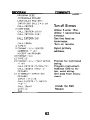
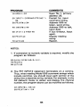
PET/CBM 2001
The following program sends a command string to the
Model 595 from a PETKBM 2001 computer and displays
the instrument reading string on the computer CRT. As the
PETKBM computer has a standard IEEE-488 interface, no
additional equipment is necessary.
DIRECTIONS
1. With the power off, connect the Model 595 to the
PETKBM IEEE-488 interface
2. Using the front panel program feature, set the primary
address of the Model 595 t o 28.
3. Enter the lines of the program below, using the RETURN
key after each line is typed.
4. Type RUN and press the RETURN key. Type in the desired
command string at the command prompt. For example,
to place the instrument in the current function and
200pA range, type in FlR8X and press the RETURN key.
5. The instrument reading string will then appear on the
CRT. A typical display is: NIVX+0.59500E-12, +OO.OOO.
63
COMMENTS
PROGRAM
10 OPEN 1328
20 INPUTL COMMAND STRING’
ES
39 P R I N T # I ? B 3
40 INPUT#I?A 3
50 I F ST = 2 THEN 40
69 PRINT A$
70 GUT0 ZB
’
j
Open file 1, primary
address 28.
Prompt for, input
command string.
Address 595 to
listen, send string.
Address 595 to talk,
input data.
If bus timeout, input
again.
Display reading
string.
Reoeat.
NOTES
1. If conversion t o numeric variable is required, modify the
program as follows:
60 A=UAL(MID3<A3:5r
78 PRINT A
SB GOT0 20
14))
2. The PET INPUT# statement terminates on a comma.
Thus, when reading Model 595 command strings which
include commas, you should input each portion of the
string into a separate string variable For example, in the
G 2 (default) mode, to obtain and display the channel
number, the program above can be modified as follows:
4 0 I N P U T # I > A33CB
E.0PRINTA3‘?’C3
64
2:02 PM
Page 1
GREATER
2/19/03
A
MEASURE
2UP Covers
© Copyright 2000 Keithley Instruments, Inc.
Printed in the U.S.A.
OF
595-903-01A
CONFIDENCE
04/2001
1-888-KEITHLEY (534-8453) www.keithley.com
440-248-0400 • Fax: 440-248-6168
Model 595 Quasistatic CV Meter
28775 Aurora Road • Cleveland, Ohio 44139
Keithley Instruments, Inc.
Quick Reference Guide
Specifications are subject to change without notice.
All Keithley trademarks and trade names are the property of
Keithley Instruments, Inc. All other trademarks and trade names
are the property of their respective companies.
Keithley Instruments, Inc.
28775 Aurora Road • Cleveland, Ohio 44139
440-248-0400 • Fax: 440-248-6168
1-888-KEITHLEY (534-8453) www.keithley.com
© Copyright 2000 Keithley Instruments, Inc.
Printed in the U.S.A.
04/2001
A
GREATER
MEASURE
OF
CONFIDENCE
Specifications are subject to change without notice.
All Keithley trademarks and trade names are the property of
Keithley Instruments, Inc. All other trademarks and trade names
are the property of their respective companies.
Model 595 Quasistatic CV Meter
Quick Reference Guide