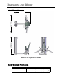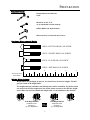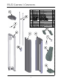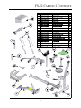
1
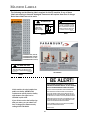
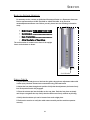
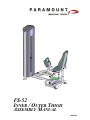
FS-52
INNER / OUTER THIGH
ASSEMBLY MANUAL
AM-FS52
A MESSAGE TO OUR CUSTOMERS
Thank you for purchasing the Paramount FS-52 Inner / Outer Thigh machine. Because of the many
unique features included in this product, this manual was created to provide you with information on
how to properly assemble and maintain your equipment. Proper maintenance will ensure that your
new equipment will last for years.
For your convenience, product questions can be answered by an Authorized Paramount Dealer or by
contacting a Paramount Customer Service Representative at:
1-800-721-2121 or 1-323-721-2121 or [email protected]
Office hours are Monday-Friday, 7:30 am - 4:30 pm PST
Paramount Fitness Corporation
6450 East Bandini Blvd.
Los Angeles, CA 90040
!
IMPORTANT
REVIEW THE GENERAL MAINTENANCE MANUAL FOR IMPORTANT SAFETY AND
MAINTENANCE TIPS. THE MANUAL HAS BEEN INCLUDED WITH YOUR MACHINE ORDER
AND CAN ALSO BE DOWNLOADED FROM OUR WEBSITE AT:
http://www.paramountfitness.com
PLEASE RETAIN THIS MANUAL FOR FUTURE REFERENCE.
2
TABLE OF CONTENTS
SAFETY......................................................................................................................
4
GENERAL CARE AND MAINTENANCE........................................................................... 5
DIMENSIONS AND WEIGHT........................................................................................... 6
PREPARATION............................................................................................................. 7
FS-52 CARTON 1 CONTENTS........................................................................................ 8
FS-52 CARTON 2 CONTENTS........................................................................................ 9
INSTALLATION & ASSEMBLY
STEP 1: ASSEMBLE THE FRAME COMPONENTS................................................. 10
STEP 2: ASSEMBLE THE ADJUSTMENT PLATE................................................... 12
STEP 3: ASSEMBLE THE LEFT ARM................................................................... 13
STEP 4: ASSEMBLE THE PADS........................................................................... 14
STEP 5: ASSEMBLE THE CONNECTING PLATE................................................... 15
STEP 6: INSTALL THE WEIGHT STACK.............................................................. 16
STEP 7A: INSTALL THE CABLES....................................................................... 17
STEP 7B: INSTALL THE CABLES........................................................................ 18
STEP 8: INSTALL THE CAM COVER................................................................... 19
STEP 9: INSTALL THE FRONT SHROUD.............................................................. 20
STEP 10: INSTALL THE REAR SHROUD.............................................................. 21
STEP 11: APPLY THE WEIGHT STACK LABEL.................................................... 22
MACHINE LABELS........................................................................................................ 23
SERVICE..................................................................................................................... 24
PARAMOUNT LIMITED WARRANTY.............................................................................. 26
3
SAFETY
1. Review and understand all of the warning labels affixed to this machine and on the facility safety
sign. Replace any warning label at first sign of wear. Labels and the Facility Safety Sign may be
obtained from Paramount free of charge.
2. Be certain that the machine operation is understood before it is used. Refer to the instruction label
provided with the machine.
3. Keep children away from this equipment. Supervise use by teenagers.
4. DO NOT high-pin or double-pin the weight stack. DO NOT allow the machine to be used if the top
plate or weight stack is pinned in a raised position. Use an assistant and carefully return the
machine to the proper position with the cap plate resting on the top weight. Inspect the cable to
ensure that it is seated in all of the pulleys.
5. Use ONLY Paramount weight selector pins. Other manufacturer’s pins may work free of the weight
stack causing possible injury. Be certain the pin is completely inserted prior to use.
6. Cables: Inspect the entire cable weekly and the end fittings daily. Pay close attention to the area
going over pulleys and to the end connections. Replace all cables at first signs of wear or on an
annual basis. Use only Paramount supplied replacement cables.
7. Nuts, Bolts, and Fasteners: Check tightness weekly. If any hardware has become loose, retighten
and/or use Loctite™ Threadlocker 242.
8. Frames and Lifting Arms: Inspect weekly for integrity and function. Replace any component at first
signs of wear.
9. Adjustment Pins: check the function of the position selector pins on the adjustable arms. Make
sure that the selector pin inserts completely into each position without binding.
10. DO NOT attempt to free any jammed assemblies by yourself as this may cause injury.
11. DO NOT use adder weights or adder weight systems on this machine.
12. Instruct Users NOT to make arm position adjustments during exercise or when pulling on the
cable end. Always support the arms when making position adjustments.
13. Instruct Users to return the handgrips and bars to their rest position before releasing. Sudden
release of the handgrips and bars may cause serious injury to users or bystanders.
14. Instruct users NOT to attach two cables to single bars or handles. Use one handle or exercise bar
for each weight stack at a time.
15. Instruct Users not to wear loose or dangling clothes or have headphone wire hanging when using
this equipment.
16. It is recommended that users receive a thorough medical exam before commencing an exercise
program. All medical issues should be reviewed to ensure that weight training will not aggravate
pre-existing medical conditions.
17. Check the function of your machine regularly by verifying the following:
•
Cables and end fittings are intact.
•
All adjustments are possible and carried out with ease.
•
The proper selector pin is in the weight stack.
•
The exercise is performed smoothly, free of noise and/or binding.
18. Follow the installation guidelines provided with the products.
19. Retain these instructions for future reference.
20. If you have any questions, do not hesitate to contact your Paramount dealer or Paramount
Fitness Corp. at (800)721-2121 or (323) 721-2121 or [email protected].
21. Refer to Maintenance Schedule label on the machine and this manual for when to perform
maintenance.
4
GENERAL CARE AND MAINTENANCE
1. Cable Ends: Inspect end fittings daily for wear. Replace cables at the first sign of wear or
on an annual basis. If the cable tension has been adjusted, be certain that the cable nut
is tight.
2. Nuts, Bolts, and Fasteners: Check tightness weekly. If any hardware has become loose,
retighten and/or use LoctiteTM brand Threadlocker 242.
3. Frames: Wipe all machines down with a damp cloth and dry completely each day. This
includes painted parts, chrome parts and upholstered pads.
4. Painted and chrome plated parts: Use Simple Green or similar cleaner for light dirt and
grime. Use Turtle Wax Polishing Compound or a good car polish to remove heavier dirt
and grease as well as for polishing. DO NOT use solvents, lacquer thinner, acetone or
finger nail polish remover. For scuffs and marks that are not removed by the above
methods use a soft scrub cleanser. Make sure all parts are dry upon completion.
5. Weight stack enclosures (shrouds): Wipe down with a damp cloth as needed.
6. Exercise instruction labels: Clean with soap and water as needed.
7. Guide rods: Wipe all dirt and dust from the guide rods before applying a light application
of Tri-FlowTM or other teflon spray lubricant. Spray the Tri-FlowTM on a rag and then wipe
the guide rods with the rag. DO NOT use oil lubricants such as WD-40. Caution: Tri-FlowTM
will stain carpet and clothing.
8. Bronze bushings: Check monthly for signs of wear and replace as needed. Lubricate
monthly with Tri-FlowTM.
9. Please refer to the General Maintenance Manual (part number: AM-GMM) for other
important safety and maintenance information.
10. Hardware and components are indicated with a balloon. Refer to the hardware tables
that accompany each step for corresponding size and type.
11. Be sure all hardware is tight before using the machine.
!
!
DO NOT install any fitness equipment near a pool, hot tub or other damp locations. Corrosion
caused by installation in these locations can lead to premature failure of components.
After you have unpacked and inventoried all of the components, read through the
remainder of the assembly instructions to familiarize yourself with the assembly
procedure!
Each step will require the components shown in the table associated with the step.
Read the instructions for each step before assembling.
5
DIMENSIONS AND WEIGHT
“IN USE” MACHINE DIMENSIONS
64.5” (164 cm)
67.0” (170 cm)
60.5” (154 cm)
Maximum user weight: 300 lbs. (136 KG)
MACHINE WEIGHT AND FLOOR LOADING
WEIGHT STACK CONFIGURATION
MACHINE WEIGHT
APPROXIMATE FLOOR LOADING
170 lbs.
455 LBS [206 KG]
66 LBS/FT2 [322 KG/M2]
250 lbs.
535 LBS 243 KG]
78 LBS/FT2 [379 KG/M2]
6
PREPARATION
REQUIRED TOOLS:
Ratchet Wrench and Sockets:
9/16”
Wrenches: 9/16”, 3/4”.
(or an adjustable crescent wrench).
Rubber Mallet and Steel Hammer
Allen wrenches: (included with the machine)
Hardware Measurement Guide:
BHCS - BUTTON HEAD CAP SCREW
SHCS - SOCKET HEAD CAP SCREW
FHCS - FLAT HEAD CAP SCREW
HHCS - HEX HEAD CAP SCREW
1
2
3
4
5
MEASURE BOLT
FROM HERE
Weight Plate Cartons:
Weight plates are packaged (4) per box. You should have (4) boxes of weights. This will
give you a total of 16 weight plates.
The weight plates are available in two different sizes, 10 lbs. and 15 lbs. The 10 lbs. plates
are used on the 170 lbs weight stack, the 15 lbs. plates are used on the 250 lbs. weight
stack. Make sure you know which size weight stack is to be installed on this machine.
10 LB. Weight Plate Box
Part Number: B1602
Comprised of
(4) x 10 lb. Weight Plates
OR
7
15 LB. Weight Plate Box
Part Number: B1603
Comprised of
(4) x 15lb. Weight Plates
FS-52 CARTON 1 CONTENTS
ITEM
1
2
6
PART NO.
DESCRIPTION
QTY.
1
FS-CAP-000X
TOP UPRIGHT CAP
1
2
FS-GRD-200X
GUIDE ROD
2
3
FS-SHD-250X
REAR SHROUD
1
4
FS52-SHD-200X
FRONT SHROUD
1
5
FS52-UPR-000X
UPRIGHT FRAME
1
6
FS-BKT-000
GUIDE ROD BRACKET
2
7
FS-WSB-000
WEIGHT STACK BASE
2
8
FS52-PAD-100X
SEAT PAD
1
9
FS-PAD-000X
BACK PAD
1
10
FS-FLT-100X
FLOATING PULLEY HOUSING
1
11
FS52-PAD-200X
THIGH PAD
2
11
5
3
4
7
10
9
8
8
FS-52 CARTON 2 CONTENTS
ITEM
13
5
6
7
PART NO.
DESCRIPTION
1
FS52-MFR-000X
MAIN FRAME
1
2
FS52-MFR-100X
MAIN FRAME REAR
1
3
FS52-ARM-000X
LEFT ARM
1
4
FS52-ARM-100X
RIGHT ARM
1
5
FS52-MFR-200X
ARM RETAINING ASSEMBLY
1
6
FS52-MFR-300X
THIGH PAD PLATES
2
7
FS52-AXL-000X
AXLE, RIGHT ARM
1
8
FS52-MFR-400X
SLEEVE, AXLE SPACER
1
9
FS52-PLT-400X
ARM CONNECT PLATE
1
10
FS52-CVR-100X
COVER, CAM
1
11
FS52-CVR-200X
SMALL COVER, CAM
1
12
FS52-AXL-100X
AXLE, LEFT ARM
1
13
FS52-HWR-000X
FS-52 HARDWARE BOX
1
14
FS52-ADJ-100X
ADJUSTMENT PLATE
1
15
FS52-ARM-200X
PULLEY ARM
1
16
FS52-CAM-000X
CAM, CABLE
1
17
FS-SBR-000X
SELECTOR BAR
1
15
17
8
11
QTY.
14
12
16
4
9
10
2
3
1
9
STEP 1: ASSEMBLE THE FRAME COMPONENTS
1. Position the main frame and upright
frame. Route the cable before assembling
the two components as shown.
2. Loosely assemble the main frame and
upright hardware.
3. Pre-assemble the right arm and axle as
shown. Tap the pins into position with a
hammer.
4. Assemble the thigh pad plate. Tap the pin
into position with a hammer.
5. Assemble the arm to the frame as shown.
6. After aligning all component edges and
surfaces, tighten ALL the hardware.
TOP VIEW
ITEM
PART NO.
DESCRIPTION
1
C 445
SCREW, 3/8”-16 X 1”
QTY.
3
2
C 450
SCREW, 3/8”-16 X 2-1/2”
2
3
C 749
LOCKWASHER, 3/8”
4
4
C 449
SCREW, 3/8”-16 X 2-1/4”
1
5
C 754C
FLAT WASHER, 3/8”
8
6
C 766A
LOCK NUT, 3/8”-16
2
7
C 955A
BOLT COVER, BASE
8
8
C 955S
BOLT COVER, SILVER
8
9
S 550
MOLDED RUBBER FEET
7
10
FS-CLR-002
COLLAR, 25.4MM
1
11
FS-PIN-100
ROLL PIN, 8mm X 35mm
1
12
FS-PIN-200
ROLL PIN, 10mm X 45mm
2
13
FS52-UPR-000X
UPRIGHT FRAME
1
14
FS52-MFR-000X
MAIN FRAME
1
15
FS52-MFR-100X
MAIN FRAME, REAR
1
16
FS52-MFR-300X
THIGH PAD PLATES
1
17
FS52-MFR-400X
SLEEVE, AXLE SPACER
1
18
FS52-ARM-100X
RIGHT ARM
1
19
FS52-AXL-000X
AXLE, RIGHT ARM
1
16
13
Make sure the thigh pads
can be rotated as shown.
PRE-ASSEMBLE
BEFORE INSERTING
INTO MAIN FRAME
15
Route the cable
before assembling
the frame.
(FS52-CBL-200X)
F)
B%
19
D
'
18
17
A$
C&
14
10
9
STEP 1: ASSEMBLE THE FRAME COMPONENTS
12
12
NOTE: MAKE SURE
THIGH PAD PLATE IS
ORIENTED AS SHOWN
BEFORE INSTALLING
RETAINING PIN.
DETAIL B
'(7$,/%
8, 6, 7, 5
DETAIL D
'(7$,/'
11
8, 2, 7, 5, 10
10
8, 1, 3, 7, 5
X3
DETAIL F
'(7$,/)
8, 2, 7, 5, 10
DETAIL A
'(7$,/$
DETAIL C
'(7$,/&
8, 4, 3, 7, 5, 10
11
STEP 2: ASSEMBLE THE ADJUSTMENT PLATE
1. Assemble the cam to the axle and
tighten the hardware. The cam can
only be assemble to the axle in one
orientation.
2. Pre-assemble the axle, the Pulley
Arm and the adjustment plate.
Make to sure orient the adjustment
plate as shown and then install the
roll pins using a hammer.
ITEM
PART NO.
DESCRIPTION
1
C 754C
FLAT WASHER, 3/8”
4
2
C 766A
LOCK NUT, 3/8”-16
4
3
C 911
SCREW, 3/8”-16 X 3/4”, BHCS
4
4
FS52-ADJ-100X
ADJUSTMENT PLATE
1
5
FS52-ARM-200X
PULLEY ARM
1
6
FS52-AXL-100X
AXLE, LEFT ARM
1
7
FS52-CAM-000X
CAM
1
8
FS-PIN-300
ROLL PIN, 10mm X 50mm
2
9
FS-STP-001
BUMPER STOP
1
3. Insert the axle into the bearing in
the main frame.
PRE-ASSEMBLE
BEFORE INSERTING
INTO MAIN
FRAME
QTY.
NOTE ORIENTATION
OF AXLE
8
3
CAM/CABLE
CONNECTION HERE
X4
4
5
6
2, 1
7
X4
STOP WILL BE
ADJUSTED LATER
9
(ASSEMBLED)
12
STEP 3: ASSEMBLE THE LEFT ARM
1. Assemble the left arm to the axle.
ITEM
PART NO.
DESCRIPTION
QTY.
2. Assemble the arm retaining assembly
and tighten the hardware.
1
FS52-ARM-000X
LEFT ARM
1
2
FS52-MFR-300X
THIGH PAD PLATES
1
3. Install the roll pin using a hammer. Make
sure the arm is able to be in the position
shown.
3
FS52-MFR-200X
ARM RETAINING ASSY
1
4
FS-PIN-100
ROLL PIN, 8mm X 35mm
1
NOTE ORIENTATION
OF THIGH PAD PLATE
5
C 754C
FLAT WASHER, 3/8”
2
6
C 749
LOCK WASHER, 3/8”
2
7
C 955A
BASE, BOLT CAP
2
8
C 955S
BOLT CAP, SILVER
2
9
C 455
SCREW, 3/8”-16 X 1”, HHCS
2
10
FS-CLR-002
COLLAR, 25.4 mm
1
4
TOP VIEW
10
2
3
Make sure the thigh pads
can be rotated as shown.
1
8, 9, 6, 7, 5
13
STEP 4: ASSEMBLE THE PADS
1. Assemble the pads and hardware as
shown.
2. Tighten ALL the hardware.
3. Note: make sure the thigh pads can
be assembled as shown. If they can
not, the thigh pad plates have been
installed incorrectly. Refer to Steps
1 and 3.
ITEM
PART NO.
DESCRIPTION
1
C 451
SCREW, 3/8”-16 X 2-3/4” HHCS
QTY.
2
C 446
SCREW, 3/8”-16 X 1-1/4” HHCS
4
3
C 452
SCREW, 3/8”-16 X 3” HHCS
2
2
4
C 749
LOCK WASHER, 3/8”
8
5
C 754C
FLAT WASHER, 3/8”
8
6
C 955A
BASE, BOLT COVER
8
7
C 955S
BOLT COVER, SILVER
8
8
FS52-PAD-100X
SEAT PAD
1
9
F252-PAD-200X
THIGH PAD
2
10
FS-PAD-000X
BACK PAD
1
7, 2, 4, 6, 5
10
7, 1, 4, 6, 5
8
NOTE ORIENTATION
OF THIGH PADS
9
7, 3, 4, 6, 5
14
STEP 5: ASSEMBLE THE CONNECTING PLATE
1. Assemble the connection arm and
hardware as shown. The arms will
have to be positioned so that the
plate can be attached
ITEM
PART NO.
DESCRIPTION
QTY.
1
FS52-PLT-400X
PLATE, ARM CONNECTION
1
2
C-766A
LOCK NUT, 3/8”-16
2
3
C 754C
WASHER, FLAT, 3/8”
2
2. Tighten the hardware.
1
2, 3
15
STEP 6: INSTALL THE WEIGHT STACK
1. Place the guide rods in the upright.
ITEM
2. Install the weight stack base, rubber
bumpers, and washers.
3. Install the weight plates.
4. Install the cap plate and attach the
cable with the selector pin as shown.
5. Install the Guide rod hubs and
tighten the hardware.
PART NO.
DESCRIPTION
QTY.
1
C 449
SCREW, 3/8”-16 X 2-1/4” HHCS
2
2
C 766A
LOCK NUT, 3/8”
2
3
C 754C
FLAT WASHER, 3/8”
4
4
FS-GRD-200X
ASSY, GUIDE ROD
2
5
FS-BMP-001
RUBBER BUMPER
2
6
FS-WSB-000
WEIGHT STACK BASE
2
7
FS-BKT-000
GUIDE ROD BRACKET
2
8
FS-SBR-000X
CAP PLATE ASSY
1
9
WHT-PLATE
WEIGHT PLATE 10# OR 15#
16
10
C 757A
FLAT WASHER, 1”
2
4
2, 3
7
1, 3
8
9
10
5
6
16
STEP 7A: INSTALL THE CABLES
1. Route the cable as shown, installing
the associated pulleys and hardware
as you go along.
2. After assembly, make sure the cable
and pulleys can move freely.
3. Tighten ALL the hardware.
ITEM
PART NO.
DESCRIPTION
QTY.
1
B 900
PULLEY, 4-1/2” DIA.
3
2
C 448
SCREW, 3/8”-16 X 1-3/4” HHCS
3
3
C 754C
FLAT WASHER
6
4
C 766A
LOCK NUT, 3/8”-16
3
5
FS52-CBL-100X
CABLE, FLOATING PULLEY
1
6
FS52-CBL-200X
CABLE, MAIN
1
7
FS52-PLY-000
FLOATING PULLEY HOUSING
1
8
FS-SPN-000X
SELECTOR PIN
1
9
C 750
WASHER, LOCK, 1/2”
1
2, 3
4, 3
M AX
1” (25mm)
8
1
6
INSTALL SELECTOR
PIN RING AROUND
CABLE BOLT
AS SHOWN
7
FULLY TIGHTEN
CABLE BOLT
9
5
2, 3
1
4, 3
'(7$,/$
1
1” MAX
(25mm)
4, 3
2, 3
'(7$,/ %
17
STEP 7B: INSTALL THE CABLES
1. Route the cable as shown, installing
the associated pulleys and hardware
as you go along.
2. After assembly, make sure the cable
and pulleys can move freely.
ITEM
PART NO.
DESCRIPTION
QTY.
1
B 900
PULLEY, 4-1/2” DIA.
1
2
C 448
SCREW, 3/8”-16 X 1-3/4” HHCS
1
3
C 802
SCREW, M4 X 20mm PAN HD.
1
4
C 754C
FLAT WASHER, 3/8”
2
5
C 766A
LOCKNUT, 3/8”-16
1
3. Tighten ALL the hardware.
INSTALL BOLT
3 AFTER CABLE
2, 4
1
IMPORTANT!
PLACE THE SELECTOR PIN IN THE CAP PLATE. ADJUST THE ARMS TO A MIDDLE
POSITION ON THE ADJUSTMENT DISC (45 DEGREES). MOVE THE ARMS INWARD
FROM THIS POSITION.... THEN OUTWARD. WATCH THE CAP PLATE ON THE
WEIGHT STACK. NOTICE IF THERE IS A LAG BETWEEN THE INNER AND OUTER
MOVEMENTS. ADJUST THE TRAVEL STOP TO TENSION THE CABLE. THIS WILL
REMOVE THE LAG BETWEEN INNER AND OUTER MOVEMENT.
18
5, 4
STEP 8: INSTALL THE CAM COVER
1. Place the Cam Cover into place and
loosely assemble the hardware.
2.Place the Small Cam Cover into place
and loosely assemble the hardware.
3. Align the edges and then tighten ALL
the hardware.
ITEM
PART NO.
DESCRIPTION
QTY.
1
FS52-CVR-100X COVER, CAM
1
2
FS52-CVR-200X SMALL COVER, CAM
1
3
C 680A
SCREW, BUTTON HD, 1/4”-20 X 1/2”
6
4
C 749
LOCKWASHER, 3/8”
6
5
C 754C
FLAT WASHER, 3/8”
6
6
FS-STP-001
STOP, ADJUSTABLE
2
3, 4, 5 X6
1
6
Adjust foot to touch
floor if needed.
19
2
STEP 9: INSTALL THE FRONT SHROUD
1. Place the front shroud into position.
2. Align the holes and assemble the
hardware.
3. Tighten all the hardware.
ITEM
PART NO.
DESCRIPTION
1
C 445
SCREW, 3/8”-16 X 1” HHCS
4
2
C 749
LOCK WASHER
4
3
C 754C
FLAT WASHER
4
4
FS52-SHD-200X
FRONT SHROUD
1
4
1, 2, 3
X4
20
QTY.
STEP 10: INSTALL THE REAR SHROUD
1. Set the lower screws of the shroud into the ITEM PART NO.
1 C 766A
lower brackets on the upright frame.
2. Then align the holes for the brackets at
the top of the shroud.
2
DESCRIPTION
C 675D
QTY.
LOCKNUT, 3/8”-16
2
SCREW, 1/4”-20 X 1/2” BHCS
8
3
C 444
SCREW, 3/8”-16 X 3/4” HHCS
2
4
FS-SHD-250X
REAR SHROUD
1
3. Assemble all the shroud hardware and
tighten.
5
C 754C
FLAT WASHER, 3/8”
4
6
FS-CAP-000X
TOP CAP, UPRIGHT
1
4. Assemble the top cap brackets and
hardware. Then assemble to the machine.
7
FS-BKT-001
TOP CAP, BRACKET
2
2
7
6
3, 5
2
4
21
1, 5
STEP 11: APPLY THE WEIGHT STACK LABEL
1. Select the appropriate weight stack label(s) according to your order. You can install pound
labels, kilogram labels, or both.
2. If you ordered a 170 lb. weight stack, use labels:
LBL-WSE-01170 (for pounds)
LBL-WSM-01170 (for kilograms).
3. If you ordered a 250 lb. weight stack, use labels:
LBL-WSE-01250 (for pounds)
LBL-WSM-01250 (for kilograms).
4. Remove the backing from the label to expose the adhesive. Carefully locate the label on the
shroud so that it is centered between the edge and the bend. Line up the numbers with their
corresponding weight plate. Once the correct position is attained and the label is a uniform
distance from the edge, press firmly along the entire length of the label.
5. NOTE: Adhesive takes 24 hours to fully set.
INSTALL LABEL HERE
OR HERE
20
30
40
50
60
70
80
90
100
110
120
130
140
150
160
170
22
MACHINE LABELS
The following are the Warning labels required for this FS machine. If any of these
labels are missing or become damaged, Paramount will replace them free of charge.
Note: these labels are not to scale.
! WARNING
!
MAX
MAXIMUM
Height Under Nut
to Bolt Head.
MAKE SURE
locking nut is tight.
WARNING
SERIOUS INJURY CAN OCCUR
ON THIS EQUIPMENT IF THE
CABLES AND THEIR ATTACHMENT COMPONENTS ARE NOT
INSPECTED OFTEN. REPLACE
AT FIRST SIGNS OF WEAR.
1”
P/N B2051
B2141C
B2051
B2141C
LBL-WSE-01170 (170 LB)
LBL-WSE-01250 (250 LB)
LBL-WSM-01170 (77 KG)
LBL-WSM-01250 (114 KG)
LBL-WRN-0002
!
WARNING
SERIOUS INJURY CAN OCCUR ON
THIS EQUIPMENT IF THE PIN IS NOT
COMPLETELY INSERTED BEFORE USE.
P/N B2065
ASTM F1749
LBL-PR-FS52
B2065
BE ALERT!
THE FITNESS EQUIPMENT IN THIS FACILITY
PRESENTS HAZARDS WHICH, IF NOT AVOIDED,
COULD CAUSE SERIOUS INJURY OR DEATH.
If this machine is to be installed in a
public use facility, ASTM F1749
requirements specify that the facility
sign shown to the right is to be
installed in plain view.
PRIOR TO USING THE EQUIPMENT, READ THE WARNING LABELS
AND INSTRUCTION PLACARDS AFFIXED TO EACH MACHINE.
IF YOU ARE UNSURE ON HOW TO USE A MACHINE, SEEK THE
ASSISTANCE OF OUR FLOOR PERSONNEL. WE WILL BE HAPPY
TO INSTRUCT YOU ON HOW TO USE THE EQUIPMENT PROPERLY.
IMMEDIATELY REPORT ANY PIECE OF EQUIPMENT THAT IS NOT
FUCTIONING PROPERLY TO OUR FLOOR PERSONNEL SO THAT
IT MAY BE EVALUATED AND SERVICED PROMPTLY.
If you did not receive the facility sign
with your order, you can obtain one
free of charge from Paramount by
calling 1-800-721-2121.
DO NOT ATTEMPT TO USE OR FIX ANY PIECE OF EQUIPMENT
THAT IS NOT FUNCTIONING PROPERLY
ASTM F1749-96
23
SERVICE
HOW
TO
OBTAIN SERVICE
For warranty service, contact an Authorized Paramount Dealer or a Paramount Customer
Service representative at 1-800-721-2121 or 1-213-721-2121. Or by E-mail at
[email protected]. Before you call, please have the following information
ready.
• Model Number: FS-52 INNER/OUTER THIGH
• Serial Number: ________________________
• Date of Installation: ____________________
• A brief description of the problem
The serial number is located on the front of the upright
frame at the bottom as shown.
Serial Number
FINAL CHECK
1. If you haven’t already done so, lubricate the guide rods and seat adjustment tubes with
a teflon spray lubricant. Paramount recommends using TriFlowTM brand.
2. Adjust the foot plate through each position. Verify that the adjustment pin inserts freely
into each position and is fully engaged.
3. Place the selector pin into the holder on the cap plate. Push the foot plate out slowly
until it tops out against the stop. Verify that the cable moves freely, without any binding.
4. Verify that the selector pin can be inserted into each weight plate.
5. Perform the exercise to verify the cable routes smoothly and the machine operates
correctly.
24
NOTES
25
PARAMOUNT LIMITED WARRANTY
Paramount warrants to the original purchaser from a Paramount authorized dealer that Paramount
equipment or equipment from a Paramount authorized manufacturing contractor will be free from defects
in material and workmanship under normal use and service for the following periods and in the following
respects:
LIFETIME WARRANTY - Welds, Weight Plates and Guide Rods
FIVE YEAR WARRANTY - Bronze Bushings, Sealed Rotating Bearings and Pulley Wheels
ONE YEAR WARRANTY - Cables, Linear Bearings, Linear Shafts and all other components not
mentioned elsewhere in this warranty
NINETY DAY WARRANTY - Upholstery and Grips
This limited warranty DOES NOT cover and no warranty is given with respect to:
•
Products not manufactured by Paramount
•
Products which are altered without the express written consent of Paramount
•
Products purchased other than directly from Paramount or through a Paramount
Authorized Dealer.
All warranty periods begin to run from the date of delivery to the original purchaser. The
obligation of Paramount under this warranty is limited to repairing or replacing warranted defective parts,
as Paramount may elect, at Paramount's plant in Los Angeles, California, without charge to purchaser for
either parts or labor. Purchaser is responsible for all transportation and insurance costs on returned or
replaced equipment to and from Paramount's plant in Los Angeles.
ANY IMPLIED WARRANTY, INCLUDING BUT NOT LIMITED TO THE IMPLIED
WARRANTY OF FITNESS FOR A PARTICULAR PURPOSE AND THE IMPLIED WARRANTY OF
MERCHANTABILITY, IS LIMITED TO ONE YEAR DURATION FROM THE DATE OF DELIVERY
TO THE ORIGINAL PURCHASER. SOME STATES DO NOT ALLOW LIMITATIONS ON HOW
LONG AN IMPLIED WARRANTY LASTS, SO THE ABOVE LIMITATION MAY NOT APPLY TO
YOU. THE REMEDY OF REPAIR AND REPLACEMENT IS THE EXCLUSIVE AND SOLE
REMEDY OF THE PURCHASER. PARAMOUNT SHALL NOT BE LIABLE FOR ANY SPECIAL,
INCIDENTAL, CONTINGENT OR CONSEQUENTIAL DAMAGES OF ANY KIND, INCLUDING,
BUT NOT LIMITED TO, DAMAGE OF LOSS OF OTHER PROPERTY OR EQUIPMENT AND LOST
PROFITS OR REVENUE. SOME STATES DO NOT ALLOW THE EXCLUSION OR LIMITATION OF
INCIDENTAL OR CONSEQUENTIAL DAMAGES, SO THE ABOVE LIMITATION OR EXCLUSION
MAY NOT APPLY TO YOU.
No action for breach of this written limited warranty or an implied warranty shall be commenced
more than one year after the accrual of the cause of action. This written limited warranty is the complete,
final and exclusive agreement of the parties with respect to the quality or performance of the goods and any
and all warranties and representations. No modifications of this limited warranty or waiver of its terms
shall be binding on either party unless approved in writing by an authorized corporate officer of
Paramount. This limited warranty gives you specific legal rights, and you may also have other rights which
may vary from state to state. Contact Paramount Fitness Corp., 6450 E. Bandini Blvd., Los Angeles,
California 90040-3185, for a list of authorized dealers or before returning any defective equipment.
Paramount Fitness Corp. © 2005
PARAMOUNT FITNESS CORPORATION
26
Paramount Fitness Corporation
6450 E. Bandini Blvd.
Los Angeles, CA 90040-3185
Phone: 1-323-721-2121 Fax: 323-724-2000
1-800-721-2121
www.paramountfitness.com
AM-FS52-071207.fm
REV:7/12/07