1
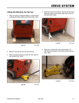
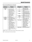
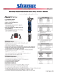
HYDRAULIC TESTING TX525 A. & B. 2-Spool Valve Hose Fitting and Coupler (Fig. 1838) Introduction Due to the many types and manufacturers of test equipment, the test hoses and fittings needed will vary. Refer to the connection information at each hydraulic test location. • Valve Hose Fitting - 13/16” - 16 ORFS 90º & 45º • Valve Hose Fitting Coupler - 13/16” - 16 x 13/16” ORFS Note: ORFS = O-ring Face Seal Test hose specifications must exceed maximum system flow and pressure and must be compatible with the type of fluid in the hydraulic system. Flow Testing The five components listed A, B, C, D and E are the primary testing locations for the TX models (Fig. 1837). F A B A. B. Pump Fitting – 1” - 14 ORFS – 90º Female (Fig. 1839) E C. D. E. F. PICT-4310a LH Hydrostat RH Hydrostat Flush face coupler Flow meter TX525 Service Manual PICT-3521a C. LH Drive Hydrostat Pump CD Fig 1837 2-Spool loader valve - 90º fitting 2-Spool loader valve - 45º fitting Fig 1838 Rev. 000 Fig 1839 DSC-0576a 9-1 HYDRAULIC TESTING D. RH Drive Hydrostat Pump Test Gauge – 3/4”-16 – 37º Female (Fig. 1842) Pump Fitting – 13/16” - 16 ORFS – Straight Female (Fig. 1840) Fig 1840 DSC-0579a Fig 1842 DSC-0577a Test hoses: E. Couplers Diameter Length PSI Rated #8 3’ (91.4cm) 5000 Coupler End – 7/8” - 14 UNF-2B O-ring Seal (Fig. 1841) E. Flow Tester (Fig. 1843) A C B Fig 1841 DSC-0580a A. Pressure gauge B. Flow gauge 9-2 Rev. 000 Fig 1843 PICT-3520a C. Restriction valve TX525 Service Manual HYDRAULIC TESTING Hydraulic Testing Hydraulic testing needs to be done in a systematic manner with a basic understanding of the hydraulic system and functions. It is recommended that you have the hydraulic schematic for the model and serial number being tested. Schematics can be obtained from this service manual or from the Toro Operator Manual or Parts Catalog provided with the unit. The TX525 hydraulic system utilizes a dual gear pump to push oil to all the hydraulic components of the unit. The TX525 hydraulic systems can be separated into three circuits: loader, auxiliary and drive. These hydraulic systems are open circuit systems that allow oil to flow when the valves and hydrostatic pumps are in neutral position. The dual gear pump draws the oil from the hydraulic tank and pushes the oil through the hydraulic lines, hoses and valves. The pump creates the flow [gallons per minute (gpm)]. The auxiliary and loader circuits are separate circuits which operate at their own pressure and flow. Return line oil from the loader circuit is used to supply oil to the two drive system hydrostatic pumps. The recommended flow (gpm) and pressure (psi) values for each of the different circuits are located in the specification section of this manual. Refer to those values to properly troubleshoot each circuit. The tests in the following section need to be done at various locations to determine which component(s) may not be functioning correctly. Loader Circut Oil is drawn from the hydraulic tank by the front section of the dual gear pump (farthest from engine) and flows into the loader valve. The loader valve relief restricts the hydraulic oil which creates system pressure (psi). When the loader valve is moved forward or back from neutral position it directs the hydraulic oil to the lift cylinder. When the loader valve is moved left and right it directs hydraulic oil to the tilt cylinder. Auxiliary Circuit Oil is drawn from the hydraulic tank by the rear section of the dual gear pump (closest to the engine) and flows into the auxiliary valve. The auxiliary valve relief restricts the hydraulic oil which creates system pressure (psi). The auxiliary valve directs the hydraulic oil to the couplers. When the auxiliary lever is moved toward the drive handle the female coupler is pressurized, which runs the attachment in forward drive. When the auxiliary lever is moved away from drive handle the male coupler is pressurized and the attachment runs in reverse drive. Drive Circuit The drive system uses two hydrostatic pumps and two wheel motors. The hydrostatic pumps are supplied with low pressure oil returned from the loader valve. This oil is filtered and then fed to the hydrostat pumps. (A 5 psi (0.34 bar) check valve on the return hose between the filter and tank is used to ensure a constant supply of oil to the hydrostatic pumps). When the drive handle is moved out of the neutral position, hydraulic oil is pumped to the wheel motors that drive the tracks. Hydrostatic Testing Procedures WARNING: Certain procedures require the vehicle engine to be operated and the vehicle to be raised off the ground. To prevent possible injury to the servicing technician and/or bystanders, ensure the vehicle is properly secured. WARNING: Do not attempt any adjustments with the engine running. Use extreme caution while working in or around all vehicle linkage! Follow all safety procedures outlined in the Operators Manual. The purpose of the flow test is to isolate and determine if there is a problem with either the hydrostatic pump or the wheel motor. CAUTION: Ensure all fittings and hoses are attached securely. This test is being completed on the vehicle’s high pressure lines. Failure to perform this test properly could result in bodily injury. TX525 Service Manual Rev. 000 9-3 HYDRAULIC TESTING Auxiliary Circuit Pressure Test 1. Cycle the hydraulic oil until warm. Note: Make sure the engine RPM is checked and set properly prior to any hydraulic testing. 2. Park the unit on level ground. This test checks the auxiliary circuit system pressure. The components involved in this test are: gear pump, auxiliary valve, auxiliary couplers and hoses. 3. Set the park brake. 4. Shut the engine off. A pressure test can be done by using a flow type or a non-flow type tester. Each tester has its own advantages and disadvantages. Flow Type Advantages of a flow type tester are that pressure and flow can be obtained with this one tester and the hydraulic load can applied slowly to compare the relativity between pressure and flow. Restrictor on flow meter can be adjusted prior to activating the hydraulic valve for pressure testing. 5. Cycle the auxiliary valve to relieve any pressure from the circuit. 6. Wipe the couplers clean. 7. Push the pressure gauge male coupler into the female coupler on the traction unit (Fig. 1844). Disadvantages of flow type tester are the expense and the hydraulic load is slowly applied so engine rpm can be overcome prior to reaching recommended system pressure. Non-Flow Type Advantages of a non-flow type tester are they are simpler, less expensive and fewer steps to obtain test results. The hydraulic load is applied quickly and system pressure can be obtained prior to engine rpm being overcome. Disadvantage of non-flow type tester is it can only be used for pressure testing. This manual will be using a flow type tester for the hydraulic testing. A non-flow tester can also be used to obtain hydraulic pressure readings. Fig 1844 PICT-3401 8. Start the engine and run at full throttle. 9. Activate the auxiliary valve handle and hold. View the pressure gauge and take a reading. 10. Specification is 3000 psi (206.8 bar). 9-4 Rev. 000 TX525 Service Manual HYDRAULIC TESTING Removal of Pressure Gauge Prior to adjusting pressure relief, flow test should be done. If adjustment of the auxiliary pressure relief valve is required, continue on. If not, skip to step 8. 1. Let the engine and hydraulic oil cool. a. Unlatch and open the rear access panel (Fig. 1846). 2. Cycle the auxiliary valve to relieve any pressure in the circuit. 3. Push back on the female coupler locking collar to sparate the fittings (Fig. 1845). Fig 1845 PICT-3402 PICT-1026 b. Using a 13mm wrench, loosen the jam nut on the auxiliary valve pressure adjustment screw (Fig. 1847). 4. Release the park brake. TX525 Service Manual Fig 1846 Rev. 000 Fig 1847 PICT-4315a 9-5 HYDRAULIC TESTING c. Using a 4mm Allen wrench, adjust the pressure adjustment screw (Fig. 1848): d. After achieving the recommended 3000 psi (206.89 bar), tighten the jam nut to lock the pressure adjustment screw in place (Fig. 1849). • Turn the screw clockwise to increase the pressure. • Turn the screw counter-clockwise to decrease the pressure. 9-6 Fig 1848 PICT-4316a Rev. 000 Fig 1849 PICT-4315a e. If pressure can not be adjusted to the recommended specification, replace or rebuild the valve or valve relief. TX525 Service Manual HYDRAULIC TESTING Auxiliary Circuit Flow Test 8. Start the engine and run at full rpm. This test checks the system flow of the auxiliary circuit. The components involved in this test are: gear pump, auxiliary valve, auxiliary couplers and hoses. When the traction unit tests to the recommendation the attachment may be at fault. 9. Activate the auxiliary valve handle and hold. View the flow (gpm) gauge, take reading. 10. Flow specification is 14 gpm (53 lpm). 11. Lower engine rpm. 12. Shut the engine off. Auxiliary Flow Testing 1. Cycle the hydraulic oil until warm. Troubleshooting 2. Park the unit on level ground. If the gpm does not meet the specification then replace the hydraulic pump. 3. Set the park brake. 4. Shut the engine off. 5. Cycle the auxiliary valve to relieve any pressure from the circuit. 6. Wipe the couplers clean. Fig 1850 1. Let the engine and hydraulic oil cool. 2. Cycle the auxiliary valve to relieve any pressure in the circuit. 7. Plug the flow meter couplers into the TX couplers (Fig. 1850). Flow Meter Removal 3. Push back on the female coupler locking collars to separate fittings (Fig. 1851). PICT-3400a Fig 1851 PICT-3400a 4. Release the park brake. TX525 Service Manual Rev. 000 9-7 HYDRAULIC TESTING Loader Circuit Flow Testing This test determines the flow output of the gear pump. The components involved in this test are: hydraulic line and pump. If the gear pump flow test meets specifications, then the loader valve or hydraulic line may be at fault. 8. Thread a flow meter hydraulic hose to the hydraulic pump fitting and tighten with a 15/16” wrench (Fig. 1853). 1. Cycle the hydraulic oil until warm. 2. Park the unit on level ground. 3. Set the park brake. 4. Cycle the loader valve to relieve any pressure from the circuit. Note: One hydraulic fitting adaptor needs to be purchased at a local hydraulic supplier. (Parker part number 8HLO = 13/16-16 ORFS x 13/16-16 ORFS) Fig 1853 PICT-3404 5. Remove the rear access panel. 7. Using a 15/16” wrench, disconnect the hydraulic hose from the pump fitting (Fig. 1852). 9. Thread the adaptor fitting to the other flow meter hydraulic hose. Tighten using a 15/16” wrench on the lfow meter hose and a 7/8” wrench on the adaptor fitting (Fig. 1854). 6. Place absorbent towels(s) below hydraulic pump. 9-8 Fig 1852 PICT-3403 Rev. 000 Fig 1854 PICT-3405 TX525 Service Manual HYDRAULIC TESTING 10. Thread the hydraulic pump hose previously removed from the pump fitting onto the adaptor on the flow meter hose. Tighten the hose using a 15/16” wrench and 7/8” wrench on the adaptor fitting (Fig. 1855). 12. Start the engine and run at full rpm. 13. Take the flow reading from the gauge (Fig. 1857). Fig 1855 Fig 1857 PICT-3408 PICT-3406 11. Using a 7/8” wrench, tighten both hoses to the flow gauge (Fig. 1856). 14. With no restriction, the flow specification is 5.5 gpm (20.8 lpm). 15. Slowly turn the restrictor on the flow meter to simulate a hydraulic load on the circuit. Note: Watch the flow gpm as the load increases (psi increases), the engine rpm and gpm should slowly decrease as load increases (psi increases). If a sudden drop in flow results, the pump should be replaced. Do not increase the load (psi) beyond 2400 + 50 psi (165 + 3.4 bar). 16. Slowly turn restrictor out until the psi on the gauge reads zero. Shut the engine off. TX525 Service Manual Fig 1856 PICT-3407 Rev. 000 9-9 HYDRAULIC TESTING Flow Gauge Removal 1. Let the engine and hydraulic oil cool prior to loosen ing any hydraulic fittings. 5. Using a 1516” wrench on the hose and a 7/8” wrench on the adaptor, remove the adaptor from the flow meter hose (Fig. 1859). 2. Cycle the loader valve handle to relieve any pres sure in the system. 3. Place an oil drain pan under the flow meter hydraulic connections. 4. Disconnect the hydraulic pump hose from the adaptor fitting using a 7/8” wrench on the adaptor fitting and a 15/16” wrench on the pump hose (Fig. 1858). Fig 1859 PICT-3405 6. Using a 15/16” wrench, disconnect the flow meter hose from the hydraulic pump (Fig. 1860). Fig 1858 PICT-3406 9-10 Rev. 000 Fig 1860 PICT-3404 TX525 Service Manual HYDRAULIC TESTING 7. Using a 15/16” wrench, connect the hydraulic hose to the hydraulic pump (Fig. 1861). Fig 1861 PICT-3403 8. Start the engine and cycle the loader valve. Inspect for leaks. 9. Release the park brake. 10. Properly discard all oily towels. TX525 Service Manual Rev. 000 9-11 HYDRAULIC TESTING Loader Circuit Pressure Test Pressure Test This test determines if the loader valve relief is properly set or working correctly. The components involved in this test are: gear pump, hydraulic lines, loader valve and test port fitting. If the pressure can not be adjusted to meet specification then the loader valve or relief valve will need to be repaired or replaced. If the pressure meets specification the loader valve is not the problem. The lift or tilt cylinder could be at fault. 1. Listed below are the Parker Hydraulics part numbers to make the test port for hydraulic pressure testing (Fig. 1862). C System flow test should be completed to assure proper flow from the pump is obtained. B 1. Cycle the hydraulic oil until warm. 2. Park the unit on level ground. 3. Set the park brake. 4. Cycle the loader valve to relieve any pressure from the circuit. Note: There is no hydraulic test port for the drive or loader circuits. Test port fittings need to be purchased at a local hydraulic supplier. A Fig 1862 PICT-3409c A. 8R6LO-S Tee fitting o-ring faced B. 8-6TRLON-S Adaptor C. PD36BTL Fitting Pressure Tester (Fig. 1863): 9-12 Rev. 000 Fig 1863 PICT-3523a TX525 Service Manual HYDRAULIC TESTING 2. Remove the rear access panel. 3. Place absorbent towel(s) below the hydraulic pump. 6. Thread the hydraulic hose (previously removed) onto the test port fitting and tighten using a 15/16” wrench (Fig. 1866). 4. Using a 15/16” wrench, remove the hydraulic hose from the pump fitting (Fig. 1864). Fig 1864 Fig 1866 PICT-3411 PICT-3403 7. Plug the test gauge into the test port (Fig. 1867). 5. Thread the test port fitting onto the hydraulic pump and tighten using a 15/16” wrench (Fig. 1865). TX525 Service Manual Fig 1865 Fig 1867 PICT-3412 PICT-3410 Rev. 000 9-13 HYDRAULIC TESTING 8. Start the engine and run at full rpm. 9. Move the loader arm handle so the tilt cylinder is retracted into the cylinder barrel. Hold the handle and take the pressure (psi) reading from the gauge (Fig. 1868). If adjustment is needed: a. Remove the RH control panel cover. b. Using a 19mm wrench and a 5mm Allen wrench, adjust the pressure adjustment screw (Fig. 1869 and Fig. 1870): • Turn the screw clockwise to increase the pressure • Turn the screw counter-clockwise to decrease the pressure. Fig 1868 PICT-3413 10. Recommended specification is 2400 + 50 psi (165 + 3.4 bar). 11. Release the handle on the loader valve and shut engine off. 9-14 Fig 1869 PICT-4326 Fig 1870 PICT-4327 Rev. 000 TX525 Service Manual HYDRAULIC TESTING c. If the recommended pressure specification can not be reached, replace or rebuild the valve. d. Install the RH control panel cover. 12. Check hydraulic fluid and add as needed. 13. Start unit and check for leaks. 14. Release park brake. 15. Shut engine off. TX525 Service Manual Rev. 000 9-15 HYDRAULIC TESTING Test Gauge Removal 5. Using a 15/16” wrench, remove the test port fitting from the hydraulic pump (Fig. 1873). 1. Let the engine and hydraulic oil cool prior to loosening any hydraulic fittings. 2. Cycle the loader valve handle to relieve any pressure in the system. 3. Using a 15/16” wrench, disconnect the test gauge from the test port fitting (Fig. 1871). Fig 1873 PICT-3410 6. Connect the hydraulic hose to the hydraulic pump and tighten with a 15/16” wrench (Fig. 1874). Fig 1871 PICT-3412 4. Using a 15/16” wrench, loosen and remove the hydraulic hose from the test port (Fig. 1872). Fig 1874 PICT-3403 7. Start the engine, cycle the loader valve and inspect for leaks. 8. Release the park brake. 9-16 Fig 1872 PICT-3411 9. Properly discard all oily towels. Rev. 000 TX525 Service Manual HYDRAULIC TESTING Traction Control Tracking Adjustment, Full Forward Position 4. If the traction unit veers right, loosen the left jam nut and adjust the tracking set screw on front of the traction control (Fig. 1876). If the traction unit does not drive straight when you hold the traction control against the reference bar, complete the following procedure: Note: Whenever an adjustment is made, check to make sure the set screws contact stops in the full forward position. C 1. Drive the traction unit with the traction control against the reference bar, noting in which direction the traction unit veers. B 2. Release the traction control. Note: When the traction control is stroked fully forward and the unit has severe pull to the left or right, a problem with the pump control linkage or a hydraulic component is indicated. Note: When the traction control is stroked fully and a gradual pull happens, the tracking adjustment can be made. A very slight tracking error is considered normal. 3. If the traction unit veers left, loosen the right jam nut and adjust the tracking set screw on the rear of traction control (Fig. 1875). A A. Left jam nut C. Reference bar Fig 1876 fig. 38a B. Operator handle 5. Repeat steps 1 through 4 until the traction unit drives straight in the full forward position. C B A A. Right jam nut C. Reference bar TX525 Service Manual Fig 1875 fig. 38a B. Operator handle Rev. 000 9-17 HYDRAULIC TESTING Traction Control Neutral Adjustment 5. Loosen the jam nuts on the traction rods, under the control panel (Fig. 1878). If the traction unit creeps forward or backward when the traction control is in neutral (and the unit is fully warmed up), make the neutral adjustment: A 1. Park the traction unit on a flat surface and lower the loader arm. 2. Stop the engine and remove the key. B 3. Lift/support the traction unit so that both tracks are off of the ground. Refer to “Lifting Unit for Service” on page 7-1. 4. Open the rear access cover (Fig. 1877). Note: Slight creeping of tracks in the forward or reverse drive with tracks off the ground can be a normal condition. Fig 1878 A. Traction rods fig. 37a B. Jam nuts 6. Start the traction unit and set the engine throttle to 1/3 engine throttle speed. 7. If the left track moves, lengthen or shorten the right traction rod until the track stops moving. 8. If the right track moves, lengthen or shorten the left traction rod until the track stops moving. 9. Tighten the jam nuts. 10. Close the rear access cover. Fig 1877 PICT-1026 11. Stop the engine and lower the traction unit to the ground. 12. Test for proper operation. 9-18 Rev. 000 TX525 Service Manual HYDRAULIC TESTING Purging Air Procedure Due to the effects air has on efficiency in hydrostatic drive applications, it is critical that air is purged from the system. These purge procedures should be implemented anytime a hydrostatic system or hydraulic line has been opened to facilitate maintenance or any additional oil has been added to the system. Air creates inefficiency because it has compression and expansion rates that are higher than that of oil. Trapped air in the oil may cause the following symptoms: 1. Noisy operation. 2. Lack of power or drive after short-term operation. 3. High oil temperature and excessive expansion of oil. Before starting, make sure the reservoir is at the proper oil level. If it is not, fill to the vehicle specifications, refer to the “Hydraulic Reservoir Tank, Checking the Hydraulic Fluid” section on page 3-4. The following procedures should be performed with the vehicle drive tracks off the ground, and then repeated under normal operating conditions. 1. Lift/support the unit so that both tracks are off the ground and free to rotate. Refer to “Lifting Unit for Service” on page 7-1. 2. Start the engine and run it at slow idle engine speed for about 20 seconds. 3. Push the traction control to the full forward position and hold. The tracks should begin to slowly rotate. Once the tracks begin to rotate smoothly, run for 20 more seconds. Pull the traction control to the full reverse position and hold. Again, the tracks should begin to slowly rotate in reverse. Once the tracks begin to rotate smoothly, allow to run for 30 more seconds. 4. Raise and lower the loader arm 4 complete cycles. Raise the loader arm and put it into the float position. The loader arm should drop. 5. Cycle the dump cylinder 4 complete cycles. 6. Stop the engine and check the oil level in the reservoir. Add as necessary. 7. It may be necessary to repeat steps 2 through 6 until all the air is completely purged from the system. TX525 Service Manual Rev. 000 9-19 HYDRAULIC TESTING THIS PAGE INTENTIONALLY LEFT BLANK. 9-20 Rev. 000 TX525 Service Manual TX525 Service Manual Form No. 492-9195