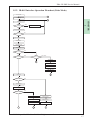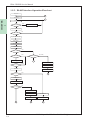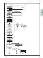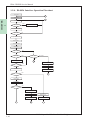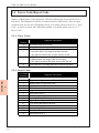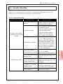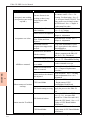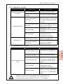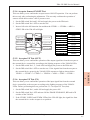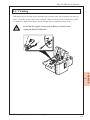
1
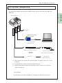
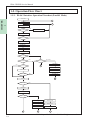
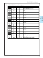
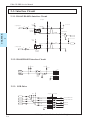
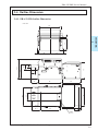
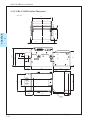
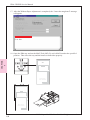
EBA-2X-PBX Service Manual Issue: 02/2007 Preface EBA-2X-PBX Service Manual Preface Thank you for purchasing JCM’s EBA-2X-PBX Bill Acceptor. Please be sure to read the following and any related documents thoroughly to understand the correct operation and features of this unit. Note 1. It is forbidden to copy the contents of this manual, in whole or in part, except for the user’s personal use, without the express permission of Japan Cash Machine Co., Ltd. 2. The information provided in this manual is subject to change without notice. 3. This manual has been written with care and attention to detail; however, should you find any errors or omissions, please contact Japan Cash machine Co., Ltd. and inform them of you findings. 4. Please be aware that Japan Cash Machine shall not be held liable by the user for any damages, losses or third party claims arising from any uses of this product. 5. All Company/Manufacturer names used in this manual are the registered trademarks of those companies. Precautions Host Machine Design - We take all possible measures to ensure the quality of this unit. However, performance degradation or possible short or open circuit faults could occur at the end of a - product’s life. Please ensure enough safety by the consideration of fail-safe design. Please allow sufficient space around the validator to facilitate removal of the unit or collection of bill. Mounting - Do not obstruct the acceptor’s air holes so that the unit may be cooled. - Do not use the e acceptor at the place where the temperature variation fluctuates widely. - Do not use the acceptor in direct sunlight or incandescent lighting (15-degree or less, - 3000Lx or more). Do not use/store the acceptor in a dusty area. - The acceptor is for indoor use only. Do not use the acceptor outside. - Do not use the acceptor in a place where chemical vapor is present. - When using the acceptor in a place where the air is subject to the car exhaust emission or cigarette smoke, please clean and maintain the acceptor at regular intervals. © 2006 Japan Cash Machine Co.Ltd. All rights reserved. 2 EBA-2X-PBX Service Manual Preface Wiring - When installing the EBA-2X-PBX unit or wiring the harness, be sure the power harness is unplugged from the power terminal to avoid unit damage. - When wiring the harness to EBA-2X-PBX unit, please use in the specified power - range and pin assignment. If not, it may cause unit damage. Be sure to connect the power harness properly. If not, incorrectly-input/output may occur by contact failure. - Do not give the power harness a strong pull, otherwise the power harness will break. Operation - Do not modify the EBA-2X-PBX unit. Doing so may damage the unit. High impact to the EBA-2X-PBX unit or dropping unit may damage to the unit. - Do not wipe the EBA-2X-PBX unit or the inside with thinner or organic solvent. - Do not add moisture or liquid to the EBA-2X-PBX unit. - Do not use the acceptor out of the opIssue: 03/2006eration Temperature/Humidity range. - The following bills might be not accepted by EBA-2X-PBX unit properly or cause bill jam or unit damage. a. Bills with stain, wear, wetness, tear or excessive wrinkles. b. Dog-eared bills c. Bills with incorrect cut dimensions or printing displacement d. Bills with smear of oil or foreign object Disposal - When this unit is disposed off, it should be done so according to your country’s regulations for similar types of industrial waste. © 2006 Japan Cash Machine Co.Ltd. All rights reserved. 3 Preface EBA-2X-PBX Service Manual Product Configurations EBA-2X-PBX’s product configurations are as follows. [Model] EBA - 22 - PB2 A B A. Acceptor Type [Type] ***(*) - * * * - *** C DEF G 1 (The maxmum accepting bill width is 79mm.) 2 (The maxmum accepting bill width is 85mm.) B. PB Unit Type - (none): for EBA-21 unit 2: for EBA-22 unit C: Country Code ISO 3 digits Country Code D: Bill Outlet direction Type1: Rear guide B (Vertical type) Type2: Rear guide A (Downward Type) Type3: Without rear guide (Holizontal Type) E: Faceplate Type 0: Without Faceplate F: Guide Block Type 1: No guide block (EBA-21: 78mm, EBA-22: 85mm) 2: Type 2 (EBA-21: 68mm, EBA-22: 75mm) 3: Type 3 (EBA-21: ~72mm, EBA-22: 70/80mm) 4: Type 4 (EBA-21: 60/71/78mm, EBA-22: 68/78/85mm) 5: Type 5 (EBA-21: 67/78mm, EBA-22: 75/85mm) G: Interface 0A2: ID-0A2 (Parallel/Pulse Interface) 003: ID-003 (Serial Interface) 0E3: ID-0E3 (CC-Talk Interface) 082A: ID-082A (Parallel/Pulse Interface) Package Contents EBA-2X-PBX unit’s packaging contains the items listed below. EBA-2X-PBX unit - This unit has been carefully packed, with special attention to quality. However if you find anything damaged of missing, please contact your local distributor immediately. © 2006 Japan Cash Machine Co.Ltd. All rights reserved. 4 EBA-2X-PBX Service Manual Preface RoHS Compliance The EBA-2X-PBX is a RoHS Compliant products. The following six kind of hazardous substances restricted by RoHS are NOT contained in the EBA-2X-PBX unit. Restricted Hazardous Substances - Plumbum - Mercury - Cadmium - Chromium Hexavalent - PBB - PBDE Documentation Conventions The list below describes the documentation convertions used in this manual. Icon/Mark Descriptions This icon indecates important information or procedures that must be followed for correct and risk-free unit operation. This icon indicates useful or recommended supplemental information. 1. 2…. This indicates steps in a procedure. Be sure to perform these steps in the order given. See=> This indicates related information to refer. * This indicates useful or important supplemental inforamation - All brand names and product names are trademarks or registered trademarks of their respective companies. © 2006 Japan Cash Machine Co.Ltd. All rights reserved. 5 Preface EBA-2X-PBX Service Manual Table of Contents Preface ............................................................................................................................. 2 Note .................................................................................................................................. 2 Precautions ...................................................................................................................... 2 Product Configurations ................................................................................................. 4 Package Contents ........................................................................................................... 4 RoHS Compliance .......................................................................................................... 5 Documentation Conventions ......................................................................................... 5 Chapter 1 Introduction 1-1. Main Features ....................................................................................................... 1-2 1-2. Prior to Use ........................................................................................................... 1-3 1-3. Parts Name............................................................................................................ 1-4 1-4. System Configuration .......................................................................................... 1-5 1-5. Operation Flow Chart ......................................................................................... 1-6 1-5-1. ID-0A2 Interface Operation Flowchart (Parallel Mode) ............................................. 1-6 1-5-2. ID-0A2 Interface Operation Flowchart (Pulse Mode) ................................................. 1-7 1-5-3. ID-003 Interface Operation Flowchart ......................................................................... 1-8 1-5-4. ID-0E3 Interface Operation Flowchart ......................................................................... 1-9 1-5-4. ID-082A Interface Operation Flowchart ..................................................................... 1-10 Chapter 2 Specification 2-1. Specification .......................................................................................................... 2-2 2-1-1. Basic Specifications .......................................................................................................... 2-2 2-1-2. Electrical Specifications ................................................................................................... 2-2 2-1-3. Environmental Specifications .......................................................................................... 2-2 2-1-4. Structural Specifications .................................................................................................. 2-2 2-2. Connector and Pin Assignment ........................................................................... 2-3 2-2-1. Interface Connector ......................................................................................................... 2-3 2-2-1-1. ID-0A2 Interface (Parallel Mode) Pin Assignment ......................................... 2-3 2-2-1-2. ID-0A2 Interface (Pulse Mode) Pin Assignment .............................................. 2-4 2-2-1-3. ID-003/ID-0E3 Interface Pin Assignment ......................................................... 2-5 2-2-1-4. ID-082A Interface Pin Assignment .................................................................... 2-6 2-2-2. CN4 Connector ................................................................................................................. 2-7 2-2-2-1. CN4 Connector Pin Assignment ........................................................................ 2-7 2-3. Interface Circuit ................................................................................................... 2-8 2-3-1. ID-0A2/ID-082A Interface Circuit .................................................................................. 2-8 2-3-2. ID-003/ID-0E3 Interface Circuit ..................................................................................... 2-8 2-3-3. LED Drive ......................................................................................................................... 2-8 © 2006 Japan Cash Machine Co.Ltd. All rights reserved. 6 EBA-2X-PBX Service Manual Preface 2-4. Outline Dimension................................................................................................ 2-9 2-4-1. EBA-20/21-PB Outline Dimension .................................................................................. 2-9 2-4-2. EBA-22-PB2 Outline Dimension ................................................................................... 2-10 2-5. DIP Switch Setting ............................................................................................. 2-11 2-5-1. When using ID-0A2 ........................................................................................................ 2-11 2-5-2. When using ID-003 ......................................................................................................... 2-12 2-5-3. When using ID-0E3 ........................................................................................................ 2-12 2-5-4. When using ID-082A ...................................................................................................... 2-13 Chapter 3 Installing/Removing 3-1. Installing/Removing ............................................................................................. 3-2 3-2. Wiring.................................................................................................................... 3-3 3-2-1. Recommended Parts ........................................................................................................ 3-3 3-2-2. Wiring Procedure ............................................................................................................. 3-3 3-3. Clearing Bill JAM ................................................................................................ 3-4 Chapter 4 Adjustment 4-1. Adjustment ........................................................................................................... 4-2 4-1-1. Requirements .................................................................................................................... 4-2 4-1-2. Proior to start adjustment ............................................................................................... 4-2 4-1-3. Adjustment Procedure ..................................................................................................... 4-3 Chapter 5 Trouble Shooting/Maintenance 5-1. Error Code/Reject Code ..................................................................................... 5-2 5-1-1. Error Code ........................................................................................................................ 5-2 5-1-2. Reject Code ....................................................................................................................... 5-2 5-2. Trouble Shooting ................................................................................................. 5-3 5-2-1. General Troubles .............................................................................................................. 5-3 5-2-2. Adjustment Troubles ........................................................................................................ 5-4 5-2-3. Communication Troubles ................................................................................................ 5-5 5-3. Test Mode (Diagnostics) ...................................................................................... 5-6 5-3-1. DIP Switch Setting List .................................................................................................... 5-6 5-3-2. Transport Motor Forward Rotation Test ....................................................................... 5-6 5-3-3. Transport Motor Reverse Rotation Test ........................................................................ 5-6 5-3-4. Acceptor Sensor ON/OFF Test ........................................................................................ 5-7 5-3-5. Acceptor I/F Test (OUT) .................................................................................................. 5-7 5-3-6. Acceptor I/F Test (IN) ....................................................................................................... 5-7 5-3-7. Bill Accepting Test ............................................................................................................ 5-8 5-3-8. PB Test ............................................................................................................................... 5-9 5-3-9. PB Feed Test ...................................................................................................................... 5-9 5-3-10. PB Motor Speed/PB Feed Motor Speed Test ............................................................... 5-9 5-3-11. Acceptor DIP Switch Test ............................................................................................. 5-10 © 2006 Japan Cash Machine Co.Ltd. All rights reserved. 7 Preface EBA-2X-PBX Service Manual 5-5. Maintenance Tool List ....................................................................................... 5-11 5-4. Cleaning .............................................................................................................. 5-11 5-6. Support ............................................................................................................... 5-12 Chpater 6 Replacement Procedure 6-1. Replacement of Faceplate Guide ........................................................................ 6-2 6-2. Replacement of CPU Board/Mother Head Board ............................................ 6-3 6-3. Replacement of Motor Unit/LED Board ............................................................ 6-6 6-4. Replacement of PB Board ................................................................................... 6-9 6-5. Replacement of Motor/Sensor Board/Belt ....................................................... 6-10 Chapter 7 Exploded View/Parts List 7-1. Entire Unit ............................................................................................................ 7-2 7-1-1. Entire Unit Exploded View .............................................................................................. 7-2 7-1-2. Entire Unit Parts List ....................................................................................................... 7-2 7-2. EBA-2X Acceptor Unit ........................................................................................ 7-3 7-2-1. EBA-2X Acceptor Unit Exploded View .......................................................................... 7-3 7-2-2. EBA-2X Acceptor Unit Parts List ................................................................................... 7-4 7-3. EBA-PBX Unit...................................................................................................... 7-6 7-3-1. EBA-PBX Unit Exploded View ....................................................................................... 7-6 7-3-1. EBA-PBX Unit Parts List ................................................................................................ 7-7 © 2006 Japan Cash Machine Co.Ltd. All rights reserved. 8 1 Chapter Introduction 1-1. Main Features 1-2. Prior to Use 1-3. Parts Name 1-4. System Configuration 1-5. Operation Flow Chart Issue: 05/2006 EBA-2X-PBX Service Manual 1-1. Main Features CHAPTER 1 In this section, EBA-2X-PBX unit’s main features are explained. Setting for Accepting Bills You can use the DIP Switch to make individual settings for the acceptance or rejection of specific bills. Allows Selection of the bill collection direction You can select one of three directions in which the bills will be ejected for bill collection in accordance with the conditions of the installation site. Picking Prevention Mechanism A Security device is installed to prevent any illegal action. Once a bill is fed into the unit, it cannot be pulled out. © 2006 Japan Cash Machine Co.Ltd. All rights reserved. 1-2 EBA-2X-PBX Service Manual 1-2. Prior to Use Be sure to follow these steps when creating the project for EBA-2X-PBX unit. 1 Before using EBA-2X-PBX unit, check the all required hardware is present and read all specification, wiring, and installation infromation. See => Chapter 2 Specification or Chapter 3 Installation/Operation 3. Setting Set the DIP switch depending on the connected host machine or the features of EBA2X-PBX unit you want to use. See => 2-5. DIP Switch Setting 4. Installation Install the EBA-2X-PBX unit and connect the harness with the host mashine. See=> Chpater 2 Specifications, or Chapter 3 Installation/Operation 5. Operation Supply the power to the EBA-2X-PB unit. © 2006 Japan Cash Machine Co.Ltd. All rights reserved. 1-3 CHAPTER 1. Preperation EBA-2X-PBX Service Manual 1-3. Parts Name A CHAPTER 1 B C D D E F A. PB Unit C. Acceptor Head E. Interface Connector G. CN5 Connector I. Diagnostic LED F G HI J B. EEPROM D. PB Unit Rlease Slide Switch F. Acceptor Head Release Knobs H. DIP Switch J. CN4 Connector © 2006 Japan Cash Machine Co.Ltd. All rights reserved. 1-4 EBA-2X-PBX Service Manual 1-4. System Configuration The following diagram represents the standard items can be connected to the EBA-2XPBX unit. CN4 Connector Cable #G 00053 Interface Connector 1 Faceplate *1 cable to connect with BV EDP No. G00053 Test Tool ID-003 (EDP# G 00176) PC (OS: Windows(R) 98 SE/2000) Harness ID-0A2 (EDP# 059310, Part#414-05-19) JCM Power Supply Unit Harness *2 adjustment Harness *3 (EDP# 059307, Part# VM-450) Host Machine (Game Machine etc.) *1 This connector can connector the special faceplate. For details, refer to 2-2-2. CN4 Connector. *2 Interface IFU-001 to adjust with VM-450 (EDP# 059301) *3 Communication harness needs to be prepared by custmer. Refer to 2-2. Connectors and Pin Assignment. ATTENTION! The adjustment is possible with MIB 232 Testadaptor or VM-450 with IFU-001. © 2006 Japan Cash Machine Co.Ltd. All rights reserved. 1-5 CHAPTER EBA-2X-PBX Unit EBA-2X-PBX Service Manual 1-5. Operation Flow Chart 1-5-1. ID-0A2 Interface Operation Flowchart (Parallel Mode) Power ON CHAPTER 1 C Initializing A Standby YES Accept Enable LED OFF INHIBIT NO Accept Enable LED ON Bill Insert NO YES Accept Enable LED OFF Motor FWD Bill Data Input Motor Stop Bill Validation NG OK NO (JAM) YES NO INHIBIT Bill Reject NO YES ABN Output Escrow A ABN LED ON YES Credit Output Bill Removed ACK or REJ REJ ABN LED OFF ACK Bill Feed PB Check C YES NO Bill Stacked YES Vend Output NO Feed Completed YES A ABN LED ON ABN LED ON Bill Removed Bill Removed ABN LED OFF ABN LED OFF C C © 2006 Japan Cash Machine Co.Ltd. All rights reserved. 1-6 EBA-2X-PBX Service Manual 1-5-2. ID-0A2 Interface Operation Flowchart (Pulse Mode) Power ON C Initializing A YES 1 Accept Enable LED OFF INHIBIT NO Accept Enable LED ON Bill Insert NO YES Accept Enable LED OFF Motor FWD Bill Data Input Motor Stop Bill Validation NG OK NO (JAM) YES INHIBIT Bill Reject NO YES ABN Output A ABN LED ON Bill Removed ABN LED OFF Bill Feed PB Check C YES NO Bill Stacked YES Vend Output NO Feed Completed YES A ABN LED ON ABN LED ON Bill Removed Bill Removed ABN LED OFF ABN LED OFF C C © 2006 Japan Cash Machine Co.Ltd. All rights reserved. 1-7 CHAPTER Standby EBA-2X-PBX Service Manual 1-5-3. ID-003 Interface Operation Flowchart Power ON C Initializing A CHAPTER 1 Standby YES Accept Enable LED OFF *3 INHIBIT NO Accept Enable LED ON *3 Bill Insert NO YES Accept Enable LED OFF *3 Motor FWD Bill Data Input Motor Stop Bill Validation NG OK NO (JAM) YES INHIBIT Bill Reject NO YES Credit Output A ABN LED ON ACK or REJ REJ Bill Removed ACK Bill Feed PB Check ABN LED OFF YES C NO Bill Stacked YES Vend Output NO Feed Completed YES ABN LED ON A Bill Removed Bill Removed ABN LED OFF ABN LED OFF C C © 2006 Japan Cash Machine Co.Ltd. All rights reserved. 1-8 EBA-2X-PBX Service Manual 1-5-4. ID-0E3 Interface Operation Flowchart Power ON E Initializing C YES Accept Enable LED OFF INHIBIT 1 NO LED ON Bill Insert NO YES Motor FWD Bill Data Input Motor Stop Bill Validation NG OK NO (JAM) YES INHIBIT Bill Reject NO YES Load the denomination to the “ Read buffered bill event” Remove JAM bill C E “Send bill to cash box” or “Return bill” “Return bill” received. “Send bill” received. Motor FWD Transport the bill until it is passed Back Lever. Acceptor Motor Stop Transport the bill until its end pass the PB Feed Sensor 1. PB Unit Motor Stop PB Unit Motor Rotate Cheating YES NO Load “Sent to cash box” to “Read buffered bill event” Waiting for “reset command” or Turn off the power D E Pass PB Feed Sensor 2 NO YES Retry 10 times NO YES Stacker Full Remove the bill C F D © 2006 Japan Cash Machine Co.Ltd. All rights reserved. 1-9 CHAPTER Standby EBA-2X-PBX Service Manual 1-5-4. ID-082A Interface Operation Flowchart Power ON C Initializing A CHAPTER 1 Standby YES Accept Enable LED OFF *3 INHIBIT NO Accept Enable LED ON *3 Bill Insert NO YES Accept Enable LED OFF *3 Motor FWD Bill Data Input Motor Stop Bill Validation NG OK NO (JAM) YES INHIBIT Bill Reject NO YES Credit Output A ABN LED ON ACK or REJ REJ Bill Removed ACK Bill Feed PB Check ABN LED OFF YES C NO Bill Stacked YES Vend Output NO Feed Completed YES ABN LED ON A Bill Removed Bill Removed ABN LED OFF ABN LED OFF C C © 2006 Japan Cash Machine Co.Ltd. All rights reserved. 1-10 EBA-2X-PBX Service Manual 2 Chapter Specifications 2-1. Specification 2-2. Connector and Pin Assignment 2-3. Interface Circuit 2-4. Outline Dimension 2-5. DIP Switch Setting Issue: 11/2007 EBA-2X-PBX Service Manual 2-1. Specification 2-1-1. Basic Specifications Length 125mm to 170mm EBA-21-PB: 65mm to 78mm Width EBA-22-PB2: 72mm to 85mm Insertion Direction *1 4-Way Accepting Rate *1 90% or higher Lever and Radiation Sensor Combination Anit-Picking Mechanism Mechanical Anti-Picking Unit Interface Protocol *2 ID-0A2/ID-082A/ID-003/ID-0E3 Escrow *1 1 note 1 Diagnostic LED (On CPU board) LED 4 LEDs (Possible to drive) CHAPTER 2 Accepting Note *1 It may differ depending on the country software. For details, refer to the Software Information Sheet. *2 It can be selected with DIP Switch. See=> 2-5. DIP Switch Setting 2-1-2. Electrical Specifications Power Supply Voltage DC12V ±5% Standby: Approx. 250mA Rated Power Consumption Operation:Approx. 400mA (Max. 900mA) 2-1-3. Environmental Specifications Operation Temperature Storage Temperature Operation Humidity Storage Humidity Light Disturbande Installation o o 0 C to 40 C o o -20 C to 70 C 30%RH to 85%RH (No condensing) 30%RH to 85%RH (No condensing) Avoid direct sunlight Indoor only 2-1-4. Structural Specifications Mounting Weight Outline Dimentions Cahsbox 2-2 Holizontal Mounting (No vibration) EBA-21-PB: Approx. 1.25kg EBA-22-PB2: Approx. 1.3kg EBA-21-PB: 108mm(W) x 88.5mm(H) x 208mm(D) EBA-22-PB2: 116mm(W) x 88.5mm(H) x 208mm(D) Cashbox needs to be prepared by customer. © 2006 Japan Cash Machine Co., Ltd.. All rights reserved. EBA-2X-PBX Service Manual 2-2. Connector and Pin Assignment 2-2-1. Interface Connector The following diagram is the Interface connector as viewed from the acceptor side. 25 1 26 2 CHAPTER 2 Box Type Plug XG4C-2634 (Omron) Recommended Parts MIL Type Socket: XG4M-2630-T (OMRON) Lock Lever: XG4Z-0002 (OMRON) Applicable Wire: 1.27 pitch flat cable AWG28 UL2651 2-2-1-1. ID-0A2 Interface (Parallel Mode) Pin Assignment Pin No. Signal Name I/O *1 ACTIVE Function 1 VCC Power Supply DC12V (+5%) 3 2 VSS GND 4 5 VEND1 (+) OUT LO Received currency type signal 6 (-) 7 VEND2 (+) LO OUT Received currency type signal 8 (-) 9 VEND3 (+) LO OUT Received currency type signal 10 (-) 11 BUSY (+) OUT Signal to be output during acceptor operation HI 12 (-) Signal to be output when an error has occurred 13 ABN (+) OUT HI 14 (-) in the acceptor 15 INH (+) IN Bill reception inhibit signal. *1 HI 16 (-) 17 ACK (+) Singnal sent from external device to store bill IN LO after validator output the VEND signal. 18 (-) 19 REJ (+) Singnal sent from external device to store bill LO IN after validator output the VEND signal. 20 (-) 21 DATA (+) Final signal of the VEND signal. OUT LO 22 VALID (-) 23 STKF (+) OUT HI Signal to be output when the stacker is full. 24 (-) 25 NC Not used. 26 NC *1 When the INH signal line is not connected, the acceptor is put in the bill reception inhibit status. If the INH signal is not used, connect Pin No.15 to VCC and Pin. No. 16 to Vss. © 2006 Japan Cash Machine Co., Ltd. All rights reserved. 2-3 EBA-2X-PBX Service Manual 2-2-1-2. ID-0A2 Interface (Pulse Mode) Pin Assignment CHAPTER 2 Pin No. 1 3 2 4 5 6 7 8 9 10 11 12 13 14 15 16 17 18 19 20 21 22 23 24 25 26 *1 Signal Name I/O *1 ACTIVE Function VCC Power Supply DC12V (+5%) VSS GND VEND1 NC NC NC NC BUSY ABN INH NC NC NC NC NC NC STKF NC NC (+) OUT (-) LO Received currency type signal Not used. Not used. (+) OUT (-) (+) OUT (-) (+) IN (-) HI Signal to be output during acceptor operation HI Signal to be output when an error has occurred in the acceptor HI Bill reception inhibit signal. *1 Not used. Not used. Not used. (+) OUT (-) HI Signal to be output when the stacker is full. Not used. When the INH signal line is not connected, the acceptor is put in the bill reception inhibit status. If the INH signal is not used, connect Pin No.15 to VCC and Pin. No. 16 to Vss. 2-4 © 2006 Japan Cash Machine Co., Ltd.. All rights reserved. EBA-2X-PBX Service Manual 2-2-1-3. ID-003/ID-0E3 Interface Pin Assignment Signal Name I/O *1 ACTIVE Function VCC Power Supply DC12V (+5%) VSS GND NC NC NC NC NC NC NC NC NC NC NC NC NC NC NC NC NC NC NC NC TXD RXD Not used. Not used. CHAPTER 2 Pin No. 1 3 2 4 5 6 7 8 9 10 11 12 13 14 15 16 17 18 19 20 21 22 23 24 25 26 Not used. Not used. Not used. Not used. Not used. Not used. Not used. Not used. OUT IN LO LO Output signal line from the acceptor. Input signal line from the controller. © 2006 Japan Cash Machine Co., Ltd. All rights reserved. 2-5 EBA-2X-PBX Service Manual 2-2-1-4. ID-082A Interface Pin Assignment CHAPTER 2 Pin No. Signal Name 1 VCC 3 2 VSS 4 5 VEND1 (+) 6 (-) 7 VEND2 (+) 8 (-) 9 VEND3 (+) 10 (-) 11 BUSY (+) 12 (-) 13 ABN (+) 14 (-) 15 INH (+) 16 (-) 17 ACK (+) 18 (-) 19 REJ (+) 20 (-) 21 VEND4 (+) 22 (-) 23 STKF (+) 24 (-) 25 NC 26 NC *1 I/O *1 ACTIVE Function Power Supply DC12V (+5%) GND OUT LO Received currency type signal OUT LO Received currency type signal OUT LO Received currency type signal OUT HI Signal to be output during acceptor operation OUT LO Signal to be output when an error has occurred in the acceptor IN HI Bill reception inhibit signal. *1 IN LO IN LO OUT LO Received currency type signal OUT HI Signal to be output when the stacker is full. Singnal sent from external device to store bill after validator output the VEND signal. Singnal sent from external device to store bill after validator output the VEND signal. Not used. When the INH signal line is not connected, the acceptor is put in the bill reception inhibit status. If the INH signal is not used, connect Pin No.15 to VCC and Pin. No. 16 to Vss. 2-6 © 2006 Japan Cash Machine Co., Ltd.. All rights reserved. EBA-2X-PBX Service Manual 2-2-2. CN4 Connector The following diagram is the CN4 connector as viewed from the acceptor side. 1 5 Box Type Plug IL-S-5P-S2L2-EF (JAE) Recommended Parts IL-S-5S-S2C2-S (JAE) IL-S-C2-S-10000 (JAE) CHAPTER 2 Hosing: Contact: Applicable Wire: AWG26 UL1007 2-2-2-1. CN4 Connector Pin Assignment Pin No. 1 2 3 4 5 Signal Name Function LED1 Signal output to turn on the LED when a bill can be received. LED2 Signal output to turn on the LED when a bill can be received. Signal output to turn on the LED when an error is detected or LED3 during a trouble status. Signal output to turn on the LED when an error is detected or LED4 during a trouble status. GND GND © 2006 Japan Cash Machine Co., Ltd. All rights reserved. 2-7 EBA-2X-PBX Service Manual 2-3. Interface Circuit 2-3-1. ID-0A2/ID-082A Interface Circuit (Acceptor) +5V to +12V D5V 33KΩ (1) Input Signal 2 510Ω 1/4W 1 (+) PC357NT (SHARP) VoL=MAX 1V (-) CHAPTER 2 IiL=5 to 25mA VoL +5V to +12V D5V 330Ω (+) IoL VoL (1) Output Signal 1 (-) 2 IoL=MAX 5mA VoL=MAX 1V PC357NT (SHARP) 2-3-2. ID-003/ID-0E3 Interface Circuit D5V D5V 4.7K CN1 TXD 11 RXD 12 10 25 13 TXD 26 RXD 2 GND 4 GND 100Ω 74LS07 IC20F 100pF 2-3-3. LED Drive D5V (Acceptor) (Example) 1 CN4 LED-1 1 Accept ENABLE LED 2 LED-2 2 Accept ENABLE LED 3 LED-3 3 ABN LED 4 LED-4 4 ABN LED 5 GND 5 270Ω 1/10W 270Ω 1/10W 270Ω 1/10W 270Ω 1/10W 2-8 © 2006 Japan Cash Machine Co., Ltd.. All rights reserved. EBA-2X-PBX Service Manual 2-4. Outline Dimension 2-4-1. EBA-21-PB Outline Dimension Unit: mm 2 90 54 CHAPTER 2 49 2 13 55 64 74 88.5 23.7 2 16 80 79 99 40 83.6 29 34.5 24 90 8 4-M3 © 2006 Japan Cash Machine Co., Ltd. All rights reserved. 2-9 EBA-2X-PBX Service Manual 2-4-2. EBA-22-PB2 Outline Dimension Unit: mm CHAPTER 2 54 2 97 53 2 13 59 64 74 88.5 23.7 2 16 80 87 99 40 91 29 34.5 24 90 8 4-M3 2-10 © 2006 Japan Cash Machine Co., Ltd.. All rights reserved. EBA-2X-PBX Service Manual 2-5. DIP Switch Setting Dip Swith is located on the right side of the Acceptor head. ON 2 3 4 5 6 7 CHAPTER 2 1 8 2-5-1. When using ID-0A2 Description SW No. ON/OFF Setting to OFF OFF 1 For Test and Adjustment Mode ON OFF ON 8 Parallel Mode Pulse Mode OFF Escrow Mode SW2 SW3 Pulse Width 2 OFF OFF 150ms/180ms ON Non Excrow Mode 3 4 OFF ON OFF Setting to OFF ON OFF 80ms/120ms OFF ON 50ms/50ms ON ON 50ms/300ms Setting to OFF SW4 OFF *1 ON ON 5 6 7 OFF ON OFF ON OFF ON Pulse Count Acceptor Only Operation With PB Unit Operation Setting to OFF Use for Enable /Disable Denomination setting Setting to OFF *1 *1 For details, refer to the software information sheet. © 2006 Japan Cash Machine Co., Ltd. All rights reserved. 2-11 EBA-2X-PBX Service Manual 2-5-2. When using ID-003 CHAPTER 2 SW No. ON/OFF OFF 1 ON OFF 2 ON OFF 3 ON OFF 4 *1 ON OFF 5 *1 ON OFF 6 *1 ON OFF 7 *1 ON OFF 8 *1 ON *1 Description Setting to OFF For Test and Adjustment Mode Acceptor Only Operation With PB Unit Operation High Security Mode Normal Security Mode Denomination 1 Accept Denomination 1 Inhibit Denomination 2 Accept Denomination 2 Inhibit Denomination 3 Accept Denomination 3 Inhibit Denomination 4 Accept Denomination 4 Inhibit Denomination 5 Accept Denomination 5 Inhibit For details, refer to the software information sheet. 2-5-3. When using ID-0E3 SW No. ON/OFF OFF 1 ON OFF 2 ON OFF 3 ON OFF 4 *1 ON OFF 5 *1 ON OFF 6 *1 ON OFF 7 *1 ON OFF 8 *1 ON Description Setting to OFF For Test and Adjustment Mode Encryption Mode Non Encryption Mode Acceptor Only Operation With PB Unit Operation Denomination 1 Accept Denomination 1 Inhibit Denomination 2 Accept Denomination 2 Inhibit Denomination 3 Accept Denomination 3 Inhibit Denomination 4 Accept Denomination 4 Inhibit Setting to OFF *1 For details, refer to the software information sheet. 2-12 © 2006 Japan Cash Machine Co., Ltd.. All rights reserved. EBA-2X-PBX Service Manual 2-5-4. When using ID-082A Description SW No. ON/OFF For Test and Adjustment Mode OFF 1 Setting to OFF ON OFF ON 2 Parallel Mode Pulse Mode OFF Pulse Width 50ms/50ms 3 Setting to OFF ON Pulse Width 50ms/300ms 4 6 *1 7 *1 8 *1 *1 ON OFF ON OFF ON OFF ON OFF ON Setting to OFF Setting to OFF SW4 OFF OFF ON ON SW5 Pulse Count OFF ON *1 OFF ON CHAPTER 2 5 OFF Denomination 1 Inhibit Denomination 1 Accept Denomination 2 Inhibit Denomination 2 Accept Denomination 3 Inhibit Denomination 3 Accept For details, refer to the software information sheet. © 2006 Japan Cash Machine Co., Ltd. All rights reserved. 2-13 EBA-2X-PBX Service Manual CHAPTER 2 NOTE 2-14 © 2006 Japan Cash Machine Co., Ltd.. All rights reserved. 3 Chapter Installation/ Operation 3-1. Installing/Removing 3-2. Wiring 3-3. Clearing Jam Bill Issue: 03/2006 EBA-2X-PBX Service Manual 3-1. Installing/Removing This section describes the procedures for installing of EBA-2X-PBX unit. Follow the steps given below when installing the EBA-2X-PBX unit. CHAPTER 3 1. Insert four (4) attachment screws to the hole on the bottom of the unit. 2. Use a screw driver to tighten each attachment screws and secure the EBA-2X-PBX unit in place. 40m m m 90m © 2006 Japan Cash Machine Co.Ltd. All rights reserved. 3-2 EBA-2X-PBX Service Manual 3-2. Wiring This section describes the procedures for wiring of EBA-2X-PBX unit. Follow the steps given below when wiring the power harness to the EBA-2X-PBX unit. - When installing the EBA-2X-PBX unit or wiring the harness, be sure the power harness is unplugged - The EBA-2X-PBX unit is designed to use only DC12V input. Any other power level can damage the EBA-2X-PBX unit. - If the power harness is pulled strongly, the power harness may cut out. 3-2-1. Recommended Parts We recommend the following parts for wiring. CHAPTER 3 MIL Type Socket XG4M-5630-T (OMRON) Lock Lever XG4Z-0002 (OMRON) 1.27mm pitch flat cable Applicable Wire AWG28 UL2651 3-2-2. Wiring Procedure When wiring the power harness, follow the procedures given below. 1. Confirm that the power is not supplied to the power harness. 2. Insert the power harness to the interface connector of the EBA-2X-PBX unit. 3. Supply the power and confirm that the EBA-2X-PBX unit operates properly. © 2006 Japan Cash Machine Co.Ltd. All rights reserved. 3-3 EBA-2X-PBX Service Manual 3-3. Clearing Bill JAM When a bill is jammed inside the EBA-2X-PBX unit, follow the instructions below to remove the bill JAM. Open theAcceptor Head CHAPTER 3 1. Confirm that the power to the EBA-2X-PB2 unit is switched off. 2. Loosen two (2) knobs each of both sides of the acceptor head and open its lid. 3. Pull out the bill JAM. Open the PBX Unit 1. Confirm that the power to the EBA-2X-PB2 unit is switched off. 2. Unlock the slide locks on both side of the PBX unit to open its lid. 3. Pull out the bill JAM. © 2006 Japan Cash Machine Co.Ltd. All rights reserved. 3-4 4 Chapter Adjustment 4-1. Adjustment Issue: 03/2006 EBA-2X-PBX Service Manual 4-1. Adjustment You learn how to adjust EBA-2X-PBX unit in this section. 4-1-1. Requirements When adjusting EBA-2X-PBX unit, the following items are required. - EBA-2X-PBX Unit - JCM Power Test bench (VM-450- EDP#:059307; MIB232-EDP#:G00176) - Harness ID-0A2(EDP#:059310),ID-003(EDP#:G00053) - White Reference Paper (Part#: KS-034, EDP#:059300) - Black Reference Paper (Part#: KS-035, EDP#:059299) - Paper (Size: 150mm X 70mm, Copying Paper etc.) - Adjustment Program (EBA1x_2x.exe) - MAG Tool (MG-03, EDP#:G00179) - IBM PC or AT compatible machine with a Serial Port (OS: Windows 98SE/2000/XP) - The Adjustment Program cannot be operated on Windows or Windows MS-DOS Prompt. ID-0A2 CHAPTER 4 4-1-2. Proir to start adjustment 1. Connect the EBA unit with the PC and the VM-450 unit as shown below. Interface Connector (26-Pin) CN5 Connecotr(4-Pin) To Maintenance Connecotr To Serial Port To Interface Connector To AC Power Harness (414-05-19) EBA-2X-PBX Harness (IFU-001) JCM Power Supply Unit (VM-450) PC (OS: Windows(R) 98 SE/2000) 2. Set the EBA unit’s DIP Switch No.1 ON and set the VM-450 unit’s DIP Switch No. 1, 2, 3, and 4 ON (Set No.5 to 8 OFF) and supply the power. ON ON 1 2 3 4 5 6 7 8 1 EBA Unit ID-003 3 4 5 6 VM-450 Unit cable EDP# G00053 . 4-2 2 Ac Power 7 8 EBA-2X-PBX Service Manual 4-1-3. Adjustment Procedure 1. Double click the EBA-1X_2X.exe to start the adjustment program. Then the following window will appear. 2. Press the [Start] button to start the adjustment. 3. Confirm that the EEPROM is creared and the “ Erasing Complete” message appears. CHAPTER 4 © 2006 Japan Cash Machine Co.Ltd. All rights reserved. 4-3 EBA-2X-PBX Service Manual 4. Pree the [Next] button and then the “Insert the paper.” message will appear. 5. Open the EBA tray and insert a paper (150mm X 70mm) such as copying paper. CHAPTER 4 (3) (1) (2) Paper (150mm x 70mm copying paper, etc.) Bill insertion slot 6. Close the tray properly and then press the [Next] button to start the Lever Sensor ON Check . © 2006 Japan Cash Machine Co.Ltd. All rights reserved. 4-4 EBA-2X-PBX Service Manual 7. After the Lever Sensor ON Check is completed, “Remove the paper.” message will appear. CHAPTER 4 8. Remove the paper from the EBA unit and then press the [Next] button to start the Lver Sensor OFF Check. 9. After the Lever Sensor OFF Check is completed, “Insert the white reference paper (KS-034).” will appear. © 2006 Japan Cash Machine Co.Ltd. All rights reserved. 4-5 EBA-2X-PBX Service Manual 10. Insert the white reference paper (KS-034) to the UBA unit and press the [Next] button to start the White Level Adjustment. KS-34 Make sure to place the base paper properly on the tray. - Be sure to insert the withe reference paper (KS-034) all the way seated. CHAPTER 4 11. When the White Level Adjustment is completed, the “ Remove the white reference paper (KS-034).” message will appear. 12. Remove the white reference paper (KS-034) from the EBA unit. © 2006 Japan Cash Machine Co.Ltd. All rights reserved. 4-6 EBA-2X-PBX Service Manual 13. Then press the [Next] button and the “Insert the black reference paper (KS-035).” will appear. 14. Insert the black reference paper (KS-035) to the EBA unit and then press the [Next] button to start the Black Level Adjustment. CHAPTER 4 - Be sure to insert the black reference paper (KS-035) all the way seated. 15. After the Black Level Adjustment is completed, the “Remove the black reference paper (KS-035).” message will appear. 16. Remove the black reference paper (KS-035) from the EBA unit and then press the [Next] button. © 2006 Japan Cash Machine Co.Ltd. All rights reserved. 4-7 EBA-2X-PBX Service Manual 17. After the Without Paper Adjustment is completed, the “ Insert the mag board” message will appear. CHAPTER 4 18. Open the EBA tray and set the MAG Tool (MG-03) unit’s MAG board at the specified position. Then close the tray and the knurls on both sides properly. "'A" MAG HEAD TEST BOARD MAG HEAD TEST BOARD © 2006 Japan Cash Machine Co.Ltd. All rights reserved. 4-8 EBA-2X-PBX Service Manual 19. Press the [Next] button and the following window will appear. 20. Move the MAG board forward back and forth slowly to detect the peak value (Peak 46 to 70). CHAPTER 4 - The difference between the Peak value and the A/D value must be 10P or less. The A/D value must be as close as possible to the Peak Value value. 21. When the peak value reading becomes stable, press the [Next] button to start the Mag Adjustment. 22. After the Mag Adjustment is completed , the “Remove the mag board” message will appear. © 2006 Japan Cash Machine Co.Ltd. All rights reserved. 4-9 EBA-2X-PBX Service Manual 23. Remove the Mag Board from the EBA unit and then press the [Next] button to start the Motor Speed Check. 24. After the Motor Speed Check is completed, the following message will appear. CHAPTER 4 25. This is the end of the adjustment. When adjusting the another EBA unit, press the [Next] button. When colsing the program, press the [Exit] button. © 2006 Japan Cash Machine Co.Ltd. All rights reserved. 4-10 5 Chapter Trouble Shooting/ Maintenace 5-1. 5-2. 5-3. 5-4. 5-5. 5-6. Error Code/Reject Code Trouble Shooting Test Mode (Diagnostics) Cleaning Maintenance Tool List Support Issue: 03/2006 EBA-2X-PBX Service Manual 5-1. Error Code/Reject Code Number of Red flashes of the Diagnostic LED lens indicates the reason for the Error or Rejection. The Diagnostic LED lens is located beside the DIP Switch. If the acceptor operation error occures, the LED flashes slowly. For details, please refer to 5-1-1. Error Code. If a bill is rejected, the LED flashes rapidly. For details, please refer to 5-1-2. Reject Code. 5-1-1. Error Codes # of Flashes Diagnostic Description (Slowly) 4 Bill remains inside the acceptor. 5 Acceptor Feed Motor Speed Error. (1) Accdeptor motor was started but does not rotate. 6 (2) Acceptor motor was stopped but does not stop. (3) No signal is sent from the acceptor encoder sensor. (1) PB unit motor was started but does not rotate 9 (2) PB unit motor was stopped but does not stop. (3) No signal is sent from the home sensor of the PB unit. 12 Sensor turned on at a timing impossible in normal operation. 5-1-2. Reject Codes CHAPTER 5 # of Flashes (Rapidly) 1 2 3 4 5 6 7 8 9 10 11 12 13 14 15 Diagnostic Description Bill was inserted at a crooked angle. Magnetic sensor pattern error Bill stays in the acceptor feed route. Photo sensor error 1. Bill feed error. Judgment error. Photo sensor error 2. Photo sensor error 3. Receiving inhibited bill was rejected. Reject signal was input. Lever Sensor has detected an error. Back Sensor has detected an error. Incorrect length bill. Photo Sensor error 4. Photo Sensor error 5. © 2006 Japan Cash Machine Co.Ltd. All rights reserved. 5-2 EBA-2X-PBX Service Manual 5-2. Trouble Shooting When an error message appears or trouble is occures and the EBA unit does not work properly, recover the EBA unit following the instruction below. 5-2-1. General Troubles Symptom/Error Message Possible Causes Power is not supplied to the acceptor. Connection is wrong. Acceptor is not working (Acceptor does not accept any bill) CPU Board is Corrupted. Feed or Pinch roller spring is missing or loose. JAM bill occurs often. There is any foreign objects is on the transport path. Faceplate does not match with the bill width. The bill width is out of EBA2X Specifications) CHAPTER 5 Feed or Pinch roller is spoiled with dirt or broken. Recovery Action Verify the specified voltage and ground are supplied to appropriate pins of the interface connector. Verify if all harnesses and connectors are connected properly. Verify if the connector pin has been any bend, missing, broken. Verify if the specified voltage is supplied to the appropriate pin. See=> Chapter 2 Specifications Perform Bill Acceptance Test. See => 5-2-7. Bill Acceptance Test. If the test result is NG, replace the CPU/Mother Head Board. See=> Chapter 6 Replacement procedure After CPU/Mother Head Board is replaced, perform the adjustment. See=> 4-1. Adjustment Clean the feed or Pinch roller. See=> 5-4. Cleaning If any corruption is found, replace it. Verify the condition of the Feed or Pinch roller spring and replace it as required. Remove the foreign objects from the transport path and clean. See=> 54. Cleaning Change the faceplate guide depending on the bill width. See=> 6-1. Replace of Faceplate Guide Use the only acceptable bills. See=> Chapter 2 Specifications © 2006 Japan Cash Machine Co.Ltd. All rights reserved. 5-3 EBA-2X-PBX Service Manual Recovery Action Remove the foreign object and clean the entrance sensor. See=> 5-4. Entrance Sensor is not Cleaning. Perform Aging. See=>5Acceptor is not working. working or there is any 3-4. Acceptor Sensor ON/OFF Test (Acceptor does not accept foreign object at the If any sensor error is found, replace any bills.) entrance. the LED board. See=> Chapter 6 Replacement Procedure Rollers, belts and lenses is Clean the rollers, belts and lenses. soiled with dirt. See=> 5-4. Cleaning Adjust the EBA-2X unit. See=> Sensor needs to be adjusted. Chapter 4. Adjustment After disassembled, the Acceptance rate is low. Adjust the EBA-2X unit. See=> EBA-2X has not been Chapter 4. Adjustment adjusted. Verify if the denomination, issued The bill that software program is not supported is year is appropriate in the software information sheet. inserted. Set the EEPROM with appropriate Software does not match software program to the EBA-2X with the currency. unit. See=> 4-1. Download Set the accepting setting properly. DIP Switch setting is wrong. See=> 2-7-3. Denomination Setting The command from Host is Set the command to accept. All bills are returned. set to inhibit. Replace Mother Head/LED Board. Mothe Head/LED Board See=> Chapter 6 Replacement failure is occurred. Procedure. Clean all sensors. See=> Cleaning Sensor needs to be cleaned Perform adjustment See=>4-2. and adjusted. Adjustment Replace the CPU board. See=> 6CPU board failure 1. Replacement of CPU Motor rotates a few times Board/Mother Head Board and stop. Set the DIP Switch No.1 ON and DIP Switch setting is wrong. supply the power to the EBA-2X unit. Perform the DIP Switch TEST. See=> 5-3-11. Acceptor DIP Switch Test. If the test result is NG, DIP Switch is broken. replace the CPU board. See=> 6-2. Cannot enter the Test Mode. Replace of CPU Board/Mother Head Board Replace the CPU board. See=>6-2. CPU Board failure Replacement of CPU Board/Mother Head Board CHAPTER 5 Symptom/Error Message Possible Causes © 2006 Japan Cash Machine Co.Ltd. All rights reserved. 5-4 EBA-2X-PBX Service Manual 5-2-2. Adjustment Troubles Symptom/Error Message Possible Causes OS is not applicable. Adjustment Program can not be started. The program files are corrupted. Communication Error Adjustment Error Recovery Action Our Adjustment program supports only Windows 98SE/2000/XP. Ask JCM for the correct programs. Check the connections of PC and Wrong or inappropriate EBA-2X connectors. Check for any connections bent, missing or damaged pins in the connectors. Set the DIP switch (No.1 to 7 OFF DIP switch setting of EBA is and No.8 ON) of EBA-2X, and turn not correct. on the power of VM-450. Refer to the 5-3. Test DIP switch failure. Mode(Diagnostic) and conduct DIP Switch Test. Change the CPU Board. Refer to 6CPU Board failure. 2. Replacement of CPU Board/Mother Head Board. Use the reference paper (KSReference paper is wrong. 034/KS-035) for EBA-2X. Replace the CPU/Mother Head CPU/Mother Head/LED Board. See=> Chapter 6 Board failure. Replacement Procedure 5-2-3. Communication Troubles Symptom/Error Message Possible Causes - When you cannot solve the problem even if you follow the instruction above, please contact JCM. See => 5-6. Support © 2006 Japan Cash Machine Co.Ltd. All rights reserved. 5-5 CHAPTER 5 Recovery Action Set all DIP Switches OFF and DIP switch setting is wrong. supply the power to the EBA-2X unit. Connector is unplugged or is Connect all connector properly. not connected properly. Verify if the connector pin is any bend, broken or missing. Replace Connector pin is broken. Cannot communicate with the CPU/Mother Head Board as Host required. Replace the CPU Board. See=> 6CPU board failure 1. Replacement of CPU Board/Mother Head Board Verify if the interface is appropriate with Host. If wrong, set the interface Interface is wrong. properly. See=> 2-5. DIP Switch Setting EBA-2X-PBX Service Manual 5-3. Test Mode (Diagnostics) EBA-2X-PBX has the diagnostics function. EBA-2X-PBX can be specified the part of the error using the diagnostic function. 5-3-1. DIP Switch Setting List Test Items Feed Motor Forward Rotation Test Feed Motor Reverse Rotation Test Acceptor Sensor On/Off Test Acceptor I/F Test (OUT) Acceptor I/F Test (IN) Bill Accepting Test PB Test PB Feed Test PB Speed Test/Feed Speed Test Acceptor DIP Switch Test SW1 OFF OFF OFF OFF OFF OFF OFF OFF OFF OFF SW2 OFF ON OFF ON OFF ON ON OFF OFF ON SW3 OFF OFF ON ON OFF OFF ON OFF ON ON SW4 OFF OFF OFF OFF ON OFF OFF ON ON ON SW5 OFF OFF OFF OFF OFF ON ON ON ON ON SW6 OFF OFF OFF OFF OFF OFF OFF OFF OFF ON SW7 OFF OFF OFF OFF OFF OFF OFF OFF OFF ON SW8 OFF OFF OFF OFF OFF OFF OFF OFF OFF ON 5-3-2. Transport Motor Forward Rotation Test Test the condition of the Transport Motor forward rotation. 1. Set the DIP switch No.1 ON and supply the power to the EBA unit. 2. Set the switch No.1 OFF to start the test. The transport motor rotates forward. 3. If the Vend2 and Vend3 of VM-450 unit’s LED turns ON, no error is found. CHAPTER 5 - If the Vend1 and Vend2, or Vend3 and Vend4 of VM-450 unit’s LED turns ON, the Transport Mortor has error. Contact your nearest local distributer or JCM. 5-3-3. Transport Motor Reverse Rotation Test Test the condition of the Transport Motor reverse rotation. 1. Set the DIP switch No.1 and 2 ON and supply the power to the EBA unit. 2. Set the switch No.1 OFF to start the test. The transport motor rotates reverse. 3. If the Vend2 and Vend3 of VM-450 unit’s LED turns ON, no error is found. - If the Vend1 and Vend2, or Vend3 and Vend4 of VM-450 unit’s LED turns ON, the Transport Mortor has error. Contact your nearest local distributer or JCM. © 2006 Japan Cash Machine Co.Ltd. All rights reserved. 5-6 EBA-2X-PBX Service Manual 5-3-4. Acceptor Sensor ON/OFF Test This test allows you to confirm the acceptor sensor ON/OFF operation. You can perform this tes only after performing the adjustment. This test only confirms the operation of sensors which detect wether a bill is present or not. 1. Set the DIP switch No.1and 3 ON and supply the power to the EBA unit. 2. Set the DIP switch No.1 OFF to start the test. 3. Insert a bill to the bill insertion slot and then the VEND1 => VEND4 => ABN => STKF LED of the VM-450 will light. Upper LVL Upper LVB Upper PT-WL Lower LE-WL Upper LVR Upper RF-WL Lower RF-DF Upper PT-WR Lower LE-WR Bill Insertion Slot Sensor Name LED turned ON Upper LVL AVN Upper PT-WL VEND2 Lower LE-WL VEND2 Upper RF-UP VEND1 Lower RF-DF VEND1 Upper LVB VEND4 Upper LVR STKF Upper PT-WR VEND3 Lower LE-WR VEND3 5-3-5. Acceptor I/F Test (OUT) CHAPTER 5 This test allows you to confirm the operation of the output signal line from the acceptor to the external device (controller) according to the lighting sequence of the VM-450 LEDs. 1. Set the DIP switch No.1, 2, 3 and 4 ON and supply the power to the EBA unit. 2. Set the DIP switch No.1 OFF to start the test. If the signals line from the acceptor to the external device properly, the VM-450 LEDs repeates to light as shown below. VEND 1 => VEND 2 => VEND 3 => VEND 4 => ABN => STKF => VEND 1... 5-3-6. Acceptor I/F Test (IN) This test allows you to confirm the operation of the input signal line from the external device (controller) to the acceptor according to the lighting sequence of the VM-450 LEDs. Before performing this test, perform the 5-3-5 Acceptor I/F Test (Out). 1. Set the DIP switch No.1, and 4 ON and supply the power ON. 2. Set the DIP switch No.1 OFF and turn ON the ENABLE/DISABLE, REJ and ACK swiches of the VM-450. 3. If the VEND2, VNED3 and VEND4 LEDs of the VM-450 lighs, the signal line from the external device to the acceptor is no problem. © 2006 Japan Cash Machine Co.Ltd. All rights reserved. 5-7 EBA-2X-PBX Service Manual 5-3-7. Bill Acceptance Test This test allows you to confirm the bill acceptance. 1. Set the SW1 and 5 ON and supply the power to the EBA unit. 2. Set the SW1 OFF and then insert a bill to the bill insertion slot of the EBA unit. 3. If the bill is not accepted or rejected , the following error may occure. CHAPTER 5 # of Flashes Diagnostic Description (Slowly) 4 Bill remains inside the acceptor. 5 Acceptor Feed Motor Speed Error. (1) Accdeptor motor was started but does not rotate. 6 (2) Acceptor motor was stopped but does not stop. (3) No signal is sent from the acceptor encoder sensor. (1) PB unit motor was started but does not rotate 9 (2) PB unit motor was stopped but does not stop. (3) No signal is sent from the home sensor of the PB unit. 12 Sensor turned on at a timing impossible in normal operation. # of Flashes Diagnostic Description (Rapidly) 1 Bill was inserted at a crooked angle. 2 Magnetic sensor pattern error 3 Bill stays in the acceptor feed route. 4 Photo sensor error 1. 5 Bill feed error. 6 Judgment error. 7 Photo sensor error 2. 8 Photo sensor error 3. 9 Receiving inhibited bill was rejected. 10 Reject signal was input. 11 Lever Sensor has detected an error. 12 Back Sensor has detected an error. 13 Incorrect length bill. 14 Photo Sensor error 4. 15 Photo Sensor error 5. - Do not use the bills like the ones below to confirm the bill acceptance. If you insert such a bill, it will not be identified poperly. a) Bills that are dirty, worm, wet, torn and badly wrinkled. b) Bills with folded and overlapped corners or edges. c) Bills that have considerably different cutting dimensions and printing displacement. d) Bills that are stained or have iron particles on them. © 2006 Japan Cash Machine Co.Ltd. All rights reserved. 5-8 EBA-2X-PBX Service Manual 5-3-8. PB Test This test allows you to confirm the operation of the PB and PB lever sensor. 1. Set the DIP switches 1, 2, 3 and 5 ON and supply the power to the EBA unit. 2. Set the DIP switche No.1 OFF to start the test. 3. PB unit operates periodically. If the PB lever sensor is home position, VEND1 LED of VM-450 turns ON. 5-3-9. PB Feed Test This test allows you to confirm the operation of the stacker feed, FEED1/FEED2 sensors and stacker reset switch. 1. Set the DIP switches No.1, 4 and 5 ON and supply the power to the EBA uit. 2. Set the DIP switch No. 1 OFF the PB unit operates periodically. 3. The following operation matters are to be confirmed and the LEDs of the VM-450 turn ON. Operation LED turned ON PB Feed Forward Rotation is nomal. ENABLE PB Feed Reverce Rotation is normal. DISABLED Stacker Reset Switch is normal. ABN FEED 1 Sensor detects a bill. VEND1 FEED2 Sensordetects a bill. VEND1 5-3-10. PB Motor Speed/PB Feed Motor Speed Test Operation FEED 1 Sensor detects a bill. FEED2 Sensor detects a bill. PB Feed Motor Speed is normal. PB Feed Load Detection is normal. Loading Operation CHAPTER 5 This test allows you to confirm the operation of the PB Motor speed and PB Feed Motor Speed. 1. Set the DIP switches No.1, 3, 4 and 5 ON and then supply the power to the EBA uit. 2. Set the switche No.1 OFF to start the test. 3. Insert a bill to confirm the PB Feed Motor speed, ON/OFF of the FEED1 and FEED2 sensor and feed load detecction cirucuit. 4. Take out the bill and press the ACK switch of the VM-450. LED turned ON VEND1 VEND2 VEND3 VEND4 ACK © 2006 Japan Cash Machine Co.Ltd. All rights reserved. 5-9 EBA-2X-PBX Service Manual 5-3-11. Acceptor DIP Switch Test CHAPTER 5 This test allows you to confirm the operation of the EBA unit’s DIP Switch 1. Set all DIP Switches ON and supply the power to the EBA unit. 2. Set the switch No.1 OFF and set the ENABLE switch of VM-450 ON. If the VEND1, VEND2, VEND3 LED of VM-450 turns ON, the switches No.2, 3 and 4 is normal. 3. Set the DISABLE switch of VM-450 ON. If the VEND1, VEND2, VEND3 and VEND4 LED of VM-450 turns ON, the switches No.5, 6, 7 and 8 is normal. © 2006 Japan Cash Machine Co.Ltd. All rights reserved. 5-10 EBA-2X-PBX Service Manual 5-4. Cleaning If the paper dust or foreign object spotted in the acceptor parts, the acceptance rate may go down. Clean the acceptor parts once a month. Wipe out on the sensor with lint-free cloth or cotton bud. Remove the paper dust or foreign object completely on the belts. - Do not use the organic solvent such as thinner or benzin, when wiping the EBA-2X-PBX unit. CHAPTER 5 © 2006 Japan Cash Machine Co.Ltd. All rights reserved. 5-11 EBA-2X-PBX Service Manual 5-5. Maintenance Tool List When maintenace or adjust EBA-2X-PBX unit, the following parts need to be parchased. Items EDP# Part# Power Supply Unit 059307 VM-450 Haness 059310 414-05-19 Serial Connector Harness 059301 IFU-001 MAG Tool 041793 MG-03 059300 KS-034 059299 KS-035 CHAPTER 5 White Reference Paper Black Reference Paper Description This unit is a unit to supply the power to EBA-2X-PBX unit and to use when performing the diagnostic. This harness is to connect with EBA2X-PBX unit ant Power Supply Unit VM-450. This harness is to connect with PC and EBA-2X-PBX unit when adjusting. This is a MAG tool to use when adjusting EBA-2X-PBX unit. This is a reference paper to adjust EBA-2X-PBX unit. This is a reference paper to adjust EBA-2X-PBX unit. © 2006 Japan Cash Machine Co.Ltd. All rights reserved. 5-12 EBA-2X-PBX Service Manual 5-6. Support Please contact to your nearest address as shown below, if you find any problems and errors on your TAIKO units. When you do so, please write down the problem and the symptom beforehand and then contact JCM. Japan Japan Cash Machine Co. Ltd. (Headquarters) No. 3-15, 2 Chome Nishiwaki, Hirano-ku, Osaka 547-0035 Japan Phone: +81-66-703-8406 Fax: +81-66-704-7843 URL: www.jcm-hq.co.jp Americas, Oceania JCM American Corporation 925 Pilot Road, Las Vegas, NV 89119 U.S.A. Phone: +1-702-651-0000 Fax: +1-702-644-5512 e-mail: [email protected] URL: www.jcmamerican.com Fax: +49-211-530645-85 URL: www.jcm-germany.com CHAPTER 5 Europe, Russia, Middle East, Africa Japan Cash Machine Germany GmbH Mündelheimer Weg 60 D-40472 Düsseldorf Germany Phone: +49-211-530645-60 e-mail: [email protected] UK, Ireland JCM United Kingdom Ltd. Unit B, Third Avenue, Denbigh West Business Park Bletchley, Milton Keynes, Buckinghamshire MK1 1EJ, UK Phone: +44-870-770-2863 Fax: +44-190-837-7834 e-mail: [email protected] URL: www.jcm-uk.com Asia JCM Gold (HK) Ltd. Unit 1-7, 3/F., Favor Industrial Centre 2-6 Kin Hong Street, Kwai Chung, N.T. Hong Kong Phone: +852-2429-7187 Fax: +852-2929-7003 e-mail: [email protected] URL: www.jcmgold.com.hk © 2006 Japan Cash Machine Co.Ltd. All rights reserved. 5-13 EBA-2X-PBX Service Manual CHAPTER 5 NOTE © 2006 Japan Cash Machine Co.Ltd. All rights reserved. 5-14 6 Chapter Replacement Procedure 6-1. Replacement of Faceplate Guide 6-2. Replacement of CPU Board/ Mother Head Board 6-3. Replacement of Motor Unit/ LED Board 6-4. Replacement of PB Board 6-5. Replacement of Motor/Sensor Board/ Belt Issue: 03/2006 EBA-2X-PBX Service Manual 6-1. Replacement of Faceplate Guide When replacing the Faceplate Guide, follow the instructions below. 1. Remove two (2) screws from beneath the faceplate 2. Change the Faceplate Guide of the both sides of the faceplate. 3. Tighten two (2) screws to hold the Faceplate Guide. 75 mm 79 mm 85 mm CHAPTER 6 - Tightening the screw with too much force can damage the faceplate. © 2006 Japan Cash Machine Co.Ltd. All rights reserved. 6-2 EBA-2X-PBX Service Manual 6-2. Replacement of CPU Board/Mother Head Board When replacing the CPU Board, follow the instructions below. 1. Remove three (3) screws to detach the acceptor from the PB unit. 2. Remove two (2) screws on the both side of the unit to remove the top cover CHAPTER 6 © 2006 Japan Cash Machine Co.Ltd. All rights reserved. 6-3 EBA-2X-PBX Service Manual 3. Remove two (2) connectors and loosen two (2) knobs each on the both side of the unit until the retaining boss comes out. Then, lift the upper scanning unit to detache it. 4. Remove a (1) screw on the left side panel. CHAPTER 6 5. Remove three (3) screws and disconnect the connector to detach the CPB board. © 2006 Japan Cash Machine Co.Ltd. All rights reserved. 6-4 EBA-2X-PBX Service Manual 6. Remove two (2) screws to detach the Mother Head board. CHAPTER 6 © 2006 Japan Cash Machine Co.Ltd. All rights reserved. 6-5 EBA-2X-PBX Service Manual 6-3. Replacement of Motor Unit/LED Board When replacing the motor unit and LED Board, follow the instructions below. 1. Remove a (1) screw each on the both side of the unit to remove the front cover. Then, remove a (1) screw each on either side and a (1) screw on the bottom plate to remove the rear cover. CHAPTER 6 2. Remove four (4) knobs and two (2) screws on both sides and disconnect the connector. © 2006 Japan Cash Machine Co.Ltd. All rights reserved. 6-6 EBA-2X-PBX Service Manual 3. Push the side panels of the housing slightly outward, and lift up the assembly to remove it. 4. Remove a (1) screw on the top and disconnect the connector to remove the motor assembly. CHAPTER 6 © 2006 Japan Cash Machine Co.Ltd. All rights reserved. 6-7 EBA-2X-PBX Service Manual 5. Remove two (2) screws to detach the LED board. 6. Remove a (1) screw to remove the motor. CHAPTER 6 7. Remove a (1) spring, two (2) E-rings and two (2) gears to remove a belt. © 2006 Japan Cash Machine Co.Ltd. All rights reserved. 6-8 EBA-2X-PBX Service Manual 6-4. Replacement of PB Board When replacing the PB Board and Motor Unit, follow the instructions below. 1. Remove two (2) screws each on the either side to remove the bottom plate. 2. Remove a (1) screw to detach the board. CHAPTER 6 © 2006 Japan Cash Machine Co.Ltd. All rights reserved. 6-9 EBA-2X-PBX Service Manual 6-5. Replacement of Motor/Sensor Board/Belt When replacing the Entrance and Exit Solenoid, follow the instructions below. 1. Remove 2 screws each out on either side to remove both side pannels. Remove the rear guide and pull out the shaft to remove the top cover. CHAPTER 6 2. © 2006 Japan Cash Machine Co.Ltd. All rights reserved. 6-10 EBA-2X-PBX Service Manual 3. Remove four (4) screws to remove two (2) motors. 4. Remove two (2) screws to detach the sensor boards. CHAPTER 6 © 2006 Japan Cash Machine Co.Ltd. All rights reserved. 6-11 EBA-2X-PBX Service Manual CHAPTER 6 5. Remove a (1) E-ring and bearing and then pull out the shaft from the opposite side to remove the pulley, belt, spring, another shaft and pin. © 2006 Japan Cash Machine Co.Ltd. All rights reserved. 6-12