1
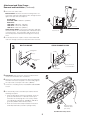
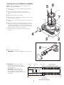
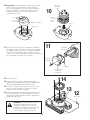
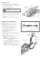
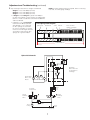
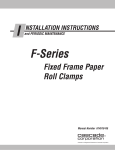
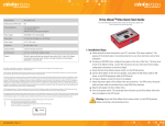
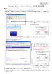
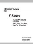
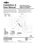
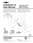
Attachment and Drive Group –
Removal and Installation
CW
This sheet provides installation instructions for service kits
6839416 and 6839420. Service kit 6839416 includes a
preassembled spring stack and a preassembled cover with
dowel pins, seal collar with seals, pressure plates, friction
discs, piston and brake rotor. Service kit 6839420 includes a
seal collar with seals. After servicing the brake components,
perform the Rotation Drift Test. Also included is a disabling
brake procedure (for temporary circumstances only) and
a troubleshooting section. Perform troubleshooting prior
contacting Cascade Service.
Rotator Drive Assembly
Service Kits 6839416 and
6839420
CC
W
c
Installation
Instructions
NOTE: Service Kit
6839420 can only
be installed in end
covers stamped
with “6830562”.
RC4737.eps
1 If possible, rotate the attachment to the vertical roll handling
position. Extend the arms outside the width of the frame.
WARNING: Before removing any hoses,
relieve pressure in the hydraulic system.
With the truck off, open the truck auxiliary
control valve(s) several times in both
directions.
2 Disconnect and plug the hydraulic supply hoses to the
attachment. Tag hoses for reassembly.
Rotate CCW
Rotate CCW
Rotate CW
Rotate CW
Clamp
Clamp
RC1816.eps
RC0441.eps
Open
Open
Single Drive
Back (Driver’s) View
Dual Drive
Back (Driver’s) View
cascade
W
corporation
For Technical Support . . .
To Order Parts . . .
Call: 1-800-227-2233
Fax: 1-888-329-8207 Call: 1-888-227-2233
Fax: 1-888-329-0234
Internet: www.cascorp.com Internet: www.cascorp.com
Write: Cascade Corporation, PO Box 20187, Portland, OR 97294
Write: Cascade Corporation, 2501 Sheridan Ave., Springfield, OH 45505
Attachment and Drive Group –
Removal and Installation (Continued)
3 Disconnect the lower hooks:
Bolt-On Hooks – Remove the lower mounting hooks. For
reassembly, tap hooks tight against lower carriage bar and
tighten the capscrews to a torque of:
4
Single Drive:
CL IV 90F, 100F – 260 ft.-lbs. (350 Nm)
Dual Drive:
120F-150F – 200 ft.-lbs. (270 Nm)
160F CL IV – 235 ft.-lbs. (320 Nm)
160F CL V – 250 ft.-lbs. (340 Nm)
Quick-Change Hooks – Pull out the locking pins and drop
the lower hooks to the unlocked position. Reinstall the pins
in the lower holes. For reassembly, slide the hooks up to
the locked position and install the locking pins in the top
holes.
3
Lower Hooks
RC4738.eps
4 Set the attachment on a pallet.
Tilt the mast forward and
lower the carriage to remove the attachment from the truck.
3
BOLT-ON HOOKS
QUICK-CHANGE HOOKS
Carriage Bar
Guide
RC0368.eps
RC0367.eps
®
T
US
J
AD
e
ad
sc
LH Lower
Hook
ca
-1
14
55
67
C-
LH Lower Hook
Locked Position
Locking Pin
5
5 Dual Drives – Disconnect the crossover tubes from the
check valve and brake valve assemblies.
6 Remove the capscrews fastening the drive assembly with
the brake valve to the baseplate. For reassembly, tighten
the capscrews to a torque of 75 ft.-lbs. (100 Nm).
7 Continue to “Installing Service Kits 6839416 and 6839420”
section.
8 For reassembly, reverse the above procedures with the
following exceptions:
• After the drive group has been reinstalled, check the
gearcase lubricant level. Lubricant must be up to
the bottom of the fill plug hole. If necessary, fill with
Cascade Gear Lube Part No. 656300, or SAE 90 wt.
gear lube (AGMA ‘mild’ 6 EP Gear Lube).
CCW
CW
• Refer to F-Series Roll Clamp Installation Instructions
674510 (Fixed Frame) or 674511 (Swing Frame).
RC4344.eps
6
Drive Assembly
with Brake Valve
(LH shown)
Dual Drive Roll Clamp shown
2
5 6
Installing Service Kits 6839416 and 6839420
NOTE: Service Kit 6839420 can only be installed in end
covers stamped with “6830562”.
1 Perform section “Attachment and Drive Group Removal
and Installation”.
Cover Plate
2 Lay the drive group, pinion down, on two 4 x 4 in.
(10 x 10 cm) wood blocks placed on both sides of the
pinion.
3 Remove brake tube. Do not discard.
4 Remove the three capscrews fastening the end cover to the
7
housing. Remove end cover.
Housing
5 Remove the four capscrews fastening the cover plate to the
housing.
6 Remove the center capscrew plug from the cover plate
RC4739.eps
and install a (early) 3/8 in. NC or (later) M10 capscrew with
a minimum thread length of 2 in. (50 mm). Remove the
cover plate by turning the capscrew clockwise while lightly
tapping around the sides of the cover plate.
7 Turn drive group over and drain the lubricant from the
housing.
4
2
3
8
8 Remove brake components.
Remove brake
components
IMPORTANT: If installing Kit 6839420, keep components.
9 Kit 6839416 – Verify kit spring stack
Spring Seat
RC4740.eps
Guide Rod
disc springs are oriented (as shown)
and the overall length is 5.937 ±0.003 in.
(150.8 ±0.08 mm).
Shims
Washer
Note each Disc
Spring’s orientation
Kit 6839420 – Inspect drive group
disc springs for damage and verify
the overall length is 5.937 ±0.003 in.
(150.8 ±0.08 mm). Replace disc springs
as needed.
5.937 ±0.003 in.
(150.8 ±0.08 mm)
Disc Spring Stack Diagram
RC4741.eps
3
10 Kit 6839420 – Use tool 6839417 to remove the seal collar
Brake Rotor
Assembly
from the end cover. Install new seal collar, using the
tool to seat and tighten into the end cover to a torque of
120 ft.-lbs. (160 Nm). Seat the piston in the seal collar.
Stack pressure plates, friction discs and brake rotor
assembly into the cover.
10
Pressure
Plates and
Friction
Discs
Tool 6839417
Piston
Seal Collar
RC4743.eps
RC4742.eps
11
11 Apply Loctite 515 sealant (Cascade Part No. 668184) to
both surfaces of the new end cover gasket (Cascade Part
No. 6805513) and the capscrews. Install the assembled
end cover with components, gasket, spring stack and
capscrews, as shown. Tighten the capscrews to a torque of
65 ft.-lbs. (90 Nm). Remove excess sealant.
Assembled
Spring Stack
RC4744.eps
End Cover
Capscrew
Gasket
End Cover with
assembled
components
14
12 Install brake tube.
13 With the gearcase laying flat, fill with 56 fluid ounces
(540 ml) of Cascade Gear Lube Part No. 656300, or SAE
90 wt. gear lube (AGMA ‘mild’ 6EP Gear Lube).
14 Install the cover plate and O-ring. Install the four cover
13
plate capscrews and tighten to a torque of 15 ft.-lbs.
(20 Nm). Install the center hole plug.
15 Reinstall drive group to baseplate and attachment to truck
by reversing the steps in section “Attachment and Drive
Group Removal and Installation”. Perform ”Adjustment &
Troubleshooting” Section.
12
Brake Tube
WARNING: After completing any service
procedure, always test the attachment
through five complete cycles. First test
the attachment empty, then test with a load
to make sure the attachment operates
correctly before returning it to the job.
4
RC4745.eps
Disabling Brake Circuit
The following steps are for temporarily disabling the brake
circuit for a short term.
1 Perform section “Attachment and Drive Group
Removal and Installation”.
2 Lay the drive group, pinion down, on two
5
4 x 4 in. (10 x 10 cm) wood blocks placed
on both sides of the pinion.
Spring Seat
3 Remove brake tube. Do not discard.
Guide Rod
4 Remove the three capscrews fastening
the end cover to the housing. Remove
end cover.
5 Remove the piston with seal, friction
disks, pressure plates, brake rotor
assembly, guide rod, disc springs and
spring seat.
Brake Rotator
Assembly
Piston
with
Seal
Friction Discs &
Pressure Plates
NOTE: The seal collar in the end
cover does not need to be removed,
if equipped.
4
both surfaces to a new end cover gasket (Cascade Part
No. 6805513) and the capscrews. Install the gasket and
end cover. Tighten the capscrews to a torque of 65 ft.-lbs.
(90 Nm). Remove excess sealant.
7 Cap brake fittings on brake valve and end cover with No. 4
metal caps.
8 Reinstall drive group and attachment to truck by reversing
the steps in “Attachment and Drive Group Removal and
Installation”.
2
7
3
6 Apply Loctite 515 sealant (Cascade Part No. 668184) to
6
LH Drivebox
Brake Valve
(shown)
WARNING: After completing any service
procedure, always test the attachment
through five complete cycles. First test
the attachment empty, then test with a load
to make sure the attachment operates
correctly before returning it to the job.
7
7
Brake crossover
tube fitting
RC4346.eps
Disc Springs
Brake crossover
tube fitting
RC4347.eps
Brake crossover
tube fitting
W
CC
CW
RH Drivebox
Brake Valve
Single Drive
Brake Valve
Solenoid
Brake Valve
5
RC4351.eps
Rotation Drift Test
Place a mark at the top center of the baseplate and rotate
bearing. Place rotation limit marks at 10°, approximately 6 in.
(15 cm), each side of top center on the faceplate. All marks
should be viewable by the driver.
Mark at
top center
Marks at 10°
(6 in., 15 cm)
each side of
center
• Clamp roll with pads at bottom of roll.
WARNING: Make sure all personnel are
clear of the attachment during testing.
• Lift roll 15 in. (38 cm) off floor to provide clearance for rotation
drift test.
• Rotate roll 10° CW and wait 30 sec. No drift is allowed.
• Rotate roll 10° CCW and wait 30 sec. No drift is allowed.
• If roll drift occurs, troubleshoot brake as described in the
section below.
RC4704.eps
NOTE: If the brake circuit is disabled, contact Cascade.
Adjustment and Troubleshooting
NOTE: Refer to the schematic on the following page.
Pressure
Gauge*
Truck Requirements – Review attachment hydraulic
specifications in F-Series Service Manual 674512.
No. 6-6 Hose*
Tools required – In addition to a normal selection of
mechanic’s hand tools, the following are required:
No. 6 and No. 8
JIC Swivel Tee
GA0014.eps
No. 4-6 Pipe/JIC*
• Pressure Gauge Kit (3 kits required):
5000 psi (345 bar) – Cascade Part No. 671212.
• Assorted fittings and hoses, as required.
No. 6-8 JIC
Reducer
No. 4, No.
6* and No. 8
JIC/O-Ring
Pressure Gauge Kit 671212
Troubleshooting Procedure – Perform the following
troubleshooting steps:
1 Install the three pressure gauges and tee fittings to the
rotator motor fittings and brake drive fitting. Replace brake
drive tube with a hose.
2 With gauges installed, rotate the attachment CCW.
rotation the gauges should read:
Gauge 1
(Rotate CCW)
During
Gauge 2
(Rotate CW)
Gauge 1 – High, up to 2300 psi (160 bar)
Gauge 2 – Low, approximately 200 psi (14 bar)
Gauge 3 – Between 700-1000 psi (48-70 bar), must not
exceed 1000 psi (70 bar)
Gauge 3
(Brake Pilot Line)
Replace tube with
hose and tee fitting.
• If rotation is jerky and Gauge 3 is less than 700 psi
(48 bar) while rotating, turn in the relief cartridge on the
drive motor valve to bring the pressure within the range
of 700-1000 psi (48-70 bar).
CW
CC
W
• If Gauge 3 is greater than 1000 psi (70 bar) while
rotating, turn out the relief cartridge on the valve to bring
pressure within the range of 700-1000 psi (48-70 bar).
RC4746.eps
6
Adjustment and Troubleshooting (continued)
3 Stop rotating the attachment. Gauges should read:
NOTE: If further troubleshooting is required, before contacting
Cascade, record all gauge readings.
Gauge 1 – Less than 300 psi (21 bar)
Gauge 2 – Less than 300 psi (21 bar)
Gauge 3 – Less than 300 psi (21 bar)
• If Gauge 1 and/or Gauge 2 is greater than 300 psi
(21 bar), the hydraulic system requires an independent
tank line. Install Cascade Pressure Relief Kit 6043749
and hose 207299.
• If drifting occurs and all gauges
read less than 300 psi (21 bar)
while drifting occurs, verify that
the disc springs are stacked in
the correct orientation, as shown.
Check the overall length and shim
as required. Verify that the disc
springs are in good condition.
Disc Spring Stack Diagram
Spring Seat
Guide Rod
Shims
Washer
Note each Disc
Spring’s orientation
150.8 ±0.08 mm
RC4741.eps
Hydraulic Schematic
Dual Drive
Brake Valve with
Counterbalance
Cartridges
Rotator Dual
Drives and
Motors
2-Port
Hose
Reel
To Clamp
Components
Clamp
Auxiliary
Valve
Truck
Pump
Rotate
Auxiliary
Valve
Truck
Relief
Truck
Tank
RC4942.eps
7
Do you have questions you need
answered right now? Call your nearest Cascade Service Department.
Visit us online at www.cascorp.com
AMERICAS
Cascade Corporation
U.S. Headquarters
2201 NE 201st
Fairview, OR 97024-9718
Tel: 800-CASCADE (227-2233)
Fax: 888-329-8207
Cascade Canada Inc.
5570 Timberlea Blvd.
Mississauga, Ontario
Canada L4W-4M6
Tel: 905-629-7777
Fax: 905-629-7785
Cascade do Brasil
Rua João Guerra, 134
Macuco, Santos - SP
Brasil 11015-130
Tel: 55-13-2105-8800
Fax: 55-13-2105-8899
EUROPE-AFRICA
Cascade Italia S.R.L.
European Headquarters
Via Dell’Artigianato 1
37030 Vago di Lavagno (VR)
Italy
Tel: 39-045-8989111
Fax: 39-045-8989160
Cascade (Africa) Pty. Ltd.
PO Box 625, Isando 1600
60A Steel Road
Sparton, Kempton Park
South Africa
Tel: 27-11-975-9240
Fax: 27-11-394-1147
ASIA-PACIFIC
Cascade Japan Ltd.
2-23, 2-Chome,
Kukuchi Nishimachi
Amagasaki, Hyogo
Japan, 661-0978
Tel: 81-6-6420-9771
Fax: 81-6-6420-9777
Cascade Korea
121B 9L Namdong Ind.
Complex, 691-8 Gojan-Dong
Namdong-Ku
Inchon, Korea
Tel: +82-32-821-2051
Fax: +82-32-821-2055
Cascade-Xiamen
No. 668 Yangguang Rd.
Xinyang Industrial Zone
Haicang, Xiamen City
Fujian Province
P.R. China 361026
Tel: 86-592-651-2500
Fax: 86-592-651-2571
Cascade Australia Pty. Ltd.
1445 Ipswich Road
Rocklea, QLD 4107
Australia
Tel: 1-800-227-223
Fax: +61 7 3373-7333
Cascade New Zealand
15 Ra Ora Drive
East Tamaki, Auckland
New Zealand
Tel: +64-9-273-9136
Fax: +64-9-273-9137
Sunstream Industries
Pte. Ltd.
18 Tuas South Street 5
Singapore 637796
Tel: +65-6795-7555
Fax: +65-6863-1368
Cascade India Material
Handling Private Limited
No 34, Global Trade Centre
1/1 Rambaugh Colony
Lal Bahadur Shastri Road,
Navi Peth, Pune 411 030
(Maharashtra) India
Phone: +91 020 2432 5490
Fax: +91 020 2433 0881
c
© Cascade Corporation 2013
09-2013
Part Number 6840889-R1