1
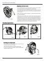
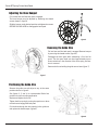
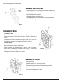
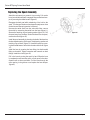
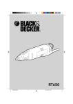
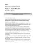
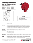
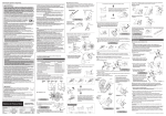
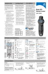
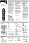
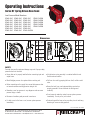
Operating Instructions
Series RT Spring Driven Hose Reels
Low Pressure Model Numbers:
RT402-OLP
RT403-OLP
RT405-OLP
RT406-OLP
RT602-OLP
RT603-OLP
RT605-OLP
RT802-OLP
RT803-OLP
RT805-OLP
RT425-OLP
RT435-OLP
RT450-OLP
RT465-OLP
RT625-OLP
RT635-OLP
RT650-OLP
RT825-OLP
RT835-OLP
RT850-OLP
RT450-OLPSM
RT635-OLPSM
RT650-OLPSM
RT825-OLPSM
RT835-OLPSM
RT850-OLPSM
Dimensions
A 17 7/8”
A
B 16 1/2”
B 16 7/16”
C
6”
C 16 11/16”
D
2 1/4”
D 3 5/16”
E
See
page 6
E
18”
See
page 7
SAFETY
Personal injury and/or equipment damage may result if proper safety
precautions are not observed.
•Ensure that reel is properly installed before connecting input and
output hoses.
•A high tension spring assembly is contained within the reel.
Exercise extreme caution.
•Bleed fluid/gas pressure from system before servicing reel.
•Pull hose from reel by grasping the hose itself, not the control
valve.
•Before connecting reel to supply line, ensure that pressure does
not exceed maximum working pressure rating of reel.
•Remember, even low pressure is very dangerous and can cause
personal injury or death.
•Ensure that reel, hose, and equipment being serviced are
properly grounded. Use an ohmmeter to check ground
continuity.
•Be aware of machinery and personnel in work area.
•If reel ceases to unwind or rewind, remove system pressure
immediately. Do not pull or jerk on hose!
•If a leak occurs in the hose or reel, remove system pressure
immediately.
•Treat and respect the hose reel as any other piece of machinery,
observing all common safety practices.
Form# 1121-802A Rev: 9/2015
Reelcraft Industries, Inc. • 2842 E Business Hwy 30, Columbia City, IN 46725
Ph: 800-444-3134 / 260-248-8188 • Fax: 800-444-4587 / 260-248-2605
Customer Service: 855-634-9109 • [email protected] • www.reelcraft.com
Series RT Spring Driven Hose Reels
Mounting the Hose Reel
Prior to mounting the hose reel, ensure that the supply line pressure does
not exceed the maximum working pressure of the hose reel.
Do not exceed the maximum installation height of 16’ unless the reel was
specified differently when ordering. The maximum operating temperature
is 150 °F (66 °C).
Unpack and inspect the reel for damage. Turn the spool by hand to check
for a smooth operation.
figure 1
Position the reel on the floor, wall or ceiling. Secure into place using four
mounting bolts (not included). See the included mounting template for
additional instructions for your specific mounting application. Depending
on where the reel is placed, it may be necessary to adjust the hose bumper
and guide arm to use the hose properly. See the instructions on the next
page to adjust the hose bumper and reposition the guide arm.
Mounting Applications
figure 2
figure 3
figure 4
Installing the Input Hose
Use a flexible hose connection at input. Do not use rigid
plumbing. (input hose not included)
Apply pipe thread sealant to threads on standard reels.
Do not over tighten the connection. Recommended torque
should not exceed 70 ft./lb.
figure 5
Page 2
www.reelcraft.com
Series RT Spring Driven Hose Reels
Adjusting the Hose Bumper
Pull out the hose until the latch pawl is engaged.
The hose bumper may be adjusted by loosening the slotted
screws shown in figure 6.
Slide the bumper to the desired position and tighten the screws
BEFORE PULLING HOSE to disengage the latch pawl.
figure 6
Removing the Guide Arm
Pull out hose until the latch pawl is engaged. Remove bumper
by removing the slotted screws (figure 6).
Disengage the latch pawl while maintaining a firm hold on
spool. Turn the spool hand over hand approximately two or
three revolutions in the direction of the drive spring until tension is removed.
Remove the 4 nuts holding the guide arm to base (figure 7).
figure 7
Positioning the Guide Arm
Remove the guide arm and adjust to any of the seven
positions shown in figure 8.
See figures 2, 3, and 4, for recommended Guide Arm
positions for each mounting application.
Replace and tighten the 4 nuts.
Tighten the drive spring by turning the spool two or three
revolutions and engage the latch pawl.
Pull the hose through the roller opening in the guide arm
and replace the hose bumper (figure 6)
figure 8
www.reelcraft.com
Page 3
Series RT Spring Driven Hose Reels
Replacing the Latch Pawl
Remove the guide arm by following the procedure for “Removing
the Guide Arm”. Remove the retaining nut as shown in figure 9.
Replace the latch pawl assembly.
Replace and tighten the retaining nut.
Replace the guide arm and hose bumper by following the procedure for “Positioning the Guide Arm”.
figure 9
Replacing the Hose
To remove the hose
Pull out the hose leaving 2 to 3 feet on the spool. Engage the latch pawl.
Remove the U-bolt nuts on the inside of the spool (figure 10). Remove the
U-bolt.
Unthread the hose at the connection to the swivel tube. Use a wrench on
both fittings or the swivel may be damaged. Remove the hose.
To install the hose
Route the hose through the guide arm rollers and opening of the spool.
Apply thread tape or sealant to hose threads.
Screw hose fitting into threaded fitting on swivel. Tighten connection
with a wrench on both fittings. Install the U-bolt (figure 10). Install hose
bumper on working end of hose if required.
figure 10
Disengage latch pawl and allow hose to retract.
Replacing the Swivel
Remove the hose.
See the procedure for “Replacing the Hose”.
Remove swivel by unscrewing the threaded stem from the
main shaft (figure 11).
Replace swivel by screwing threaded stem of swivel into
main shaft of reel. Replace the hose.
figure 11
Page 4
www.reelcraft.com
Series RT Spring Driven Hose Reels
Replacing the Spool Assembly
Attach the reel securely to prevent it from moving. Pull out the
hose just until the latch pawl is engaged. Remove the hose bumper by removing the slotted screws (figure 6).
Disengage the latch pawl while maintaining a firm hold on the
spool. Turn the spool hand over hand approximately two or three
revolutions until the spring tension is removed.
Unscrew the swivel stem from the main shaft. Next, remove
the swivel by unscrewing the swivel from the hose (figure 11).
Remove the retaining ring and spacing washer (figure 12). Pull
the spool away from the base. Unwind the hose from the spool,
remove the u-bolt (figure 10).
figure 12
Install the spool assembly by inserting the shaft of the base into
the hex shaped opening of the spool. Install spacing washer and
retaining ring as shown (figure 12). Install the swivel by screwing the threaded stem of swivel into the main shaft of reel (figure
11).
Install the hose by screwing the hose fitting into the threaded
fitting on the swivel. Tighten connection with a wrench on both
fittings. Install the u-bolt (figure 10).
Pull in the hose by turning the spool by hand. When the hose
is completely wound onto the spool, turn the spool in the other
direction two to three revolutions. Pull the hose through the
roller opening in the guide arm and replace the hose bumper
(figure 6).
www.reelcraft.com
Page 5
Series RT Spring Driven Hose Reels
Item
#
Description
#
Req.
1 1/4-20 Lock Nut
2
3 Spool Assembly
1
4 U-Bolt
1
5 Latch Pawl Assembly 1
6 Guide Arm Assembly 1
7 Nut 1/2”
1
8 Hose Bumper
1
9 Hose Assembly
1
10 Nut 5/16”
4
1
11 Base Assembly
12 Spacing Washer
1
13 Snap Ring
1
14 Swivel Assembly
1
“E” Dimensions - See page 1
RT402-OLP RT403-OLP RT405-OLP RT406-OLP RT602-OLP RT603-OLP RT605-OLP RT802-OLP RT803-OLP RT805-OLP
Item
#
Description
#
Req.
1 1/4-20 Lock Nut
2
3 Spool Assembly
1
4 U-Bolt
1
5 Latch Pawl Assembly 1
6 Guide Arm Assembly 1
7 Nut 1/2”
1
8 Hose Bumper
1
9 Hose Assembly
1
10 Nut 5/16”
4
11 Base Assembly
1
12 Spacing Washer
1
13 Snap Ring
1
14 Swivel Assembly
1
“E” Dimensions - See page 1
RT425-OLP RT435-OLP RT450-OLP RT465-OLP RT625-OLP RT635-OLP RT650-OLP RT825-OLP RT835-OLP RT850-OLP
Page 6
261650-1
S600827
3-117440
S600823
S600825
S76-108
None
None
261650-2
600824
300034
300031
S600886
5 3/4”
261650-1
S600827
3-117440
S600823
S600825
S76-108
261650-1
S600827
3-117440
S600823
S600825
S76-108
None
None
261650-2
600824
300034
300031
S600886
5 3/4”
261650-1
S600827
3-117440
S600823
S600825
S76-108
261650-1
S600860
3-117440
S600823
S600825
S76-108
None
None
261650-2
600824
300034
300031
S600886
5 3/4”
261650-1
S600860
3-117440
S600823
S600825
S76-108
261650-1
602239
3-117440
S600823
S600825
S76-108
None
None
261650-2
600824
300034
300031
S600886
5 3/4”
261650-1
602239
3-117440
S600823
S600825
S76-108
1-HR1004-A 1-HR1004-A 1-HR1004-A 1-HR1004-A
261650-1
S600827
3-117440
S600823
S600825
S76-108
None
None
261650-2
600824
300034
300031
S600886
5 3/4”
261650-1
S600827
3-117440
S600823
S600825
S76-108
1-HR1004
261650-1
S600827
3-117440
S600823
S600825
S76-108
None
None
261650-2
600824
300034
300031
S600886
5 3/4”
261650-1
S600827
3-117440
S600823
S600825
S76-108
1-HR1004
261650-1
S600828
3-117440
S600823
S600826
S76-108
None
None
261650-2
600833
300034
300031
S600886
6 1/4”
261650-1
S600828
3-117440
S600823
S600826
S76-108
1-HR1004
261650-1
S600879
3-117440
S600823
S600826
S76-108
None
None
261650-2
600833
300034
300031
600914-1
6 1/4”
261650-1
S600879
3-117440
S600823
S600826
S76-108
261650-1
S600879
3-117440
S600823
S600826
S76-108
None
None
261650-2
600833
300034
300031
600914-1
6 1/4”
261650-1
S600879
3-117440
S600823
S600826
S76-108
261650-1
602011
3-117440
S600823
602014
S76-108
None
None
261650-2
602012
300034
300031
600914-1
7 3/4”
261650-1
602011
3-117440
S600823
602014
S76-108
2-HR1004-3 2-HR1004-3 2-HR1004-3
601001-25 601001-35 601001-50 601000-65 601013-25 601013-35 601013-50 601020-25 601022-35 601022-50
261650-2 261650-2 261650-2 261650-2 261650-2 261650-2 261650-2 261650-2 261650-2 261650-2
600824
600824
600824
600824
600824
600824
600833
600833
600833
602012
300034
300034
300034
300034
300034
300034
300034
300034
300034
300034
300031
300031
300031
300031
300031
300031
300031
300031
300031
300031
S600886
S600886
S600886
S600886
S600886
S600886
S600886 600914-1 600914-1 600914-1
5 3/4”
5 3/4”
5 3/4”
5 3/4”
5 3/4”
5 3/4”
6 1/4”
6 1/4”
6 1/4”
7 3/4”
www.reelcraft.com
Series RT Spring Driven Hose Reels
Item
#
Description
#
Req. RT450-OLPSM RT635-OLPSM RT650-OLPSM RT825-OLPSM RT835-OLPSM RT850-OLPSM
1 1/4-20 Lock Nut
2
261650-1
261650-1
261650-1
261650-1
261650-1
261650-1
3 Spool Assembly
1
S600860
S600827
S600828
S600879
S600879
602011
4 U-Bolt
1
3-117440
3-117440
3-117440
3-117440
3-117440
3-117440
5 Latch Pawl Assembly
1
S600823
S600823
S600823
S600823
S600823
S600823
6 Guide Arm Assembly
1
S600825
600825
S600826
S600826
S600826
602014
7 Nut 1/2”
1
S76-108
S76-108
S76-108
S76-108
S76-108
S76-108
8 Hose Bumper
1
1-HR1004-A
1-HR1004
1-HR1004
2-HR1004-3
2-HR1004-3
2-HR1004-3
9 Hose Assembly
1
601001-50
S601013-35
S601013-50
601020-25
601022-35
601022-50
10 Nut 5/16”
4
261650-2
261650-2
261650-2
261650-2
261650-2
261650-2
11 Shaft / Bracket Assembly 1
602263
602263
600264
602264
602264
602265
12 Spacing Washer
1
300034
300034
300034
300034
300034
300034
13 Snap Ring
1
300031
300031
300031
300031
300031
300031
14 Swivel Assembly
1
602262
602262
602262
602311
602311
602311
8 5/8”
“E” Dimensions - See page 1
6 1/8”
7 5/16”
7 5/16”
7 5/16”
7 5/16”
www.reelcraft.com
Page 7