1
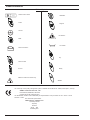
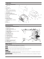
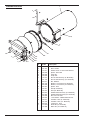
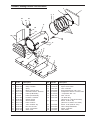
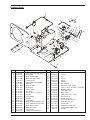
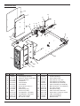
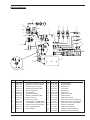
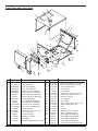
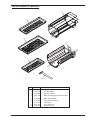
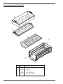
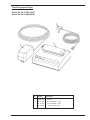
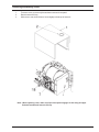
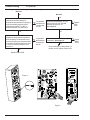
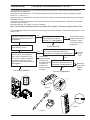
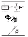
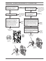
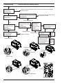
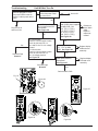
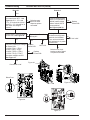
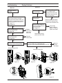
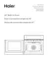
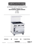
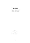
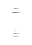
P
A
R
T
S
L
I
S
T
Delta-XL - 8"
&
S
E
R
V
I
C
E
Delta-XL - 10"
G
U
I
D
E
www.pelton.net
Product Information
Table of Symbols
On/Off Power Switch
Clear/Start
Power
Program
Ground
Hot Surface
Mode
Low Water
Printer Connection
Dry
Printer On/Off
Arrows
Ready
Attention: Printer Connection Only
Sterilize
The conformity of the quality management system is certified with Certificate No. 369CE, dated April 8, 1999 by:
AMTAC Certification Services, LTD
Norman Road, Broadheath, Altrincham
Cheshire WA 14 4EP, United Kingdom
The identification number of the notified body for implementation of the procedure set out in Annex V of the
Directive is 0473.
The authorized representative :
Medical Device & QA Services
76, Stockport Road
Timperley
Cheshire
WA15 7SN
United Kingdom
2
Visual Index
1
2
3
4
5
6
7
8
9
10
11
12
13
14
15
16
17
18
Casing with Plumbing Diagram
(inside cover)
Fill
Front Frame
Door with Lock
Drain
(quick connection behind door)
Front Panel Microprocessor MPU
Power PCB
RTD (Steam) Sensor
Reservoir with Overflow Vent
Water Level Switch (inside reservoir)
Printer Jack
Solenoids
Drying Pump
Master Power Switch
Heating Element
(mounted on bottom of chamber)
Safety Valve
Filter
Transformer
Operating Features
1.
2.
3.
4.
5.
6.
7.
8.
9.
10.
11.
12.
13.
14.
15.
16.
17.
18.
19.
20.
Power Switch/Circuit Breaker (rear of unit)
Reservoir Fill
Operation Indicator Light
Display Window (Pressure) kPa
Arrow Switches
Display Window (Temp/Time) C/F / Minutes
Clear/Start Switch
Low Water Light
Mode Selection Switch
Mode/Program Display
Power On Switch
Programming Switch
Printer On/Off Switch
Quick Drain Connection (inside door)
Leveling Feet
Door Lock
Safety Valve (rear corner of unit)
Operating Instructions Label
Caution Label
Serial Number Plate (inside door)
Safety Features
The design of the autoclave has these safety features for your protection:
Door Lock
Door can be opened only when internal pressure is at atmospheric pressure.
Vent Valve
The vent valve will open and the P-2 alarm will display should the chamber pressure exceed 240 kPa.
Safety Valve
The safety valve opens as backup protection should the chamber pressure exceed 262 kPa.
Overheat Protection
Chamber temperature is protected with a surface sensor so the temperature will not exceed 159°C. It has additional overheat protection
should the temperature of the heating elements reach 180°C.
Electrical Power Interruption
In case of a power failure during the sterilization cycle, pressure in the chamber is automatically vented to the atmosphere and display is
blank.
3
Chamber and Door
7
6
5
8
9
10
3
11
4
12
13
14
2
1
17
16
15
No.
Part No.
1
2
3
4
5
6
7
15 39 845
41 97 245
01 97 54
15 39 258
41 96 809
15 39 589
41 97 112
41 97 179
30 00 077
42 05 790
42 05 808
33 22 281
15 39 241
15 39 407
42 03 845
42 03 985
15 39 928
15 39 894
15 39 514
15 39 720
54 69 635
51 74 870
51 74 888
8
9
10
11
12
13
14
15
16
17
4
Description
Screw- Button Hd. 1/4 20 x .375"
Stud- Handle
Washer- Shim 1.0 oDX 15/32 IDX.016
Spacer- latch slide
Hinge Pin
E-Clip 3/8"
Door & Chamber Assy. (8"- Model AE)
Door & Chamber Assy. (10"- Model AF)
Nut- Retainer
Bracket- Lever switch (8"- Model AE)
Bracket- Lever switch (10"- Model AF)
Spacer- Door
Seal (8"- Model AE)
Seal (10"- Model AF)
Gasket Retain Stud Assy. (8"- Model AE)
Gasket Retain Stud Assy.(10"- Model AF)
Nut- Hex 41H 2520
Lock Washer- .26IDX.43ODX.05 STL
Insulation- Door (8"- Model AE)
Insulation- Door (10"- Model AF)
Locking Pin- 8x10
Slide- Bar (8"- Model AE)
Slide- Bar (10"- Model AF)
Chamber, Heating Element And Insulation
3
2
3
2
22
23
1
24
11
25
26
4
18
19
20
17
21
15
8
13
6
12
5
16
10
14
7
9
No.
1
2
3
4
5
6
7
8
9
10
11
12
13
14
Part No.
15 39 670
30 05 035
15 39 472
15 39 647
15 21 512
41 91 826
019769
54 27 906
33 25 094
15 31 628
15 21 158
42 00 346
15 39 803
42 05 816
42 05 782
Description
Insulation- Rear
Strap- Insulation
Spring
Band- Pressure Plate
Overheat Protector- Chamber
Heater (8"-Model AE)
Heater (10"-Model AF)
Insulation- Chamber
Surface Sensor
Sensor Bracket
Plate- Pressure
Tube- Chamber Top
Nut- Hex 41H-440
Cover- Level Switch
Switch Lever
No.
Part No.
15
16
17
18
19
20
21
22
15
15
18
30
41
41
18
42
39
39
81
00
96
96
81
07
969
712
023
036
767
759
031
432
23.1
42 07 424
23.2
24
25
26
15
42
15
15
39
05
36
29
324
055
486
267
Description
Phillips Hd. Screw- 4-40 x 1"
Spacer- Door Switch
Tube- Chamber
Round Head Screw- 8-32 x .375
Compression Sleeve- Pressure Plate
Compression Nut- 1/4"
Filter- Fill Line
1/4" Brass Plug
(Siemens 115, 230V & TUV 230V)
Elbow- 1/2 St 1/4 Tap
(Siemens 115, 230V & TUV 230V)
Elbow- 1/2 St (Delta-XL 115V)
Value- Safety Relief/Chain
Nipple- 1/2 NTPx4
Tube- Relief
5
Reservoir Parts
24
25
13
23
11
12
8
9
12
15
16
10
17
18
22
19
7
6
4
3
14
5
21
2
1
20
No. Part No.
1
33 39 913
2
41 96 924
41 96 999
3
18 81 056
4
18 81 064
5
15 39 449
6
18 81 072
7
33 25 052
8
30 00 002
9
15 39 613
10
42 05 899
41 97 021
11
94 42 930
12
94 42 724
6
Description
Reservoir
Tube - Bel to Res (8"-Model AE)
Tube - Bel to Res (10"-Model AF)
Nut - Compression (5/16")
Sleeve - Compression, Tapered
Coupling - Vent Condenser
O-ring
Water Level Assembly
Washer - Flat
Nut - Air Valve
Tube- Dump to Res (8"-Model AE)
Tube- Dump to Res (10"-Model AF)
Dump Solenoid
Connector
No.
Part No.
13
41 97 047
41 97 039
15 39 563
18 81 080
18 81 098
18 81 106
94 32 311
15 26 412
41 96 932
41 96 965
15 35 587
94 35 546
15 39 746
41 96 841
94 42 732
14
15
16
17
18
19
20
21
22
23
24
25
Description
Tube - Chamber/Dump (8"-Model AE)
Tube - Chamber/Dump (10"-Model AF)
Washer - Rubber
Nut - Condenser Tube
Sleeve - Compression
Condenser - 4 Coil
Filter - Reservoir
Nut - Air Valve
Tube - Reservoir to Fill (8"-Model AE)
Tube - Reservoir to Fill (10"-Model AF)
Gasket - Support
O-ring
Cap Reservoir
Reducer
Tee-- Compession 5/16
Plumbing Parts
42
35
36
33
32
34
31
21
6
5
7
4
24 37
25
22
25
38
24
30
21
26
27
28
40
41
23
8
25
24
39
29
13
18
3
19
4
20
1
2
10
9
15
16
14
17.1
17.2
12
11
No.
1
2
3
4
5
6
7
8
9
10
11
12
13
14
15
16
17.1
17.2
18
19
20
21
Part No.
41
33
15
15
41
15
15
94
15
15
94
15
41
30
30
42
33
33
42
42
41
94
93
39
22
22
96
39
39
42
22
39
42
39
97
00
00
07
25
38
05
05
97
48
376
947
502
494
973
381
274
906
510
365
815
829
146
051
028
416
086
683
923
915
138
598
Description
Drain Hose Assy. (Incl. 2,3,4)
Tube Drain
Quick Connect Male
Quick Connect Female
Tube Fill to Ch
Elbow-White Polypropylene
Wire Tie
Hose Overflow
Hose Drain
Clamp - Hose
Pin Cotter
Ground Screw- 10-24 x .5
Air Filter
Lock Washer
Hex Nut
Pump Strap
Pump (Delta & Siemens 115V)
Pump (Siemens & TUV 230V)
Screw Button Head
GND Wire Pump
Holder-Filter
Tubing Connector-Short
No.
22
23
24
25
26
27
28
29
30
31
32
33
34
35
36
37
38
39
40
41
42
Part No.
41 96 817
30 00 044
18 81 056
18 81 064
94 42 740
15 39 837
94 42 922
54 40 610
54 40 602
94 42 948
41 96 981
041572
94 48 598
41 96 759
41 96 767
94 42 732
54 40 628
54 73 017
18 81 056
18 81 064
044176
Description
Bracket Valve
Screw
Nut
Sleeve
Elbow
Washer
Fill Solenoid
Elbow-900 5/16 x 1/8 Npt
Tube-1" Long x 5/16 O.D. x .049w Brs
Bellows Solenoid
Tube Bel to Ch
RTD Sensor
Tubing Connector - Long
Nut 1/4 Comp.
Sleeve 1/4 Comp.
Tee-Compression 5/16"
Barb-3/16 x 1/8 Npt
Check Valve
Compression Nut 5/16"
Compression Sleeve 5/16"
Clamp
7
Electrical Parts
3
21
1
12
14
4
5
19
9
20
6
8
7
10
22
14
11
18
14
16
23
13
15
24
No.
Part No.
1
2
3
4
5
6
7
8
9
044201
94 42 765
41 97 005
15 28 368
70 38 623
30 00 051
15 39 829
77 40 640
15 30 661
041277
46 99 190
46 92 208
33 25 110
30 00 028
10
11
12
8
2
17
Description
Power Supply PCB Assy
Extension- Spacer Circuit Board
Power PCB Guard
Transformer
Terminal Block
Lock Washer
Ground Screw- 10-24 x .5
Strain Relief
Power Cord (115V)
Power Cord ( 230V)
Circuit Breaker - 10A (230V)
Circuit Breaker - 20A (115V)
Cable- Printer Socket
Nut- Hex 41 H-1024
No.
Part No.
13
14
15
16
045835
42 05 923
15 25 331
045841
045455
42 05 881
041136
18 98 639
94 33 756
33 25 029
42 07 390
29 44 098
040788
045487
17
18
19
20
21
22
23
24
Description
Control PCB Guard
Screw- Button Head
Screw Pan Hd - 32 x 5/16"
Panel- Bottom (8"- Model AE)
Panel- Bottom (10"- Model AF)
MPU Control Assy. (8"- Model AE)
MPU Control Assy. (10"- Model AF)
Clip- Wire Harness
Heat Shrink Tubing
Cable- AC Power to Pwr PCB
Ground Wire- Terminal To Chasis
Label- Teminal Block
Front Panel PCB Assy.
Electrical Cover
Electrical Diagram
9
7
15
14
8
TOP
SIDE
6
16
17
10
12
11
4
18
3
5
RED
13
YELLOW
BLACK
20
19
P4
21
22
2
P7
WH
BK
WH
1
1
2
3
4
24
TB1
23
TB2
27
25
26
230V
No.
Part No.
1
2
3
4
5
6
7
8
9
15 28 368
40 05 915
42 07 390
42 07 374
15 39 274
70 38 623
29 44 098
42 07 382
15 30 661
041277
46 99 208
46 99 190
15 37 476
15 22 775
33 25 060
10
11
12
13
Description
Transformer 120/240V, 40VCT
GND Wire to Pump TO Chasis
GND Wire Term to Chasis
Wire Blu (Trm Blck/Crct Brk)
Wire Tie High Temp.
Terminal Block
Label Terminal Block
Wire Brn (Trm Blck/Crct Brk)
Power Cord 115V)
Power Cord ( 230V)
Circuit Breaker - 20 AMP (230V)
Circuit Breaker - 10 AMP (115V)
Cable AC Power to Power PCB
Power Supply PCB Assy
Cable Solenoid
No.
14
15
16
17
18
19
20
21
22
23
24
25
26
27
Part No.
94 42 930
94 42 948
94 42 922
33 25 052
041572
42 05 782
33 25 078
33 25 094
33 25 110
42 05 881
041136
15 37 492
41 91 818
019769
15 21 512
33 25 037
Description
Dump Solenoid
Bellow Solenoid
Fill Solenoid
Level Switch
RTD Sensor
Switch Lever
Cable Door Switch
Surface Sensor
Cable Printer Socket
MPU Control Assy. (8"- Model AE)
MPU Control Assy. (10"- Model AF)
Cable Assy- Power PCB to MPU
Heater (8"- Model AE)
Heater (10"- Model AF)
Chamber Overheat Protector
Wire Assy Over Heat Protector
9
Front Frame and Casing Parts
2
34
3
1
4
26
6
26
33
25
7
22
8
21
32
25
26
5
23
20
29
25
30
19
28
27
15
16
9
18
12
13
14
17
24
31
10
11
No.
Part No.
1
2
3
18 81 114
51 49 815
045840DW
045457DW
045843DW
045456DW
045841
045455
42 05 048
045842
045454
51 63 550DW
51 63 535DW
045488
30 00 010
15 39 985
045487
15 39 423
15 39 316
15 39 571
4
5
6
7
8
9
10
11
12
13
14
15
Description
Cup Reservoir Fill
Dou. Side Tape
Case (8"- Model AE)
Case (10"- Model AF)
Panel- Rear (8"- Model AE)
Panel- Rear (10"- Model AF)
Bottom Panel (8"- Model AE)
Bottom Panel (10"- Model AF)
Casing Gasket Set
Front Panel (8"- Model AE)
Front Panel (10"- Model AF)
Door Cover (8"- Model AE)
Door Cover (10"- Model AF)
Handle- Granite
Screw- Soc. Hd. 6-32 x .375
Cap- 8-32 x .375
Cover- Elect Assy.
Bushing- 1 5/16 ID
Nut- Speed
Bracket- Bottom Electronic Cover
No.
16
17
18
19
20
21
22
23
24
25
26
27
28
29
30
31
32
33
34
10
Part No.
15 36 445
30 00 036
15 39 902
30 00 077
15 39 852
30 00 069
15 39 183
42 00 338
045459
15 39 530
15 39 936
15 39 910
15 39 308
30 00 028
15 39 811
4206459
045844
045464
045845
045465
042912
Description
Rivet - Pop 8 CSNK 1/2 x .101/.130
Phil. Hd. Screw- 8-32 x .375 ZN
Screw- 85SS-1024-37
Nut- Retainer
Lock Washer
Screw- Mach. Rd. Hd. 8-32 x 1.25
Bracket- Top Electronic Cover
Reservoir Support
Cover- Bottom
Clip- Speed
Mach. Slotted Screw- 10-24 x .375
Mach. Slotted Scew- #10
Foot
Nut- Hex
Washer- 8 O.D. 2143 046
Glide- Adjustable Swivel
Brace- Right (8"- Model AE)
Brace- Right (10"- Model AF)
Brace- Left (8"- Model AE)
Brace- Left (10"- Model AF)
Operation Quick Reference Card
Tray and Tray Rest (8"- Model AE)
1
9
4
8
2
3
7
5
6
No.
Part No.
1
2
3
4
30 00
15 39
15 33
30 00
5
6
7
8
9
15
15
15
15
30
143
290
848
150
39 548
39 696
39 779
39 761
00 135
Description
Tray Rest (Delta 115V & TUV 230V)
Tray Rest (230V)
Clip-Tray Support
Baffle- Chamber (Delta 115V & TUV 230V)
Baffle- Export (230V)
Tray Handling Accessory
Tray- Export
Tray- Large Auto
Tray- Small Auto
11
Tray and Tray Rest (10"- Model AF)
1
2
3
4
5
6
No.
1
2
3
4
5
6
12
Part No.
15 39 340
15 39 357
044159
30 00 184
15 37 666
30 00 192
Description
Large Instrument Tray
Small Instrument Tray
Trayrest
Trayrest - Export
Clip- Tray Support
Splash Guard- Export
Time/Temperature Printer
Printer Kit- 54 37 590 (120V)
Printer Kit- 54 37 624 (240V)
3
1
2
No.
1
2
3
Part No.
54
54
54
54
37
39
75
30
525
166
533
595
Description
Printer
Power Adapter - 115V
Power Adapter - 230V
Cable - Printer Jack
13
Important Notes
•
Measurements
Instruments required
1. Digital multimeter model FLUKE 8000 A, or
equivalent.
Accuracy: AC voltage +- 0.5% of reading
plus 1 digit.
DC voltage +- 0.1% of reading
plus 2 digits.
DC current +- 0.3% of reading
plus 1 digit.
2. Testleads: Small needle point testleads are
required when voltage measurements are
performed at connectors which remain
plugged.
Always switch the unit OFF before connect
ing measuring instruments.
Select the correct type of current/voltage
and set the measuring range according to
the expected measured values.
Carry out continuity tests only with the unit
switched OFF.
•
Warm-up period & self-test
Do not press any buttons when switching ON!
After switching ON, the unit runs a self-test for
the unit electronics.
•
Interference with electromedical devices by
radio telephones
To guarantee the operational safety of
electromedical devices, the operation of mobile
radio telephones in the medical practice or
hospital area is prohibited.
•
Troubleshooting tree guidelines
Element, component identifier: Located at the
top of each page.
Unplug X4 See Figure 22. At lead,
check continuity X4.A4 / X4.B4. Is
continuity present?
No
Yes
Refers to designated pictoral on preceeding
page.
14
When using the troubleshooting trees
and a connector is unplugged for continuity or
voltage measurements, the term:
“at lead” indicates that the measurement is to
be performed on the cable or “lead” end.
“at board” indicates that the measurement is to
be performed on the PCB connector.
•
•
Resetting the unit
Turn the power off at the main Power Switch.
Turn unit back on after 10 seconds..
•
Replacing parts
Switch the unit OFF and unplug before
replacing parts.
To protect electrostatic-sensitive devices
(ESD) on PC-boards, observe the ESD
guidelines. Avoid coming into contact with
electronics components. As well as
possible, handle PC boards only at the
edge. Discharge yourself by touching a
grounding point.
Transport PC boards only in the original
transport bags!
Find article numbers required for ordering
replacement parts in the List of Spare Parts
documents, order number P/L 4702135 for the
8” unit or P/L 4702143 for the 10” unit.
The pictorial representations in the spare parts
list offer valuable assistance for replacement
of parts.
Removing/Reinstalling Cover
1.
2.
3.
To remove cover, remove only the two bottom screws of rear panel.
Remove reservoir fill cup.
Slide cover to rear, then lift front of cover slightly to clear top of reservoir.
Note: When replacing cover, make sure lip of front panel engages in slot along all edges.
Reinstall screws and reservoir fill cup.
15
The Sterilizer is a fully automatic autoclave, which allows an operator to select one of the four preset
functions (Wrapped, Unwrapped, Packs and Liquids) and one user-programmable function (Special) for
sterilization or disinfection. The microprocessor automatically selects the cycle time, temperature and
pressure for the preset programs. See User Manual.
When the operator depresses the “CLEAR/START” button, the unit will display the selected mode’s
parameters for four seconds and then fill the chamber with distilled water from the reservoir. When the filling
period is complete, automatic activation of the heating elements builds temperature and pressure for the
desired cycle.
As the temperature in the unit rises above 90o C., the microprocessor monitors the unit for saturated steam
conditions and starts the air bleeding process via an electronic bellows function. If this process cannot be
completed in seven minutes, then the unit automatically aborts the cycle and displays a flashing “FAIL” on
the display to indicate possible blocked or defective bellows. See “FAIL” in the Troubleshooting section. The
cycle is aborted at this point to avoid a possible overpressure condition.
At the point that saturated steam conditions are met, the unit will continuously build temperature and
pressure to the minimum values of the mode selected. These values are:
134OC and 216 KPa for Wrapped and Unwrapped,
121OC and 115 KPa for Packs and Liquids.
For the Special mode, the values can be set to the operator’s preference. See User Manual.
Once sterilization parameters are achieved, if the pressure drops more than 4 KPa below the selected
pressure, or if the temperature drops more than 1OC below the selected temperature, the countdown timer
will stop until these parameters are again met. If the timer does not resume countdown within three minutes,
the unit will automatically abort the cycle and display “FAIL” continuously. See “FAIL” in the
Troubleshooting section.
After the cycle is complete and the chamber is vented, the drying cycle begins. Filtered ambient air is
pumped through the chamber for a preset time. The time is set at the factory for 30 minutes, but can be
changed from 0-99 minutes. See User Manual.
16
Error Code Explanations
1. H20- Insufficient water in sterilizing chamber.
2. Fail- a)
b)
c)
d)
Unit takes more than 45 minutes to reach operating temperature;
Door opened after “FILL”, display extinguishes;
Unit takes more than 7 minutes between 101o C. and 110o C.;
More than a 3 minute lapse in sterilize countdown due to leak causing more than 4 KPa
pressure or if pressure decrease.
3. Door- Door not fully closed during fill cycle.
4. P1- Pressure sensor out of calibration or not working.
5. P2- Unit reaches 241 KPa before displaying 135o C.
6. SS-1- Steam sensor is defective or autoclave is too cold (Under 10o C.).
7. SS-2- Surface sensor circuit open during self test.
8. SS-3- Steam sensor too hot (Over 140o C.).
9. LB- Low battery condition in front control panel.
10. U1- Transformer problem.
11. S1- Fill/ Vent solenoid coil or circuit open.
12. S2- Dump solenoid coil or circuit open.
13. S3- Bellows solenoid coil or circuit open.
17
Component Description by Function
• Door Lock
The door locking mechanism prevents opening of the door while the unit is pressurized.
• Safety Valve
The safety valve serves as backup protection in case of over pressure in the chamber. The safety valve opens if chamber
pressure exceeds 2.6 bar
NOTE:
When replacing the safety valve, use only the type for which the unit was originally certified.
• Fill/Vent Solenoid
The fill / vent solenoid serves two purposes under software control:
• When in the fill process this, solenoid allows water to enter the chamber from the reservoir. It is open for a minimum of
one minute during this process. It will be open for longer periods of time as each successive cycle is run based on the
amount of water in the reservoir. If there is pressure in the unit at the time the fill cycle starts, then this timer will be
delayed until all pressure has been exhausted in order to facilitate rapid cycling of the unit.
• When in the venting process, and the pressure is between 0.40 and 0.20 bar, this solenoid is used to extract the Water
from the chamber.
• Bellows Solenoid
This solenoid is under software control and also serves two purposes:
• When in the venting process, this solenoid is used to exhaust the pressure from the working value down to 0.40 bar.
• When in the air-bleeding process, this solenoid is used as an electronic bellows to remove the air from the chamber in
order to obtain saturated steam conditions.
• Dump Solenoid
This solenoid is under software control. Its primary purpose is to rapidly exhaust residual chamber pressure. Normally,
during the venting process, it will be opened at 0.20 bar, but it may be opened during the filling process to exhaust
residual pressures.
• Reservoir Assembly
The reservoir assembly holds water (approx. 4 liters) for filling the autoclave chamber. Drain tube in the reservoir allows
the operator to drain from the front of the sterilizer (see User Manual, “Maintenance”).
The condensing coil in the reservoir condenses steam, coming from the chamber, back into water for reuse in the next
cycle.
• Water Level Indicator
A float mechanism activates the low water light on the front panel when water level in reservoir drops (see User Manual,
chapter “Operations”).
• Heating Element
The heating element allows for even heating of the chamber. The power level is controlled by the microprocessor for
preheat, sterilization and drying cycles. When the unit is turned on, the heaters are energized in preheat mode (06001800 hrs) to minimize the warm-up time for the first cycle. The heaters modulate ON/OFF at a given duty cycle and
depend upon the incoming line voltage and frequency in every process.
• Air Pump and Filter
A positive displacement air pump forces ambient air through a 0.3 µm filter and then through the chamber for the
programmed time.
• Microprocessor MPU / Front Panel Printed Circuit Board
There are two PC boards located underneath the front cover, which contain the microprocessor and the display driver/
push button controller. These two PCBs are stacked one on top of the other.
The top PCB is the microprocessor board, which has LEDs and test points for monitoring the input-output status of the
processor.
The bottom PCB is the display driver/ Push-button controller.
WARNING: If the Display (bottom) PCB is defective, return it with the display and cover intact. Do NOT attempt to remove it
from the cover !
• Power Board
This PCB carries all of the necessary driver circuitry for the solenoids and the heater and the interfaces for all
temperature sensors and the pressure sensor. This PCB has indicators and test pins for monitoring the input/output
status of this board.
• Transformer
This Transformer generates all of the low voltage supplies required to operate the unit.
18
Audible Signals
The Sterilizer provides some of its status information through audible signals:
A single beep sounds each time a button or the main power switch is activated.
Five continuous beeps indicate the beginning of the drying cycle. Five more beeps indicate the completion of the
drying cycle.
Continuous beeps for one minute indicate an operational error. Beeper can be silenced during an operational
error by depressing the “CLEAR/START” button. Be sure to record the display status before depressing the
button as the display may also be cleared at this time. (The “DOOR” alarm is cleared if the door is closed).
19
• After loading the Sterilizer, close the door, select the proper Mode and depress “CLEAR/START”. The unit
will display selected modes parameters for four seconds, after which it will display “FILL” as water runs in
from the water reservoir into the chamber.
After filling, the display will show the current pressure (“PRES”) and temperature (“TEMP”). The heater will
begin cycling on and off to start chamber heat-up and pressure build-up. Pressure should start to build at
about 90o C.
Once the sterilization cycle begins, it is controlled by the pressure. The sterilization timer will be shown in
the lower window, (unless the operator has programmed the unit to show temperature during the sterilization
instead of time) and will count down when the select temperature and pressure parameters are above their
minimum values.
If pressure loss occurs, the timer will pause, since it only counts down when the select temperature and
pressure parameters are above their minimum values. A “FAIL” alarm will occur if the cycle pauses for more
than a total of three minutes because of pressure loss.
• At the end of the sterilization time, the bellows solenoid opens to lower chamber pressure to 40 KPa. When
the pressure reaches 40 KPa the bellows solenoid will close and the fill/vent solenoid will open and the
remaining water will be extracted from the chamber. This process continues until the pressure reaches 20
KPa, at which time the fill/vent solenoid will close and the bellows solenoid will reopen along with the dump
solenoid, to rapidly vent the remaining pressure. (The “Liquids Cycle” is an exception: This cycle cools
down without venting to prevent the liquids from boiling over from a sudden pressure drop).
• At this point, the drying cycle begins. A nominal 30 minute drying cycle is preprogrammed. The drying time
can be changed from 0-99 minutes. See User Manual.
To start another load, depress “CLEAR/START” to initiate the sterilization process again.
See also User Manual.
20
Table: Valve Actuation Operation Mode
21
Self-Diagnostics Check
To run self check, simply turn on main power switch at back of unit and wait for the unit to beep and finish a
series of clicks. At this time, depress and hold the “CLEAR/START”, then depress the “POWER”, letting go
of both at the same time.
This operation does not check “Lb” for low battery.
The printer may be used as a diagnostic tool. Cycles recorded in the Sterilizer’s memory may be
downloaded to the printer starting with the last cycle first. Press and hold the “PRINTER” button to download
the memory. To stop the download process, depress “CLEAR/START”. Eight lines are printed out per run
cycle.
Note: Unit will turn off after the download process is complete.
22
Specific Usage Problems
Mineral buildup on chamber wall or water spots on chamber and contents.
• Problem Cause
Minerals in water deposit on chamber or on contents.
• Corrective Action
Clean per User Manual. Refill using distilled demineralized water.
Unit takes an excessive amount of time (over 21 min. from warm start) to reach
sterilization temperature.
• Problem Cause
1. Load is too large.
2. Low power line voltage.
3. Leak in valves.
• Corrective Action
1. Remove some packages/articles for faster heating.
2. Correct voltage if possible.
3. Refer to “ FAIL” in Troubleshooting.
Water flows into bottom of Sterilizer when unit is not in “FlLL” cycle.
• Problem Cause
1. Leaking fill solenoid valve.
2. Hole in condensing tube.
• Corrective Action
1. Clean or replace fill solenoid valve.
2. Replace condensing tube.
Unit drips on counter when door is opened after cycle.
• Problem Cause
Rubber spacer missing or damaged.
• Corrective Action
Replace rubber spacer.
Water comes out of fill opening on top of case when unit vents to reservoir.
• Problem Cause
1. Reservoir overfilled.
2. Cracked or loose condenser tube causing turbulence.
• Corrective Action
1. Drain some water. With unit in standby and chamber dry, fill only to bottom of filler cup opening.
2. Tighten or replace condenser tube.
Dark stains on instruments
• Problem Cause
1. Electroplating.
2. Chlorine stains.
• Corrective Action for
1. Do not mix dissimilar metals in the same package. Separate carbon steel, aluminum chrome and brass
from stainless steel trays by using a tray liner.
2. Do not use toweling or packaging which may contain chlorine bleach residue.
Chamber cracks
• Problem Cause
Chlorine.
• Corrective Action
Never use chlorine cleaners or materials in chamber. Wrapping materials should not be cleaned with
chlorinated bleaches.
23
Plumbing Diagram
1. Reservoir
2. Condensing Coil
3. Filter (Reservoir)
4. Dump Solenoid
5. Bellows Solenoid
6. Fill/Vent Solenoid
7. Chamber
8. Filter (Chamber)
9. Air Tube
10. Check Valve
11. Filter (Air)
12. Air Pump
24
Troubleshooting
H2O (Path A) - Unit Will Not Fill Properly
The H2O alarm is a direct response from the Surface Sensor. The Surface Sensor is a temperature sensitive
device that is fastened to the underside
of the chamber. It monitors the temperature of the chamber and can distinguish, by the increase in temperature,
when the water level has receeded beyond a safe level. At this point (159o C.), the Surface Sensor opens and
H2O is displayed. This is to prevent a boil dry situation that can ruin the heating element and chamber. This is
caused by one of the following conditions: A) The chamber will not fill properly; B) The unit is not properly
leveled; C) The chamber leaks under pressure; D) Defective or loose Surface Sensor or defective cable.
Close the door and start an “Unwrapped”
cycle. When the “FILL” display changes to a
temperature and pressure display, open the
door. This will abort the cycle. Is the water
level in the chamber approximately half way
up the dam in the front of chamber?
Yes
See “H2O (Path B).”
No
Clean or replace reservoir filter
and chamber filter.
Does chamber fill properly now?
See Figures 8 and 9.
Yes
Unit is OK.
Run another cycle to test.
No
Is the unit properly
leveled?
No
Adjust the front feet, so that the front of the unit
is approximately 1/4” higher than the rear.
Yes
Is the reservoir filled to No
the correct level with
distilled water?
Be sure to fill the reservoir to the bottom of the
fill cup with distilled water.
Yes
See Next Page
Figure 8.
Figure 9.
25
Troubleshooting
H2O (Path A) - Unit Will Not Fill Properly (cont’d)
Yes
Was the unit drained
of all its water or
recently moved to a
new location?
Yes
The unit could have an air lock preventing it from filling.
Manually fill the chamber, with distilled water, to the top of
the dam located at the front of the chamber.
Close the door and depress “CLEAR/START”. This will
eliminate the air lock and allow the unit to fill properly.
No
Close the door, remove the
casing and start an unwrapped
cycle. Observe LEDs D20 and
D18 on the Power PCB. Are
they illuminated?
See Figure 3.
Turn the unit ON. Remove screws and
lift off Front Control Panel, leaving
cables connected. Press the “CLEAR/
START” button. Does LED D3 (“Fill/
Vent”) illuminate?
See Figure 1.
No
Yes
No
Replace MPU PCB.
Yes
Check ribbon cable
between MPU PCB and
Power PCB. Is it open or
disconnected?
See Figure 4.
See Next Page
No
Replace Power PCB.
See repair procedure.
Yes
Reconnect or
replace.
Figure 1.
DUMP
1
2
D18
FILL
VENT
D20
Figure 4.
Figure 3.
26
Troubleshooting
H2O (Path A) - Unit Will Not Fill Properly (cont’d)
Yes
Measure the voltage of all three
solenoids while “FILL” is displayed on the front panel. The
voltage should be approximately
12VDC at the fill and dump
solenoids and 0VDC at the
bellows solenoid.
See Figure 2.
No
No
Replace Power
PCB. See
repair procedure.
Yes
Check solenoid cables,
between solenoid & Power PCB.
Are cables disconnected or
damaged?
See Figure 6.
Yes
Disconnect power to the unit,
unplug one wire from each
solenoid and measure the
resistance of the solenoid coils.
The resistance should be
approximately 16 OHMS.
See Figure 7.
Check for 12VDC output from
Power PCB at connector P5,
pin 1-pin 4 for dump solenoid and
pin 3 - pin 6 for the fill/vent.
See Figure 4.
No
Replace solenoids
as necessary.
No
Replace Power
PCB. See repair
procedure.
Yes
Reconnect properly or
replace cable.
Yes
Check dump and fill/vent
solenoids and tubings for
blockage.
Figure 2.
Figure 4.
Figure 6.
Figure 7.
27
Troubleshooting
H2O (Path B) - Chamber Loses Excessive Water
As the chamber begins to build pressure, excess water will start returning to the reservoir through the condensing
coil via the bellows solenoid. At 90o C., the air purging process begins. This process opens and closes the
bellows, while sampling for a pure steam atmosphere. The purging process is complete at 110o C. After this occurs,
no water should return to the reservoir until sterilization is complete.
Branch 2
“Checking for External Leaks”
Close the door and start and
“Unwrapped” cycle. After the unit
reaches 111o C., is any water or
steam returning to the reservoir?
No
See Next Page
Branch 2
Branch 1
“Checking for Internal Leaks”
Yes
Check for obstruction in bellows solenoid.
Replace plunger kit for the bellows solenoid
if the solenoid resistance is approximately
16 OHMS. If the resistance is not approximately
16 OHMS replace the bellows solenoid.
See Figure 10.
No
Is water or steam returning
through the fill filter located
in the reservoir?
Note: Look for a disturbance in the water
around the filter.
Yes
Check for obstruction in fill solenoid. Replace
plunger kit for the fill solenoid if the solenoid
resistance is approximately 16 OHMS. If the
resistance is not approximately 16 OHMS
replace the fill solenoid.
See Figure 14.
No
See Next Page
Branch 1
Figure 12.
Figure 10.
Figure 14.
28
Tighten or
replace parts
as needed.
No
Yes
Is water or steam returning
through the condensing coil
after the unit reaches 111o C.?
See Figure 12.
Are there any external water
Yes
leaks with the unit running and
under pressure?
Condensing Coil
Troubleshooting H2O (Path B) - Chamber Loses Excessive Water (cont’d)
!CAUTION!
IF ALL OF THESE CONDITIONS ARE MET AND THE UNIT STILL
HAS H2O FAILURES, TIGHTEN HEATER BANDS AROUND CHAMBER
AND/OR REPLACE SURFACE SENSOR.
Branch 1
No
Is water or steam
returning through the
tubing in the top of the
reservoir, located under
the square lid?
No
Solenoids
are OK.
Yes
Check for obstruction in dump
solenoid. Replace plunger kit for
the dump solenoid if the solenoid
resistance is approximately 16 OHMS.
If the resistance is not approximately 16
OHMS replace the dump solenoid.
See Figure 15.
Figure 15.
Branch 2
No
Is water or steam leaking from the
door?
Yes
Check to see if items in
chamber are blocking door
open.
No
Replace door
gasket.
Yes
No
Remove and run
another cycle.
Is steam leaking out of the
safety relief valve?
See Figure 13.
No
Check for cracked chamber or
other signs of water leakage
from the chamber.
Yes
Pull and release the chain on
the safety valve to reseat it.
Does this stop the leaking?
See Figure 13.
Yes
Unit is OK.
No
Replace the
safety relief valve.
Figure 13.
29
Troubleshooting
P1
Observe the temperature (in degrees C.)
and the pressure (in KPa) on the front
display panel. Do they correlate
or become numerically equal between
122o and 125o C.?
See Figures 15 & 16.
Yes
Unit OK.
Figure 15.
No
Replace steam sensor. Again observe
the temperature (in degrees C.) and the
pressure (in KPa) on the front display
panel. Do they correlate or become
numerically equal between 122o and 125o
C.?
No
Replace Power PCB.
30
Yes
Unit OK.
Figure 16.
Troubleshooting
P2
Note: Program the unit to display temperature in degrees C., and pressure in KPa.
Is steam/water returning to the
reservoir through the condensing
coil between 90o and 110o C.?
No
Does LED D17 (Bellows) on Power
PCB cycle OFF and ON between
90o C. and 110o C.?
See Figure 17.
Yes
No
See Next
Page
Branch 2
Yes
Is the RTD (steam) Sensor
properly connected at P13 of
the Power PCB?
No
Reconnect
RTD Sensor.
Check bellows coil for correct
resistance.It should be approximately 16 OHMS. See Figure 16.
No
Replace
Bellows
Solenoid.
Yes
Yes
Check and inspect bellows solenoid
and associated lines for blockage.
Measure voltage from TP6
to TP8 on the power
PCB.The voltage should
read10mV per degrees C.
(ie, 100mV = 10o C.)
See Figure 18.
Yes
No
RTD Sensor OK.
Check heater LED D15, it should
flash on and off continuously.
Is it ON continuously?
See Figure 19.
No
See Next Page
Branch 1
Replace Power PCB.
Yes
Yes
Replace
Power PCB.
No
Figure 16.
1
2
Figure 17.
BELLOWS
OVERHEAT
HEATER PROTECTOR
D15
D17
D14
Figure 19.
Figure 18.
31
Troubleshooting
P2 (cont’d)
Note: Program the unit to display temperature in degrees C., and pressure in KPa.
Branch 1
Branch 2
No
Observe the temperature and pressure
windows on the front display. As
temperature and pressure are going up,
pressure should numerically equal
temperature on KPa/oC. scale, or
correlate, between 122o and 125o C.
No
Yes Temperature
and pressure
components
are OK.
Does LED D4 (Bellows) on Front
MPU PCB cycle OFF and ON
between 90o and 110o C?
See Figure 4.
Replace
MPU
PCB.
Yes
No
Replace Steam Sensor. Observe the
temperature and pressure windows on
the front display. As temperature and
pressure are going up, pressure should
numerically equal temperature on KPa/
o
C. scale, or correlate, between 122o
and 125o C.
No
Yes Temperature
and pressure
components
are OK.
Check ribbon cable. Is it properly
connected? See Figure 5.
No
Yes
Check continuity of ribbon cable. If it
checks out OK, replace Power PCB.
Replace Power PCB.
Figure 4.
Figure 5.
32
No
Replug
ribbon
cable.
Troubleshooting
Fail (Path A) - Unit Fails Between 900 C & 1100 C
The Fail alarm is a response from several different sensors and aborts the cycle because a condition has been
detected that will not allow the
completion of a successful cycle. The following conditions will cause a Fail alarm: A) The air purging cycle (between 101o C. and 110o C.)
takes more than 7 minutes; B) The unit takes more than 45 minutes to reach sterilization parameters; C) During the
“Sterilization” portion
of the cycle, the chamber temperature or pressure drops below minimum parameters for 3 minutes (accumulated
time); D) The door circuit is
interrupted after the “Fill” portion of a cycle is complete.
Note: The first three conditions will show a constant “Fail” display. The fourth condition flashes “Fail”.
The microprocessor allows 7 minutes for the unit to purge air out of the chamber. This process begins at 90o C., and
ends at 110o C.
Does LED D17 (Bellows) on Power
PCB begin cycling at about 90o C.?
See Figure 3.
No
Does LED D4 (Bellows) on
MPU PCB begin cycling at
about 90o C.? See Figure 4.
Yes
No
Does Bellows solenoid respond
when LED D17 cycles?
Yes
When the Bellows solenoid is
activated, does a strong blast of
steam exit the condensing coil in
the reservoir? When the solenoid
deactivates, does steam have a
positive “Off” action with no leaking?
See Figure 2.
Yes
See Next Page Branch 1
Yes
Check ribbon cable for
proper connection and
continuity. If cable
checks OK, replace
Power PCB.
Replace MPU PCB.
No
No
Check for 12VDC at connector P5.2 to
No
P5.5 on Power PCB while LED D19 is
illuminated. Is voltage present? See Figure 1.
Disassemble
Yes
Bellows solenoid
and check for
Check for 12 VDC at Bellows
blockage. Rebuild solenoid terminals while LED is
or replace as
illuminated. Is voltage present?
needed. Also
Yes
check tubings for
blockage.
See Next Page Branch 2
No
Replace
Power
PCB.
Defective or
loose cable.
Repair or
replace.
Condensing Coil
Figure 2.
Figure 1.
Figure 4.
Figure 3.
33
Troubleshooting Fail (Path A) - Unit Fails Between 90 C & 110 C (cont’d)
Branch 1
Branch 2
Yes
Yes
Verify that the Dump and Fill/
Vent solenoids are not leaking.
No
See “H2O (PATH B) - CHECKING
INTERNAL LEAKS” section. Are
they seated properly?
Clean, repair
or replace as
necessary.
Unplug leads from Bellows
solenoid and check for
approximately 16 OHMS
resistance.
See Figure 4.
No
Replace
solenoid.
Yes
Yes
See “FAIL (PATH B) - CHECKING
HEATING ELEMENT.”
Disassemble Bellows solenoid
and check for blockage. Rebuild
or replace as needed. Also check
tubings for blockage.
See Figure 5.
Figure 4.
Figure 5.
34
Troubleshooting
Fail (Path B) - Unit Fails Between 1100 C & Sterilization Target
Unit takes more than 45 minutes to reach sterilization.
During the first 10-15 minutes of the
sterilization cycle, does the unit
reach at least 90o C.-110o C.?
No
Is the Overheat Protector
LED D14 on the Power PCB
illuminating? See Figure 20.
No
Yes
No
Is the unit building pressure?
Yes
Allow the unit to cool. Remove RTD
(Steam) sensor from the rear of the
chamber. Place it in ice water until
display reads 0o C. Turn unit off,
unplug RTD sensor from Power PCB
(connector P13) and measure resistance across the sensor. Is the
resistance approximately 1000
OHMS?
Yes
See Checking for
Internal/External
Leaks in “H2O”
section.
No
No Replace
Power PCB.
Yes
CHECKING HEATING ELEMENT- 8" MODELS
Disconnect power to the unit. Remove
the three heater wires from Power PCB
Replace at TB1. Measure the resistance between
each white wire and the black wire.This No
RTD
sensor. should be approximately 16 OHMS for
each white wire to the black wire. See
Figure 19.
CHECKING HEATING ELEMENT- 10" MODELS
Disconnect power to the unit. Remove the
two heater wires from Power PCB at TB1.
Measure the resistance between the two
white wire. This should be approximately No
10 OHMS. See Figure 21.
See Next Page
Branch 1
1
2
BELLOWS
OVERHEAT
HEATER PROTECTOR
D15
Is the Heater LED D15 on the
Power PCB cycling ON and
OFF? See Figure 20.
Yes Check for defective
Overheat Protector
or loose connection.
Repair or replace
as needed.
Replace
Heating
Element.
Replace
Heating
Element.
See Next Page
Branch 2
D17
D14
Figure 20.
8" MODELS
Figure 19.
10" MODELS
Figure 21.
35
Troubleshooting
Fail (Path B) - Unit Fails Between 1100 C & Sterilization Target (cont’d)
Branch 1
Branch 2
Yes
Yes
During a cycle, does the crossover
(the point at which the steam value
in KPa equals the temperature
value in o C.) occur between 122
and 125?
Yes
Check for improper loading methods in chamber. Run an empty
load. If it runs OK, unit
was overloaded.
No
Defective
Pressure
Transducer.
Replace
Power PCB.
Measure resistance from each
heating element lead to the frame No The element is
grounded.
of the chamber. The reading
Replace element.
should be infinite. Is it?
Yes
Leave the wires disconnected and
reconnect the unit. Start a cycle.
Measure for line voltage output at
connector TB1.1-TB1.2, and
TB1.3-TB1.2 for 120V units and
TB1.1-TB1.3 for 230V units. (This
output will be cycling ON and OFF
with LED D15). See Figure 1.
No
Yes
Check for improper loading methods in
chamber. Run an empty load. If it runs
OK, unit was overloaded.
10” (AF)
120V AF-006000 and UP
Two Wire Heater
120V
WHITE
120V
WHITE
Figure 1.
36
Replace
Power PCB.
Troubleshooting
Fail (Path C) - Unit Fails After Reaching Sterilization Parameters
If the unit fails during this portion of the cycle, it is due to a steam leak.
Remove the unit cover and start an “Unwrapped” cycle. When the unit reaches
sterilization lift the lid off of the reservoir.
Check for leaking solenoids as described in
“CHECKING FOR INTERNAL LEAKS” in
the “H20” section. Are solenoids leaking?
Yes
Repair, clean or replace
Solenoid as needed.
Yes
With unit still in sterilization parameter,
hold a mirror under the discharge line of the
Safety Valve. Does the mirror fog up?
See Figure 3.
No
Replace
Safety
Valve.
No
Check for door leaks. It may be necessary to remove the door cover
to check this. To remove door cover, first remove 2 Allen screws from
the side of door handle and slide handle off. Open door and remove 4
screws that hold cover on. If the door is leaking, check the following
conditions:
1) Verify that tray rest inside the chamber is not blocking door open.
2) Remove door gasket. Check for debris in or behind gasket. Check
for cuts or wear. Gasket is reversible, but should be replaced if it does
not fit tightly in the ring.
3) Check the face of the chamber that contacts the door gasket. If a
mineral deposit has accumulated, remove with Scotch-Brite or BonAmi.
4) Check the 4 screws that hold the front frame to the chamber (2
between hinges and 2 between locking posts). Tighten as necessary.
5) On older units, it may be necessary to replace the door insulation.
This is located between the door frame plate and the plate that holds
the door gasket. Is door leaking?
Yes
Repair
as
needed.
No
Pull silicone tubing off drying pump filter.
When the unit is pressurized, is steam
leaking from tube?
No
With a small mirror, (while unit
is under pressure) check each
plumbing filling for steam leaks.
Tighten or replace as needed.
Yes
Replace Check Valve.
Connectors
Gasket
Valve
Figure 3.
37
Troubleshooting
Fail (Path D) - Fail Flashes On Display
Door switch circuit was interrupted after “Fill” function was completed.
Was door opened after fill display
changed to temperature/pressure?
Yes
Unit is OK. Close door
and start another cycle.
No
Turn unit off and unplug. Remove the
cover. Unplug connector P9 from
Power PCB. Measure resistance
between the two wires with the door
closed. Is continuity present?
See Figure 6.
Yes
Check for intermittent connection on cable or switch.
No
Check condition of the cable. Replace if
damaged. If cable is OK, remove the 2
nuts securing the door switch cover just
below the lower door locking tab. The
switch closes the circuit when depressed.
Readjust, tighten or replace switch as
needed.
1
2
Figure 6.
38
Troubleshooting
Unit Does Not Dry Properly
Note: Be certain the chamber has not been overloaded. See User Manual. If not overloaded, continue
below.
Has the unit been
properly leveled?
No
See leveling instructions
in User Manual.
Yes
Remove trays and tray rest from chamber.
Run an “Unwrapped”cycle. When the
sterilization portion is complete and the chamber vents to 0 KPa, open the door.
!CAUTION! DO NOT PLACE ANY PART OF
YOUR BODY (HEAD, ARMS, ETC.) ABOVE
DOOR AS STEAM WILL BE COMING OUT
OF CHAMBER.
Is there any water in the chamber?
Yes
Check, clean, or replace
chamber and reservoir filters.
Be sure the filter in the chamber is installed securely and
touching the bottom of the
chamber.
No
Has the drying cycle
been programed too
short?
Yes
See drying time programming instructions
in the User Manual.
No
Check technique of drying such as:
Placement of bags in the chamber; type
of bags used and if the door was shut
during the drying cycle. Is chamber
loading technique OK?
No
See
User
Manual.
Yes
Is the air filter for the air
pump dirty or clogged?
See Figure 22.
Yes
Replace filter.
No
See Next Page
Figure 22.
Dirt In Filter
39
Troubleshooting
Unit Does Not Dry Properly (cont’d)
No
Is there any moisture
in the air filter?
See Figure 23.
Replace the filter and Check Valve, located in the tubing between the filter
and the chamber.
Yes
No
Is the pump running during
the dry cycle?
Check for 120 VAC at connector P4
Yes
on Power PCB. Is voltage present?
No See Figure 28.
Defective Air Pump or cable. Repair
or replace as needed.
No
Defective Power PCB.
Yes
Remove air line from
inlet of filter and check
for air flow.
See Figure 25.
Remove air line from
Remove air line
outlet of filter and check Yes from Check
Yes
for air flow.
Valves. Is air
See Figure 26.
flowing from the
tubing?
No
See Figure 27.
Yes
No
Remove air line from pump.
Is air flow present?
See Figure 24.
Replace Air Filter.
No
Replace Air Pump.
Open chamber door and
remove chamber filter. Is
air flow present?
No
Yes
No
Replace Tubing.
Yes
Reinstall filter. Is air flow
still present?
No
Yes
Air flow should be
present in reservoir at
condensing coil and
dump solenoid malfunction or blockage.
Replace Air Line.
Replace
Check
Valve
Clean or
replace
chamber
filter.
Figure 23.
Pumping Air
Pumping Air
Figure 24.
Figure 25.
Water In Filter
Figure 27.
2
Figure 28.
Pumping Air
Pumping Air
40
1
Figure 26.
Troubleshooting
Unit Will Not Turn On
Is the unit plugged in? Is the
main power switch in the On
position? Is there power to the
outlet?
Depress “POWER” button
Yes on the front panel. Does
the unit turn on?
Yes
Unit is OK.
No
No
Are LEDs D11, D12 and
D13 on the Power PCB
illuminated?
See Figure 28.
Plug the unit in
and turn it ON.
No
For 120 volt units:
Check for 120 volt output to transformer at connector P6.1 to
P6.2 and P6.3 to P6.4. Is voltage
present?
For 240 volt units:
Check for 240 volt output to transformer at connector P6.1 to
P6.4. Is voltage present?
See Figure 25.
Yes
See Next Page
Branch 1
No
See Next Page
Branch 2
Check for +12, -12, +24
and +5VDC power supplies
No
Yes on MPU PCB. Ref:
+12 TP1(+) - TP5(-)
- 12 TP2(+) - TP5(-)
+5 TP3(+) - TP5(-)
+24 TP4(+) - TP5(-)
See Figure 29.
Defective or
loose ribbon
cable.
Repair or
replace as
needed.
Yes
Is +56VDC present at
TP7+ - TP5- on MPU
PCB? See Figure 26.
No
Replace display
PCB and cover
assembly.
No
Replace display
PCB and cover
assembly.
Yes
Does D1 POW light
when power button is
depressed?
See Figure 27.
Yes
Defective MPU PCB.
1
2
Fig. 25.
Figure 28.
Figure 27.
Figure 26.
Figure 29.
41
Troubleshooting
Unit Will Not Turn On (cont’d)
Branch 1
Branch 2
Yes
No
Check for low voltage return
from transformer at P7. See
No
Figure 32. P7.1 - P7.2 and
P7.3 - P7.2 should be 16VAC
each.P7.1 - P7.3 should be 32
VAC each. Are voltages
present?
Yes
Check fuse F1 on Power PCB. No
Is fuse OK? See Figure 29.
Replace fuse. Does fuse
blow again?
Yes
Check the following DC voltages
on Power PCB:
+12VDC TP2(+) - TP8(-)
+5VDC TP9(+) - TP8(-)
+24VDC TP10(+) - TP8(-)
+15VDC TP11(+) - TP8(-)
Are these voltages correct?
See Figure 31.
Is proper voltage present
at P3.1-P3.3 (120VAC or
240VAC) and is voltage
selector switch SW1 in
correct position?
See Figures 30 & 32.
No
Defective transformer or cable.
Repair or replace
as needed.
Yes
No
Replace
Power PCB.
Unit is OK.
No
Yes
If voltage is not present,
recheck incoming power
and unit circuit breaker. Yes
Turn unit circuit breaker
Off and back On. Is power
present now?
No
Defective unit circuit
breaker or cable. Repair
or replace as needed.
Replace
Power PCB.
Yes
Figure 30.
Power PCB is OK.
1
2
Blown Fuse
Figure 31.
SW1
P7
Figure 29.
Figure 32.
42
Replace
Power PCB.
Unit is OK.
Troubleshooting
Display Problems
Branch 2
Branch 1
Front panel will not
illuminate.
Missing segments on
the front display.
Yes
Yes
No
Note: Turn unit Off.
Check ribbon cable for damage;
unplug and reseat ribbon cable. Use
a volt meter to determine if 56VDC is
present on the MPU PCB between
TP 5 and TP 7.
See Figure 33.
Dim front display
control panel.
Check to see if 56VDC is
present on MPU PCB in the
front control panel.
See Figure 37.
No
Is 5VDC present between TP9 and Yes
TP8 on Power PCB?
See Figure 35.
Replace
front control
panel less
MPU PCB.
No
Defective Front Panel and/or
Display PCB. Replace Front
Control Panel less MPU PCB.
Yes
No
Is 5VDC present between TP3 and Yes
TP5 on the MPU PCB?
See Figure 34.
Press “POWER ON/OFF”
and “CLEAR/START”
buttons at the same time.
Do all the segments light
on the front panel?
Yes
No
Check 5VDC
supply to MPU in
Branch 1. Repair or
replace as needed.
Replace front control
panel less MPU PCB.
Defective
ribbon cable.
No
Check for other control voltages
on Power PCB. Are they present?
Yes
No
Is fuse FU1 OK and is correct line voltage connected
No
to Power PCB at P3? See Figure 36.
Is the 16/32 VAC supply from the transformer OK?
Repair or
replace
as needed.
Yes
Defective Power PCB.
Defective Power PCB.
Figure 33.
Figure 34.
Figure 35.
Figure 36.
Figure 37.
43
Troubleshooting
Dented cover.
Cosmetic Problems
Yes
Replace cover.
No
Warped door cover.
Yes
No
Paint peeling from cover,
or discoloration of cover.
Yes
Check for a bad door
gasket, which could let
steam reach the front
door, replace if necessary and replace door
cover.
Replace cover.
No
Missing or damaged labels.
See Figures 36 - 40.
Yes
Figure 36.-TUV 230V
Replace as neccessary.
Figure 37.-Delta 230V
3101-1
1010.1
Figure 38.-Delta 120V
Figure 39.-Siemens 230V
3101-1
1010.1
Figure 40.-Siemens 115V
44
Troubleshooting
Is there any activity
from the printer?
Printing Problems
No
Are bother printer and
sterilizer On?
Yes
No
Yes
Press printer button
on front control panel. No
Does display read “P
ON”?
Yes
Press printer
Yes Try
button again.
printing
Does “P ON”
again.
appear?
No
Turn them On. Turn sterilizer off, turn printer off, unplug and
Replace front control
reseat printer cable from rear of sterilizer.
panel less MPU.
Also, unplug and reseat printer cable on
MPU PCB. Turn sterilizer and printer on,
push “PRINTER ON/OFF” to enable printer Yes
and retry. Does printer work now?
Printer is OK.
No
Run printer self-test.
Printer prints
illegible characters.
Yes
Turn sterilizer and
printer off . Unplug
and reseat printer
cable and retry. Does
unit work now?
No
No
Run printer self-test.
Missing letters on
printout or paper
will not feed.
Yes
Replace the printer.
Printer Self-Test
1. Turn Off the printer and sterilizer.
2. Unplug the printer from the sterilizer.
3. Hold down PF (Paper Feed) button on printer and turn printer switch to “ON”.
4. The printer is now in Test Mode and should start printing exclamation marks, numbers and the alphabet, in
proper sequence.
5. If the printer is functioning properly, turn it to “OFF”. If not, it is defective.
6. Turn the printer back to “ON” position and reconnect it to the sterilizer, making sure that the interconnect
cable is properly seated on both ends.
7. Press the “PRINTER” button on the sterilizer front panel. If the display reads “POFF”, press one more time.
Display will read “P ON.”
8. Unit is now ready for use. If the printer continues to fail, check the continuity of the three wire cable from the
MPU PCB, the printer jack and the interconnect cable.
9. Repair or replace as needed.
45
Troubleshooting
SS-1
Has unit been in a cold environment?
Allow unit to warm to room temperature
and/or place warm water in chamber. Retest.
Yes
No
Is continuity to RTD (Steam) Sensor OK?
No
Repair/replace connections.
Yes
Replace RTD (Steam) Sensor.
See repair procedure.
Troubleshooting
SS-3
Unplug and remove RTD (steam) Sensor, place the
Steam Sensor in ice water and replug it to the
Power PCB. Turn the unit on. When the temperature display reads 0o C., measure the resistance of
the RTD Sensor. Is it about 1100 OHMS at 25oC?
Yes
Replace Power PCB.
Troubleshooting
Lb
Replace Front Panel MPU PCB.
See repair procedure.
46
No
Replace RTD (Steam) Sensor.
See repair procedure.
Troubleshooting
Is door closed and handle
fully down?
Door
No
Close door securely.
Yes
Is door microswitch engaged?
No
Adjust door microswitch.
See repair procedure.
Yes
Unplug connector P9 from Power PCB.
With door closed securely and handle
fully down, is continuity present
between the two wires on P9?
No
Defective or misadjusted door switch
or defective cable. Repair or replace
as needed.
Yes
Defective Power PCB.
47
Troubleshooting
SS-2
No
Is surface connector P8 plugged into
the Power PCB properly?
See Figure 8.
Repair connections.
Yes
Unplug connector P8 from the
Power PCB. With the unit at about
room temperature, is there continuity between the two wires on
connector P8?
No
Replace Surface Sensor.
See repair procedure.
Yes
Replace Power PCB.
See repair procedure.
Figure 8.
48
Troubleshooting
U-1
Check input voltage to the
transformer at P3 on Power PCB,
blue wire to brown wire. It should be
115VAC or 230VAC, depending on unit
specifications.
See Figure 41.
No
Check voltage to the unit. Also,
check the switch on the back of
the unit be sure it is in the “ON”
position.
Yes
Check output voltage from transformer at
P7 on the Power PCB, red wire to red
wire approximately 32VAC and yellow
wire to either red wire approximately
16VAC.
See Figure 42.
No
Replace Transformer.
See repair section.
Yes
Blue
Green
Replace Power PCB.
See repair section.
Brown
Figure 41.
Yellow
Red
Yellow
Red
Figure 42.
49
Troubleshooting
Is resistance of Fill Vent
Solenoid approximately
16 OHMS? See Figure 43.
S1
No
Replace Fill/Vent Solenoid.
See repair procedure.
Yes
Are connections to Fill/Vent
Solenoid OK?
No
Repair/replace connections.
Yes
No
Is Ribbon Cable OK? Check for
broken wires or loose connections.
Replace Ribbon Cable.
Yes
Recheck all cables. If cables are ok,
replace MPU PCB.
Figure 43.
50
Troubleshooting
Is Dump Solenoid coil
resistance approximately
16 OHMS? See Figure 44.
S2
No
Replace Dump Solenoid.
See repair procedure.
Yes
Are Dump Solenoid connections OK?
No
Repair/replace connections.
Yes
Is Ribbon Cable OK? Check for broken
wires or loose connections.
No
Replace Ribbon Cable.
Yes
Recheck all cables, If cables are
OK, replace MPU board.
Figure 44.
51
Troubleshooting
S3
No
Is Bellows Solenoid coil resistance
approximately 16 OHMS?
See Figure 45.
Replace Bellows Solenoid.
See repair procedure.
Yes
Are Bellows Solenoid
connections OK?
No
Repair /replace connections.
Yes
Is Ribbon Cable OK? Check for broken No
wires or loose connections.
Yes
Recheck all cables, If cables are OK,
replace MPU board.
Figure 45.
52
Replace Ribbon Cable.
General Ordering Information
SALES REPRESENTATIVES
Customer Service (8 A.M. – 6 P.M. EST) .................................................................... 1-800-659-6560
Customer Service Fax Orders ................................................................................ 1-800-659-7255
Technical Support (8 A.M. – 6 P.M. EST) ................................................................... 1-800-659-5922
Technical Support Fax ........................................................................................... 1-704-659-7255
Purchase Information
Write in the model and serial number below for the dental chair.
MODEL: ____________________________
DATE PURCHASED: __________________
SERIAL NUMBER: ___________________
DATE INSTALLED: ____________________
DEALER NAME AND ADDRESS:
____________________________
____________________________
____________________________
____________________________
____________________________
Notes
53
Notes
Pelton & Crane
PO Box 7800
Charlotte, NC 28241-7800
USA
©2004, Pelton & Crane
We reserve the right to make any alterations which may be due to any technical improvements.
Part No. 042280
Rev. 0, 03/05
Printed in USA