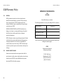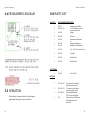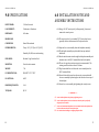
1
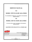
SSW-321-D -ISSUE 4.01 SSW-321-D -ISSUE 4.01 Who we are: CEECO has been engaged in the telecommunications industry for over 80 years. As a premier designer and manufacturer of both standard and custom telephone solutions, CEECO is dedicated to meeting customer’s needs. Whether the application is Emergency, Security, Weatherproof, Courtesy or Public Telephones, CEECO remains committed to delivering high quality and proven technology to this broad range of applications. In order to provide effective solutions, CEECO stands strong in its ability to understand the unique requirements of its customers and the markets they serve. This understanding has allowed CEECO to develop a family of products that offers “off-the-shelf” solutions, customized options, or OEM designs to meet unique customer or application requirements. In addition to telephone solutions, CEECO manufactures and provides telephone equipment such as telephone kits, hook switches, dials, printed circuit boards, and keypads. Whatever the application may require, CEECO is prepared to offer affordable solutions that are “Built to Last”, with customer support that lasts the life of the product! CEECO is proud to manufacture our telephones in the USA. Contact Us Service Manual For SSW-321-D -IP Voice over Internet Protocol -ACH** Handset cord length_________Inches -M Magnetic Hookswitch -CCH Coiled cord length ___________Feet 5’, 10’, or 15’ -BK Braille Keypad -PBVC Pushbutton volume control on Handset -IVC Internal Volume Control & Background Noise Reduction -C Background noise reduction on Handset -ACH* Handset Color _________________ (Red, Yellow or White) -BR Braille emergency Plate 519 S.W. Park Street Okeechobee, FL 33313 Phone: 863-357-0798 Fax: 863-357-0006 Email: [email protected] Web: www.ceeco.net Communication Equipment & Engineering Company 519 S.W. Park Street Okeechobee, FL 33313 Phone: 863-357-0798 Fax: 863-357-0006 Email: [email protected] Web: www.ceeco.net 519 S.W. Park Street Okeechobee, FL 33313 SSW-321-D -ISSUE 4.01 Table of Contents SSW-321-D -ISSUE 4.01 NOTES Important Customer Information ............................................................................1 1.0 Introduction ...............................................................................................................2 2.0 General Description ................................................................................................2 3.0 Recommended Tools & Test Equipment .......................................................2 4.0 Programming .............................................................................................................3 4.6 Programming Diagram ..........................................................................................4 5.0 Operation .....................................................................................................................4 6.0 Installation Notes & Assembly Instructions ................................................5 7.0 Testing ..........................................................................................................................6 8.0 Troubleshooting Guide ..........................................................................................7 9.0 Specifications .............................................................................................................8 10.0 Parts List ...................................................................................................................9 11.0 FCC Notice ............................................................................................................10 12.0 Repair and Return.............................................................................................11 13.0 Warranty Policy .................................................................................................12 13 SSW-321-D -ISSUE 4.01 13.0 Warranty Policy 13.1 UNDER NO CIRCUMSTANCES shall CEECO be liable for loss, damage, cost of repair, or consequential damages of any kind, which have been caused by neglect, abuse or improper operation of equipment. CEECO will repair or replace any unit during this period if found to be defective for reasons other than abuse and improper use or improper installation. It is the buyer’s responsibility to return the defective unit to the factory. CEECO will then repair or replace any defective parts and return them to the buyer free of charge. PRINTED CIRCUIT BOARDS Printed circuit boards should not be repaired in the field. If a unit is found to be faulty, replace it with another unit and return the faulty unit to CEECO for repair. Modifications by anyone other than CEECO will void the warranty. 12 IMPORTANT INFORMATION FOR CUSTOMER GENERAL CEECO guarantees its products to be free from defects in material and workmanship for a period of 365 days from the date of original purchase. CEECO's obligation under this warranty is limited to repair or replacement of any part found to be defective by CEECO. 13.2 SSW-321-D -ISSUE 4.01 Please fill in before you continue. The following information is necessary when calling CEECO for assistance. MODEL NUMBER SSW-321-D SERIAL NUMBER DATE MANUFACTURED LOCATION INSTALLED For us to better serve you, please have this information available when calling for technical support. CEECO Communication Equipment & Engineering Company 519 S.W. Park Street Okeechobee, FL. 34972 (863) 357-0798 Voice (863) 357-0006 Fax 1 SSW-321-D -ISSUE 4.01 1.0 SSW-321-D -ISSUE 4.01 INTRODUCTION The practices in this manual provide installation and maintenance information for CEECO Telephone Model SSW 321-D, which is a mini Stainless Steel Wall Telephone equipped with the ATD11 automatic dialing board. The information in this manual is subject to change without notification. For information not included in this manual, please call or write: CEECO Customer Service 519 S.W. Park Street Okeechobee, FL. 34972 (863) 357-0798 PHONE (863) 357-0006 FAX 2.0 3.0 2 GENERAL DESCRIPTION The CEECO Model SSW-321-D Mini Wall telephone is designed for special applications where a telephone must be both sturdy and attractive. It is equipped with an ATD-11 automatic tone dialer that will dial a single number of up to eleven (11) digits. The auto dialing feature is activated by hookswitch closure, when the handset is lifted. The SSW-321-D is not designed for incoming calls, but may still receive them. If a call is placed to the phone, the automatic dialer will still dial its number when the receiver is lifted off hook. RECOMMENDED TOOLS AND TEST EQUIPMENT Volt/Ohm Meter 1/4" Nut Driver Flat Blade Screw Driver Security Tool CEECO Part Number 301-037 12.0 REPAIR AND RETURN INFORMATION 12.1 WARRANTY REPAIR Any device returned requiring warranty service; repair or credit must be accompanied with a "Return Material Authorization" (RMA) Form. It must include: RMA Number, return shipping instructions, original purchase order number, serial number and special marking instructions. A tag with the trouble observed must be attached to the defective unit. This information must be inside the shipping container. 12.2 DIRECT ALL INQUIRES TO: CEECO Repair Department 519 S.W. Park Street Okeechobee, FL. 34972 (863) 357-0798 12.3 NON-WARRANTY REPAIR CEECO will repair equipment out of warranty for a set charge plus parts. The customer must pay the shipping costs both directions. 12.4 RETURN FOR CREDIT Material may be returned for credit only with prior approval. Material authorized for return is subject to a 20% restocking charge based on the manufacturer's list price. Return Material Authorization must be requested within 30 days after original shipment. Items returned for credit must be returned in their original shipping container. 11 SSW-321-D -ISSUE 4.01 11.0 11.1 FCC NOTICE FCC REGISTRATION AND REPAIR INFORMATION Your new telephone has been registered with the Federal Communication Commission (FCC) in accordance with Part 68. The FCC requires that you be advised of certain requirements involving the use of this telephone. 11.2 NOTE: Tell them: The "line" to which you will connect the telephone (your phone number) and the telephone's FCC registration number and ringer equivalence number. These numbers are listed in section 9.0. The FCC further requires that you notify your local telephone company when permanently disconnecting this telephone. It is recommended that you ground yourself to prevent ESD damage to the PCB(s). 4.1 If the number to be programmed is a (1+) call, position the J1 green mini-jumper on the "1+" position, which will cause the digit "1" to be dialed in front of the other digits. If the number to be programmed is a local call, position the J1 green minijumper on the "P" position, which is also the farthest right position. If you have difficulty locating the J1 green minijumper, it is the first jumper position you will see just below the right hand corner of the A-K main matrix board, which contains ten green mini-jumpers. 4.2 If a 3 digit area code is to be dialed, position the J3 green minijumper on the "11" position. If the number being dialed is within the same area code, position the J3 green mini-jumper on the "8" position. The J3 green mini-jumper is located just below the J1 jumper. It is the second green mini-jumper you will see below the right hand corner of the A-K main matrix board. 4.3 Set each of the 10 green mini-jumpers on the A-K main matrix board to correspond to the 10 digits of the number to be dialed. The last 3 digits will be ignored if the J3 jumper is on "8". 4.4 Be sure each green mini-jumper is properly positioned to make good contact and dial the intended number. 4.5 Temporarily remove the J2 jumper. As accurately as possible, measure the time delay between the moment the handset is lifted and the moment the phone receives dial tone. Try it several times. If this time is consistently 1 second or less, position the J2 jumper on the "1" position to set the delay before dialing to 1 1/2 to 2 seconds. Otherwise position the J2 jumper on the "3" position to set the delay before dialing to 3 to 4 seconds. The J2 mini-jumper is the lone green mini-jumper located farthest from the right hand corner of the A-K main matrix board. NOTIFICATION TO THE TELEPHONE COMPANY Before connecting this telephone, the FCC requires that you notify your local telephone company business office. The number is in the front of your phone book. 10 4.0 PROGRAMMING CONNECTION WITH THE NATIONWIDE TELEPHONE NETWORK The FCC requires that you connect this telephone to the Nationwide Telephone Network through a registered jack provided by the telephone company in your area. This jack is a modular outlet, which you can order from your local telephone company. 11.3 SSW-321-D -ISSUE 4.01 3 SSW-321-D -ISSUE 4.01 4.6 PROGRAMMING DIAGRAM SSW-321-D -ISSUE 4.01 10.0 PARTS LIST QUANTITY PART NUMBER DESCRIPTION 1 1 ATD-11 301-106-32-1 Automatic Tone Dialer 32” ACH Handset w/steel Lanyard and Swivel Ringer 1 401-009 1 1 301-009 301-528 1 1 301-592 321-015 Network Mechanical Hookswitch or Magnetic Hookswitch Stainless Steel Backplate 1 321-016 1/4 - 20 x 3/4 Security Screw 1 301-052 Grommet 1 301-018 Modular Cord 1 301-054 Modular Jack 301-037 Security Tool ACCESSORIES: 1 OPTIONS: 5.0 OPERATION Lift the handset. Automatic dialer will call the number programmed. Normal phone operation follows. 4 1 301-106-18-1 1 301-106-12-1 1 301-106-XX 1 -IVC 18” armored cord handset with lanyard and swivel 12” armored cord handset with lanyard and swivel Other Length Handsets “XX” denotes cord length Volume Control Push Button and background noise reduction 9 SSW-321-D -ISSUE 4.01 SSW-321-D -ISSUE 4.01 9.0 SPECIFICATIONS INPUT POWER: C.O. Line Powered LOOP CURRENT: 23mA min to 80mA max IMPEDANCE: 600 ohms HEARING AID COMPATIBLE: Meets EIA standards ENVIRONMENTAL: Temp. -30C (-22F) to 60C (140F) Humidity 0%-90% non-condensating ENCLOSURE: Brushed 16 ga. Stainless Steel MOUNTING: Vertical surface mount WEIGHT: 7 lb. FCC REGISTRATION: BW-88T7-13717-TE-T UL LISTED NO.: 6OF5 RINGER EQUIVALENCY: 0.4A TYPE JACK: RJ11C 6.0 INSTALLATION NOTES AND ASSEMBLY INSTRUCTIONS 6.1. Using a 301-037 security tool (sold separately), loosen and remove the security screw. 6.2. The security tool is for a standard 5/32" button head screw generally used on the framework of the phone booths. 6.3. Separate the cover assembly from the backplate assembly. 6.4. The backplate assembly may be installed on any standard backboard 6.5. Run the inside station wire through the backplate assembly and terminate on to the RJ11C terminal block on the backplate. 6.6. The use of a gas tube station protector is recommended. The station ground should not exceed 50 ohms. 6.7. Plug the modular line cord from the cover assembly into the RJ11C terminal block. 6.8. Dress the line cable away from the security screw and install the cover assembly by inserting the tabs into the slots on top of the backplate. 6.9. Secure the cover assembly by tightening the security screw. *****WARNING***** A. Never install telephone wiring during a lightning storm. B. Never install telephone jacks in wet locations unless the jack is specifically designed for wet locations. C. Never touch uninsulated telephone wires or terminals unless the telephone line has been disconnected at the network interface. D. Use caution when installing or modifying telephone lines. 8 5 SSW-321-D -ISSUE 4.01 7.0 TESTING SSW-321-D -ISSUE 4.01 8.0 TROUBLESHOOTING GUIDE Always visually check the phone for loose or shorted wires, damaged terminals or damaged parts. 7.1 Program the phone according to section 3.0. PROBLEM: NO DIAL TONE POSSIBLE CAUSE: 7.2 Lift the handset. 7.3 Phone waits one and one half to four seconds (depending on the position of J2. Section 3.5). The programmed number is automatically dialed. LINE CORD CONNECTOR RJ11C CONNECTOR NETWORK HANDSET ATD-11A BOARD PROBLEM: DIAL TONE IS DISTORTED POSSIBLE CAUSE: 7.4 The transmitter is muted while the phone is dialing. NETWORK HANDSET PROBLEM: TRANSMITTER DOES NOT TURN ON 7.5 Incoming calls are not recommended but if a call is placed in to the phone and the handset is lifted there is a one and one half to four second delay (depending on the position of J2. Section 3.5), the programmed number is dialed, and then a normal phone conversation can take place. POSSIBLE CAUSE: HANDSET NETWORK PROBLEM: PHONE DOESN'T DIAL PROGRAMMED NUMBER POSSIBLE CAUSE: ATD-11A BOARD PROGRAMMING SWITCH MATRIX SET WRONG JUMPER IN WRONG POSITION PROBLEM: RINGER DOES NOT OPERATE POSSIBLE CAUSE: RINGER NETWORK 6 7 SSW-321-D -ISSUE 4.01 7.0 TESTING SSW-321-D -ISSUE 4.01 8.0 TROUBLESHOOTING GUIDE Always visually check the phone for loose or shorted wires, damaged terminals or damaged parts. 7.1 Program the phone according to section 3.0. PROBLEM: NO DIAL TONE POSSIBLE CAUSE: 7.2 Lift the handset. 7.3 Phone waits one and one half to four seconds (depending on the position of J2. Section 3.5). The programmed number is automatically dialed. LINE CORD CONNECTOR RJ11C CONNECTOR NETWORK HANDSET ATD-11A BOARD PROBLEM: DIAL TONE IS DISTORTED POSSIBLE CAUSE: 7.4 The transmitter is muted while the phone is dialing. NETWORK HANDSET PROBLEM: TRANSMITTER DOES NOT TURN ON 7.5 Incoming calls are not recommended but if a call is placed in to the phone and the handset is lifted there is a one and one half to four second delay (depending on the position of J2. Section 3.5), the programmed number is dialed, and then a normal phone conversation can take place. POSSIBLE CAUSE: HANDSET NETWORK PROBLEM: PHONE DOESN'T DIAL PROGRAMMED NUMBER POSSIBLE CAUSE: ATD-11A BOARD PROGRAMMING SWITCH MATRIX SET WRONG JUMPER IN WRONG POSITION PROBLEM: RINGER DOES NOT OPERATE POSSIBLE CAUSE: RINGER NETWORK 6 7 SSW-321-D -ISSUE 4.01 SSW-321-D -ISSUE 4.01 9.0 SPECIFICATIONS INPUT POWER: C.O. Line Powered LOOP CURRENT: 23mA min to 80mA max IMPEDANCE: 600 ohms HEARING AID COMPATIBLE: Meets EIA standards ENVIRONMENTAL: Temp. -30C (-22F) to 60C (140F) Humidity 0%-90% non-condensating ENCLOSURE: Brushed 16 ga. Stainless Steel MOUNTING: Vertical surface mount WEIGHT: 7 lb. FCC REGISTRATION: BW-88T7-13717-TE-T UL LISTED NO.: 6OF5 RINGER EQUIVALENCY: 0.4A TYPE JACK: RJ11C 6.0 INSTALLATION NOTES AND ASSEMBLY INSTRUCTIONS 6.1. Using a 301-037 security tool (sold separately), loosen and remove the security screw. 6.2. The security tool is for a standard 5/32" button head screw generally used on the framework of the phone booths. 6.3. Separate the cover assembly from the backplate assembly. 6.4. The backplate assembly may be installed on any standard backboard 6.5. Run the inside station wire through the backplate assembly and terminate on to the RJ11C terminal block on the backplate. 6.6. The use of a gas tube station protector is recommended. The station ground should not exceed 50 ohms. 6.7. Plug the modular line cord from the cover assembly into the RJ11C terminal block. 6.8. Dress the line cable away from the security screw and install the cover assembly by inserting the tabs into the slots on top of the backplate. 6.9. Secure the cover assembly by tightening the security screw. *****WARNING***** A. Never install telephone wiring during a lightning storm. B. Never install telephone jacks in wet locations unless the jack is specifically designed for wet locations. C. Never touch uninsulated telephone wires or terminals unless the telephone line has been disconnected at the network interface. D. Use caution when installing or modifying telephone lines. 8 5 SSW-321-D -ISSUE 4.01 4.6 PROGRAMMING DIAGRAM SSW-321-D -ISSUE 4.01 10.0 PARTS LIST QUANTITY PART NUMBER DESCRIPTION 1 1 ATD-11 301-106-32-1 Automatic Tone Dialer 32” ACH Handset w/steel Lanyard and Swivel Ringer 1 401-009 1 1 301-009 301-528 1 1 301-592 321-015 Network Mechanical Hookswitch or Magnetic Hookswitch Stainless Steel Backplate 1 321-016 1/4 - 20 x 3/4 Security Screw 1 301-052 Grommet 1 301-018 Modular Cord 1 301-054 Modular Jack 301-037 Security Tool ACCESSORIES: 1 OPTIONS: 5.0 OPERATION Lift the handset. Automatic dialer will call the number programmed. Normal phone operation follows. 4 1 301-106-18-1 1 301-106-12-1 1 301-106-XX 1 -IVC 18” armored cord handset with lanyard and swivel 12” armored cord handset with lanyard and swivel Other Length Handsets “XX” denotes cord length Volume Control Push Button and background noise reduction 9 SSW-321-D -ISSUE 4.01 11.0 11.1 FCC NOTICE FCC REGISTRATION AND REPAIR INFORMATION Your new telephone has been registered with the Federal Communication Commission (FCC) in accordance with Part 68. The FCC requires that you be advised of certain requirements involving the use of this telephone. 11.2 NOTE: Tell them: The "line" to which you will connect the telephone (your phone number) and the telephone's FCC registration number and ringer equivalence number. These numbers are listed in section 9.0. The FCC further requires that you notify your local telephone company when permanently disconnecting this telephone. It is recommended that you ground yourself to prevent ESD damage to the PCB(s). 4.1 If the number to be programmed is a (1+) call, position the J1 green mini-jumper on the "1+" position, which will cause the digit "1" to be dialed in front of the other digits. If the number to be programmed is a local call, position the J1 green minijumper on the "P" position, which is also the farthest right position. If you have difficulty locating the J1 green minijumper, it is the first jumper position you will see just below the right hand corner of the A-K main matrix board, which contains ten green mini-jumpers. 4.2 If a 3 digit area code is to be dialed, position the J3 green minijumper on the "11" position. If the number being dialed is within the same area code, position the J3 green mini-jumper on the "8" position. The J3 green mini-jumper is located just below the J1 jumper. It is the second green mini-jumper you will see below the right hand corner of the A-K main matrix board. 4.3 Set each of the 10 green mini-jumpers on the A-K main matrix board to correspond to the 10 digits of the number to be dialed. The last 3 digits will be ignored if the J3 jumper is on "8". 4.4 Be sure each green mini-jumper is properly positioned to make good contact and dial the intended number. 4.5 Temporarily remove the J2 jumper. As accurately as possible, measure the time delay between the moment the handset is lifted and the moment the phone receives dial tone. Try it several times. If this time is consistently 1 second or less, position the J2 jumper on the "1" position to set the delay before dialing to 1 1/2 to 2 seconds. Otherwise position the J2 jumper on the "3" position to set the delay before dialing to 3 to 4 seconds. The J2 mini-jumper is the lone green mini-jumper located farthest from the right hand corner of the A-K main matrix board. NOTIFICATION TO THE TELEPHONE COMPANY Before connecting this telephone, the FCC requires that you notify your local telephone company business office. The number is in the front of your phone book. 10 4.0 PROGRAMMING CONNECTION WITH THE NATIONWIDE TELEPHONE NETWORK The FCC requires that you connect this telephone to the Nationwide Telephone Network through a registered jack provided by the telephone company in your area. This jack is a modular outlet, which you can order from your local telephone company. 11.3 SSW-321-D -ISSUE 4.01 3 SSW-321-D -ISSUE 4.01 1.0 SSW-321-D -ISSUE 4.01 INTRODUCTION The practices in this manual provide installation and maintenance information for CEECO Telephone Model SSW 321-D, which is a mini Stainless Steel Wall Telephone equipped with the ATD11 automatic dialing board. The information in this manual is subject to change without notification. For information not included in this manual, please call or write: CEECO Customer Service 519 S.W. Park Street Okeechobee, FL. 34972 (863) 357-0798 PHONE (863) 357-0006 FAX 2.0 3.0 2 GENERAL DESCRIPTION The CEECO Model SSW-321-D Mini Wall telephone is designed for special applications where a telephone must be both sturdy and attractive. It is equipped with an ATD-11 automatic tone dialer that will dial a single number of up to eleven (11) digits. The auto dialing feature is activated by hookswitch closure, when the handset is lifted. The SSW-321-D is not designed for incoming calls, but may still receive them. If a call is placed to the phone, the automatic dialer will still dial its number when the receiver is lifted off hook. RECOMMENDED TOOLS AND TEST EQUIPMENT Volt/Ohm Meter 1/4" Nut Driver Flat Blade Screw Driver Security Tool CEECO Part Number 301-037 12.0 REPAIR AND RETURN INFORMATION 12.1 WARRANTY REPAIR Any device returned requiring warranty service; repair or credit must be accompanied with a "Return Material Authorization" (RMA) Form. It must include: RMA Number, return shipping instructions, original purchase order number, serial number and special marking instructions. A tag with the trouble observed must be attached to the defective unit. This information must be inside the shipping container. 12.2 DIRECT ALL INQUIRES TO: CEECO Repair Department 519 S.W. Park Street Okeechobee, FL. 34972 (863) 357-0798 12.3 NON-WARRANTY REPAIR CEECO will repair equipment out of warranty for a set charge plus parts. The customer must pay the shipping costs both directions. 12.4 RETURN FOR CREDIT Material may be returned for credit only with prior approval. Material authorized for return is subject to a 20% restocking charge based on the manufacturer's list price. Return Material Authorization must be requested within 30 days after original shipment. Items returned for credit must be returned in their original shipping container. 11 SSW-321-D -ISSUE 4.01 13.0 Warranty Policy 13.1 UNDER NO CIRCUMSTANCES shall CEECO be liable for loss, damage, cost of repair, or consequential damages of any kind, which have been caused by neglect, abuse or improper operation of equipment. CEECO will repair or replace any unit during this period if found to be defective for reasons other than abuse and improper use or improper installation. It is the buyer’s responsibility to return the defective unit to the factory. CEECO will then repair or replace any defective parts and return them to the buyer free of charge. PRINTED CIRCUIT BOARDS Printed circuit boards should not be repaired in the field. If a unit is found to be faulty, replace it with another unit and return the faulty unit to CEECO for repair. Modifications by anyone other than CEECO will void the warranty. 12 IMPORTANT INFORMATION FOR CUSTOMER GENERAL CEECO guarantees its products to be free from defects in material and workmanship for a period of 365 days from the date of original purchase. CEECO's obligation under this warranty is limited to repair or replacement of any part found to be defective by CEECO. 13.2 SSW-321-D -ISSUE 4.01 Please fill in before you continue. The following information is necessary when calling CEECO for assistance. MODEL NUMBER SERIAL NUMBER DATE MANUFACTURED LOCATION INSTALLED For us to better serve you, please have this information available when calling for technical support. CEECO Communication Equipment & Engineering Company 519 S.W. Park Street Okeechobee, FL. 34972 (863) 357-0798 Voice (863) 357-0006 Fax 1 SSW-321-D -ISSUE 4.01 Table of Contents SSW-321-D -ISSUE 4.01 NOTES Important Customer Information ............................................................................1 1.0 Introduction ...............................................................................................................2 2.0 General Description ................................................................................................2 3.0 Recommended Tools & Test Equipment .......................................................2 4.0 Programming .............................................................................................................3 4.6 Programming Diagram ..........................................................................................4 5.0 Operation .....................................................................................................................4 6.0 Installation Notes & Assembly Instructions ................................................5 7.0 Testing ..........................................................................................................................6 8.0 Troubleshooting Guide ..........................................................................................7 9.0 Specifications .............................................................................................................8 10.0 Parts List ...................................................................................................................9 11.0 FCC Notice ............................................................................................................10 12.0 Repair and Return.............................................................................................11 13.0 Warranty Policy .................................................................................................12 13 SSW-321-D -ISSUE 4.01 SSW-321-D -ISSUE 4.01 Who we are: CEECO has been engaged in the telecommunications industry for over 80 years. As a premier designer and manufacturer of both standard and custom telephone solutions, CEECO is dedicated to meeting customer’s needs. Whether the application is Emergency, Security, Weatherproof, Courtesy or Public Telephones, CEECO remains committed to delivering high quality and proven technology to this broad range of applications. In order to provide effective solutions, CEECO stands strong in its ability to understand the unique requirements of its customers and the markets they serve. This understanding has allowed CEECO to develop a family of products that offers “off-the-shelf” solutions, customized options, or OEM designs to meet unique customer or application requirements. In addition to telephone solutions, CEECO manufactures and provides telephone equipment such as telephone kits, hook switches, dials, printed circuit boards, and keypads. Whatever the application may require, CEECO is prepared to offer affordable solutions that are “Built to Last”, with customer support that lasts the life of the product! CEECO is proud to manufacture our telephones in the USA. Contact Us Service Manual For -IP Voice over Internet Protocol -ACH** Handset cord length_________Inches -M Magnetic Hookswitch -CCH Coiled cord length ___________Feet 5’, 10’, or 15’ -BK Braille Keypad -PBVC Pushbutton volume control on Handset -IVC Internal Volume Control & Background Noise Reduction -C Background noise reduction on Handset -ACH* Handset Color _________________ (Red, Yellow or White) -BR Braille emergency Plate 519 S.W. Park Street Okeechobee, FL 33313 Phone: 863-357-0798 Fax: 863-357-0006 Email: [email protected] Web: www.ceeco.net Communication Equipment & Engineering Company 519 S.W. Park Street Okeechobee, FL 33313 Phone: 863-357-0798 Fax: 863-357-0006 Email: [email protected] Web: www.ceeco.net 519 S.W. Park Street Okeechobee, FL 33313