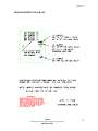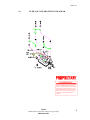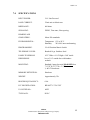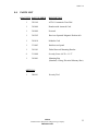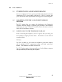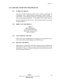
1
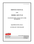
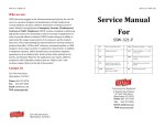
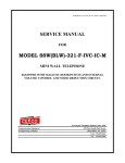
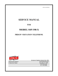
SSP-351-D-M-ATD11-ISSUE5.0
SERVICE MANUAL
FOR
MODEL SSP-351-D-M
STAINLESS STEEL PANEL
TELEPHONE
EQUIPPED WITH ATD-11 BOARD
Serving the Telephone Industry Since 1930
Communication Equipment
& Engineering Company
519 West South Park Street
Okeechobee, Florida 34972
Voice: 863-357-0798
Fax:
863-357-0006
ISSUE 4.0
IMPORTANT INFORMATION
FOR
CUSTOMER
Please fill in before you continue.
The following information is necessary when calling CEECO for assistance.
MODEL NUMBER
MODEL SSP-351-D-M STAINLESS
STEEL PANEL TELEPHONE.
SERIAL NUMBER
DATE MANUFACTURED
LOCATION INSTALLED
For us to better serve you, please have this information available when calling for
technical support.
CEECO
Communication Equipment and Engineering Company
519 West South Park Street
Okeechobee, Florida 34972
(863) 357-0798 Voice
(863) 357-0006 Fax
CEECO
Communication Equipment & Engineering Company
PROPRIETARY
2
ISSUE 4.0
TABLE OF CONTENTS
SECTION
PAGE
1.0
INTRODUCTION................................................................................................. 4
2.0
GENERAL DESCRIPTION ................................................................................ 4
3.0
PROGRAMMING ................................................................................................ 5
PROGRAMMING DIAGRAM:PROGRAMMING CONTINUED…............ 6
PROGRAMMING CONTINUED…................................................................... 7
4.0
TESTING/OPERATION ..................................................................................... 7
5.0
RECOMMENDED TOOLS AND TEST EQUIPMENT .................................. 7
6.0
INSTALLATION NOTES AND ASSEMBLY INSTRUCTIONS ................... 8
7.0
SPECIFICATIONS............................................................................................. 10
8.0
PARTS LIST ....................................................................................................... 11
9.0
FCC NOTICE...................................................................................................... 12
10.0
REPAIR AND RETURN INFORMATION..................................................... 13
11.0
WARRANTY POLICY ...................................................................................... 14
CEECO
Communication Equipment & Engineering Company
PROPRIETARY
3
ISSUE 4.0
1.0
INTRODUCTION
The practices in this manual provide installation and maintenance information for
Model SSP-351-D-M Stainless Steel Panel Telephone.
The information in this manual is subject to change without notification.
For information not included in this manual, please call or write:
CEECO
Customer Service
519 West South Park Street
Okeechobee, Florida 34972
(863) 357-0798
(863) 357-0006 FAX
2.0
GENERAL DESCRIPTION
The CEECO Model SSP-351-D-M Stainless Steel Panel Telephone is an
automatic tone dialing phone designed for special applications where a telephone
must fit into tight space restrictions within a wall. It mounts by way of a standard,
4-gang, electrical masonry box. It is equipped with an ATD-11 automatic tone
dialer that will dial a single number of up to eleven (11) digits. The automatic
dialing feature is activated by hookswitch closure.
The SSP-351-D-M may receive calls, but the auto-dialer will still send out the
digits upon the initial answer. A normal conversation may take place thereafter.
The SSP-351-D-M incorporates a receiver-operated magnetic hookswitch that
helps to seal the unit against water and foreign matter penetration, as well as
eliminates moving parts for long-life operation under harsh conditions.
CEECO
Communication Equipment & Engineering Company
PROPRIETARY
4
ISSUE 4.0
3.0
PROGRAMMING
NOTE:
It is recommended that you ground yourself to prevent ESD
damage to the PCB(s). This can be done through the use of an
electrostatic bracelet or other such device. In the absence of any
such device, it might suffice to simply touch a conduit or other
grounded pipe or object to dissipate any built up static electricity.
3.1
Please refer to the diagram on the next page for mini-jumper location
and positioning. Programming is accomplished by position plastic
hardware mini-jumpers in the proper positions for the desired calling
pattern. The mini-jumpers are designed to bridge pairs of copper pins to
activate the desired dialing pattern.
3.2
Locate the ATD-11 Automatic Dialer.
3.3
If the number to be programmed is a (1+) call, position the J1 mini-jumper
on the "1+" position, bridging the left and center copper pins. This will
cause the digit "1" to be dialed in front of the other programmed digits. If
the number to be programmed is a local call, position the J1 mini-jumper
on the "B" position, bridging the center and right copper pins.
3.4
If a 3 digit area code is to be dialed, the J3 mini-jumper must be set to the
"11" position, bridging the center and left copper pins. If the number
being dialed does not require the area code, position the J3 mini-jumper on
the "8" position, bridging the center and right copper pins.
3.5
Set each mini-jumper on the A-K matrix board to correspond to the digits
of the number to be dialed. Beginning with column “A” at the top,
position the plastic mini-jumper to bridge the pair of copper pins
corresponding to the desired digit (1-0). Proceed in the same manner,
from left to right, until all desired digits are programmed. Do not skip any
columns, as the digits must be represented in an unbroken string. Any
unused mini-jumpers must be removed from the board to ensure proper
dialing. Do not discard the unused jumpers, as they may be needed for
future use. It is recommended that they be taped or otherwise secured
somewhere nearby, within the device.
3.6
Be sure each mini-jumper is properly positioned to make good contact and
dial the intended number.
CEECO
Communication Equipment & Engineering Company
PROPRIETARY
5
ISSUE 4.0
PROGRAMMING DIAGRAM:
CEECO
Communication Equipment & Engineering Company
PROPRIETARY
6
ISSUE 4.0
PROGRAMMING CONTINUED…
3.7 In most installations, the J2 mini-jumper will remain in the “1” position,
bridging the center and left copper pins. If dial tone delivery is delayed by
more than one second; however, then J2 will have to be set in the “3” position.
A simple test would be as follows: with the telephone line cord connected to
the intended telephone line, temporarily remove the J2 mini-jumper. As
accurately as possible, measure the time delay between the moment the
handset is lifted and the moment the phone receives dial tone. Try it several
times. If this time is consistently 1 second or less, position the J2 jumper on
the "1" position. Otherwise position the J2 jumper on the "3" position to set
the delay before dialing to 3 to 4 seconds.
4.0
5.0
TESTING/OPERATION
4.1
Program the phone according to section 3.0
4.2
Lift the handset. Phone waits one and one half to four seconds (depending
on the position of J2 per Section 3.7). The programmed number is
automatically dialed.
4.3
The transmitter is muted while the phone is dialing.
4.4
Incoming calls are not able to be detected, due to the lack of a ringer.
RECOMMENDED TOOLS AND TEST EQUIPMENT
Volt/Ohm Meter
1/4" Nut Driver
Flat Blade Screw Driver
Security Tool, CEECO Part Number 301-064
CEECO
Communication Equipment & Engineering Company
PROPRIETARY
7
ISSUE 4.0
6.0
INSTALLATION NOTES AND ASSEMBLY INSTRUCTIONS
6.1
Using a 301-064 security tool (sold separately) loosen and remove the security
screws. The security tool is for a standard 5/32" button head screw generally used
on the framework of the phone booths.
6.2
Carefully separate the faceplate assembly from the mounting box by gently
pulling the faceplate forward.
6.3
Determine and remove the desired knock out hole for running the telephone wire,
and mount the masonry box as needed.
6.4
Run the telephone wire into the box and terminate on the provided RJ11C
modular jack, as depicted on the following page. The CEECO-provided modular
jack must be used, as it contains required over-voltage protection circuitry.
6.5
The use of a gas tube or carbon station protector is recommended. The station
ground should not exceed 50 ohms.
6.6
Plug the modular line cord from the faceplate assembly into the RJ11C terminal
block.
6.7
Dress the line cable and modular jack away from the security screws and seat the
faceplate into the housing enclosure.
6.8
Secure the faceplate assembly by tightening the security screws.
WARNING
A. Never install telephone wiring during a lightning storm.
B. Never install telephone jacks in wet locations unless the jack is
specifically designed for wet locations.
C. Never touch uninsulated telephone wires or terminals unless the
telephone line has been disconnected at the network interface.
D. Use caution when installing or modifying telephone lines.
CEECO
Communication Equipment & Engineering Company
PROPRIETARY
8
ISSUE 4.0
6.9
OVER-VOLTAGE PROTECTION DIAGRAM
CONFIDENTIAL
This drawing and all information contained
therein is confidential and is the exclusive
property of CEECO and may not be copied,
reproduced or disclosed to anyone, in any
manner whatsoever, or used for any purpose
other than for which it is provided to you,
without the prior written permission of
CEECO.
CEECO
Communication Equipment & Engineering Company
PROPRIETARY
9
ISSUE 4.0
7.0
SPECIFICATIONS
INPUT POWER:
C.O. Line Powered
LOOP CURRENT:
23mA min to 80mA max
IMPEDANCE:
600 ohms
SIGNALING:
DTMF, 70ms tone, 50ms spacing
HEARING AID
COMPATIBLE:
Meets EIA standards
ENVIRONMENTAL:
Temperature 0°C to 50°C
Humidity
20%-90% non-condensating
PROGRAMMING:
Via 10-Position Matrix Switch
TELEPHONE COVER:
Brushed 16 ga. Stainless Steel
PANEL TELEPHONE
DIMENSIONS
4.55" Wide x 8 1/4" High x 2.60" inside
box x 3.10" outside box with handset
on hook
MOUNTING:
Standard 4 gang electrical MASONRY box
7 13/32”H x 3 ¾”W x 3 ½”D
½ &3/4” Knockouts.
MEMORY RETENTION:
Hardware
WEIGHT:
Approximately 3 lb.
RINGER EQUIVALENCY:
0.4A
FCC REGISTRATION:
BW-88T7-13716-TE-T
UL LISTED NO.:
6OF5
TYPE JACK:
RJ11C
CEECO
Communication Equipment & Engineering Company
PROPRIETARY
10
ISSUE 4.0
8.0
PARTS LIST
QUANTITY PART NUMBER
DESCRIPTION
1
350-169
ATD-11 Automatic Tone Dial
1
301-004
Handset with Armored Cord
1
301-009
Network
1
301-592
Receiver-Operated Magnetic Hookswitch
1
301-018
Modular Cord
1
331-003
Stainless steel panel
1
310-101
Dialer/Network Mounting Bracket
4
311-008
Security Screw #6-32 x 1 1/2”
1
301-001
Mounting Box
(Standard, 4-Gang, Electrical Masonry Box)
OPTIONS:
1
30l-064
Security Tool
CEECO
Communication Equipment & Engineering Company
PROPRIETARY
11
ISSUE 4.0
9.0
FCC NOTICE
9.1
FCC REGISTRATION AND REPAIR INFORMATION
Your new telephone has been registered with the Federal Communication
Commission (FCC) in accordance with Part 68. The FCC requires that
you be advised of certain requirements involving the use of this telephone.
9.2
CONNECTION WITH THE NATIONWIDE TELEPHONE
NETWORK
The FCC requires that you connect this telephone to the Nationwide
Telephone Network through a registered jack provided by the telephone
company in your area. This jack is a modular outlet which you can order
from your local telephone company.
9.3
NOTIFICATION TO THE TELEPHONE COMPANY
Before connecting this telephone, the FCC requires that you notify your
local telephone company business office. The number is in the front of
your phone book.
Tell them:
The "line" to which you will connect the telephone (your phone number)
and the telephone's FCC registration number and ringer equivalence
number. These numbers are listed in Section 9.0.
The FCC further requires that you notify your local telephone company
when permanently disconnecting this telephone.
CEECO
Communication Equipment & Engineering Company
PROPRIETARY
12
ISSUE 4.0
10.0 REPAIR AND RETURN INFORMATION
10.1
WARRANTY REPAIR
Any device returned requiring warranty service; repair or credit must be
accompanied with a "Return Material Authorization" (RMA) FORM. It
must include: return shipping instructions, original purchase order number
and special marking instruction. A description of the trouble observed
must be attached to the defective unit. This information must be inside the
shipping container.
10.2
DIRECT ALL INQUIRES TO:
CEECO
Repair Department
519 West South Park Street
Okeechobee, Florida 34972
(863) 357-0798
10.3
NON-WARRANTY REPAIR
CEECO will repair equipment out of warranty for a set charge plus parts.
The customer must pay the shipping costs both directions.
10.4
RETURN FOR CREDIT
Material may be returned for credit only with prior approval. Material not
authorized for return is subject to a 20% restocking charge based on the
manufacturer’s list price. Return RMA must be requested no later than 30
days after original shipment.
CEECO
Communication Equipment & Engineering Company
PROPRIETARY
13
ISSUE 4.0
11.0 WARRANTY POLICY
11.1
GENERAL
CEECO products are guaranteed to be free of defects in material and
workmanship for a period of 365 days from the date of original purchase.
CEECO's obligation under this warranty is limited to repair or
replacement of any part found to be defective by CEECO. Under no
circumstances shall CEECO be liable for loss, damage, cost of repair or
consequential damages of any kind which have been caused by neglect,
abuse, acts of God or improper operation of equipment.
CEECO will repair or replace any unit during this period if found to be
defective for reasons other than abuse and improper use or improper
installation. It is the buyer’s responsibility to return the defective unit to
the factory. CEECO will then repair or replace any defective parts and
return them to the buyer free of charge.
11.2
PRINTED CIRCUIT BOARDS
Printed circuit boards should not be field repaired. If a unit is found to be
faulty, replace it with another unit and return the faulty unit to CEECO for
repair. Modifications by any one other than CEECO will void the
warranty.
CEECO
Communication Equipment & Engineering Company
PROPRIETARY
14