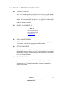
1
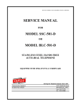
SSP-571-D (FORMERLY 579)-ADA-SPK1.07UNVLADA-ISSUE4.0
SERVICE MANUAL
FOR
MODEL SSP-571-D
(FORMERLY MODEL SSP-579-D)
HANDS FREE PANEL TELEPHONE
EQUIPPED WITH SPK1.07 UNVLADA FIRMWARE
WITH OPTIONAL ADA FEATURE
Communication Equipment
& Engineering Company
Serving the Telephone Industry Since 1930
519 W South Park Street
Okeechobee, FL 34972
Voice: 863-357-0798
Fax: 863-357-0006
ISSUE 4.0
IMPORTANT INFORMATION
FOR
CUSTOMER
Please fill in before you continue.
The following information is necessary when calling CEECO for assistance.
MODEL NUMBER
MODEL SSP-571-D-ADA EQUIPPED
WITH SPK1.07UNVLADA FIRMWARE
SERIAL NUMBER
DATE MANUFACTURED
LOCATION INSTALLED
For us to better serve you, please have this information available when calling for
technical support.
CEECO
Communication Equipment & Engineering Company
519 W South Park Street
Okeechobee, FL 34972
863-357-0798- telephone
863-357-0006- facsimile
[email protected]
www.ceeco.net
CEECO
Communication Equipment & Engineering Company
PROPRIETARY
2
ISSUE 4.0
TABLE OF CONTENTS
SECTION
PAGE
1.0
INTRODUCTION................................................................................................... 4
2.0
GENERAL............................................................................................................... 4
3.0
PROGRAMMING .................................................................................................. 5
PROGRAMMING CONTINUED…..................................................................... 7
4.0
TESTING/OPERATION ....................................................................................... 8
5.0
RECOMMENDED TOOLS AND TEST EQUIPMENT .................................... 8
6.0
INSTALLATION NOTES AND ASSEMBLY INSTRUCTIONS ..................... 8
7.0
SPECIFICATIONS............................................................................................... 10
8.0
PARTS LIST ......................................................................................................... 11
9.0
FCC NOTICE........................................................................................................ 12
10.0 REPAIR AND RETURN INFORMATION ....................................................... 13
11.0 WARRANTY POLICY ........................................................................................ 14
12.0 DIAGRAM............................................................................................................. 15
CEECO
Communication Equipment & Engineering Company
PROPRIETARY
3
ISSUE 4.0
1.0
INTRODUCTION
The practices in this manual provide installation and maintenance information for
the CEECO Model SSP 571-D Telephone.
The information in this manual is subject to change without notification.
For information not included in this manual, please call or write:
CEECO
Customer Service
519 W South Park Street
Okeechobee, FL 34972
863-357-0798- telephone
863-357-0006- facsimile
[email protected]
www.ceeco.net
2.0
GENERAL
2.1
The CEECO Model SSP 571-D Hands free telephone is a sturdy, vandal
resistant, Stainless Steel Panel Speakerphone. Instead of a hookswitch and
handset, the SSP 571-D has a Press to start/Press to stop (CALL) button
for the initiation and termination of phone calls.
2.2
The microphone is muted during periods of dial tone to help guard against
the use of hand held dialers.
2.3
Incoming calls may be allowed or blocked depending on the
programming.
2.4
Programming is accomplished via a separately supplied external DTMF
keypad.
2.5
The phone has an optional Braille emergency plate and an optional LED,
which gives a visual indication of the call progress. The LED lights red
when the phone is “off hook”, flashes red and green when ringing, and
turns steady green when the call is answered.
CEECO
Communication Equipment & Engineering Company
PROPRIETARY
4
ISSUE 4.0
3.0
PROGRAMMING
NOTE:
It is recommended that you ground yourself to prevent ESD
Damage to the PCB(s).
3.1
Connect the telephone to a working telephone line or a DTMF test set
before programming.
3.2
Locate the multicolor ribbon cable, extending from the Printed Circuit
Board, with a white connector hanging loosely. Locate the programming
keypad (provided separately), which has the mating end of the white
connector attached to it. Connect the keypad to the ribbon cable, by way
of the two connectors.
3.3
Move the mini-jumpers (located on the CEECO-SPK Printed Circuit
Board) to the "ON" position, as depicted on the last page of this manual.
3.4
Press the CALL button and wait for dial tone before programming any
digits.
3.5
It is important to be slow and deliberate when pressing the keys of the
programming keypad. A missed or partial tone could result in improper
programming.
NOTE: Once the “#" (pound) key has been entered you may get an
operator recording or a fast busy, please disregard and continue
programming.
3.6
Press the CALL button located on the front of the phone and utilize the
programming keypad to enter:
#97 #18# #19#
3.7
Enter # 0 0 followed by a series of ten (10) Digits as selected from the
options on the following page. By entering 0 thru 9 into each of the 10
digits, the phone is customized for the particular installation. A selection
for all ten Digits must be entered in order for the phone to operate
properly.
CEECO
Communication Equipment & Engineering Company
PROPRIETARY
5
ISSUE 4.0
PROGRAMMING CONTINUED…
Digit 1:
0 Always 0 for this model.
Digit 2:
0 No incoming calls allowed.
1 Incoming calls allowed.
Digit 3:
0 No Conversation Time-Out.
1-9 Minutes Conversation Time-Out.
Digit 4:
0 Always 0 for this model.
Digit 5:
0 Always 0 for this model.
Digit 6:
0 No ADA Feature.
9 Activate ADA Feature (9 must be entered to activate the ADA LED light)
Digit 7:
0 Always 0 for this model
Digit 8: (PBX Access – see section 3.9)
0 Do not dial PBX access number stored in Location #l8.
1 Dial PBX access number stored in Location #18.
Digit 9:
0 Always 0 for this model.
Digit 10:
0 No Wink Detect.
1-9 Length of the Wink (l = 50ms incremental to 450ms – entering a 5 is
recommended).
•
Be sure to record your selections below for future reference:
#00
0 __ __ 0 0 __ 0 __ 0 __
1 2 3 4 5 6 7 8 9 10
EXAMPLE:
CEECO
Communication Equipment & Engineering Company
PROPRIETARY
6
ISSUE 4.0
Enter #00 0160000005
Phone will be set as follows:
DIGIT 1 .. ALWAYS 0
DIGIT 2 .. INCOMING CALLS ALLOWED
DIGIT 3 .. 6 MINUTE TIME OUT FOR EMERGENCY CALLS
DIGIT 4 .. ALWAYS 0
DIGIT 5 .. ALWAYS 0
DIGIT 6 .. ADA DEACTIVATED
DIGIT 7 .. ALWAYS 0
DIGIT 8 .. DO NOT DIAL PBX NUMBER STORED IN LOCATION#18
DIGIT 9 .. ALWAYS 0
DIGIT 10 . 250ms WINK
3.8
Enter # 1 9 followed by the desired auto-dial number. When the phone
is in operation and the CALL button is pressed, this auto-dial number will
automatically dial out. This number may be up to eleven (11) digits in
length.
#19 ___ ___ ___ ___ ___ ___ ___ ___ ___ ___ ___
Example: Enter # 1 9 5 5 5 1 2 1 2. This will program the phone to
automatically dial the number 555-1212, whenever the CALL button is
pressed.
3.9
If it is necessary for the telephone to automatically dial a PBX access code
or number, enter # 1 8 followed by the desired PBX access code or
number. When the phone is in operation and the CALL button is pressed,
this number will automatically dial out, followed by the auto-dial number.
There will be approximately a one (1) second pause between the dialing of
the two numbers. This number may be up to eleven (11) digits in length.
If this is not a desired feature, proceed to section 3.10.
Example: Enter # 1 8 9. This will program the phone to automatically
dial the number 9, pause approximately one (1) second, and automatically
dial the auto-dial number, whenever the CALL button is pressed.
#18 ___ ___ ___ ___ ___ ___ ___ ___ ___ ___ ___
PROGRAMMING CONTINUED…
CEECO
Communication Equipment & Engineering Company
PROPRIETARY
7
ISSUE 4.0
3.10
4.0
5.0
When programming is finished, return the mini-jumpers to the "OFF"
position. Hang up the phone by pressing the CALL button. The phone is
now ready for Testing/Operation.
TESTING/OPERATION
4.1
Connect the telephone to a working telephone line.
4.2
To make a call, press the CALL button located on the front of the phone.
When dial tone is received, the transmitter is muted and the phone waits
for numbers to be dialed. The LED will light RED at this time, and the
preprogrammed number(s) will dial out on the line.
4.3
The LED will flash red and green, while the call is ringing.
4.4
When the called party answers the LED will turn GREEN after a
maximum of four seconds, provided the ADA feature was activated (see
section 3.7 Digit 6). Otherwise, the LED will remain RED during offhook periods. A normal speakerphone conversation should be allowed.
4.5
When the call is complete, press the CALL button again to hang up. The
LED will go out and the call will be terminated.
4.6
If the user does not press the CALL button when he or she is done, the
phone will hang up after detecting a wink back from the far end, or when
the selected time-out period (see section 3.7 Digit 3) expires.
4.7
Place a call into the phone. If the phone was programmed to allow
incoming calls, answer the phone and the microphone should activate
within approximately three (3) seconds.
A normal speakerphone
conversation should follow. If the phone was programmed not to allow
incoming calls, the microphone will not activate.
RECOMMENDED TOOLS AND TEST EQUIPMENT
DTMF Test Set
Volt/Ohm Meter
3/8" Nut Driver
5/16" Nut Driver
Flat Blade Screw Driver
Security Tool CEECO P/N 301-064
6.0
INSTALLATION NOTES AND ASSEMBLY INSTRUCTIONS
CEECO
Communication Equipment & Engineering Company
PROPRIETARY
8
ISSUE 4.0
6.1
Using a 301-064 security tool (sold separately) remove the four security
screws.
6.2
The security tool is for a standard 5/32" button head screw generally used
on the framework of the phone booths.
6.3
Separate the cover assembly from the housing.
6.4
Run the inside station wire through the housing and terminate on to the
RJ11C terminal block on the housing.
6.5
The use of a gas tube or carbon station protector is recommended. The
station ground should not exceed 50 ohms.
6.6
Plug the modular line cord from the SPK 660-000 PC board into the
RJ11C terminal block.
6.7
Dress the line cord away from the security screws and seat the faceplate
into the enclosure.
6.8
Secure the cover assembly by tightening the security screws.
*****WARNING*****
A.
Never install telephone wiring during a lightning storm.
B.
Never install telephone jacks in wet locations unless the jack
is specifically designed for wet locations.
C.
Never touches uninsulated telephone wires or terminals
unless the telephone line has been disconnected at the
network interface.
D.
Use caution when installing or modifying telephone lines.
CEECO
Communication Equipment & Engineering Company
PROPRIETARY
9
ISSUE 4.0
7.0
SPECIFICATIONS
INPUT POWER:
C.O. LINE POWERED
LOOP CURRENT:
27a. MIN. 80ma. MAX.
IMPEDANCE:
600 Ohms
SIGNALING:
DTMF, 70ms tone, 50ms spacing
OUTPUT:
-4.0 to -6.0dbm
ENVIRONMENTAL:
Temperature 0oC to 50oC
Humidity
20%-90% non condensating.
PROGRAMMING:
Via DTMF keypad.
DIMENSIONS:
6.8" W X 9.76" H X 2.75" D
MEMORY RETENTION:
Non-volatile memory retention
WEIGHT:
9 Pounds
TYPE JACK:
RJ11c
UL LISTED NO.:
6OF5
CEECO
Communication Equipment & Engineering Company
PROPRIETARY
10
ISSUE 4.0
8.0
PARTS LIST
QUANTITY PART NUMBER
DESCRIPTION
4
406-019
OUTER COVER SECURITY SCREW
1
301-018
MODULAR LINE CORD
1
379-300
FACE PLATE
1
301-054
MODULAR CONNECTOR (RJ11C)
1
379-200
SERVICE MANUAL
1
531-2xx
KEYPAD CABLE
1
660-000
CEECO SPK BOARD
1
705-110
CONNECTORIZED KEYPAD
2
531-116
MOMENTARY PANEL SWITCH
1
531-113
SPEAKER
1
12017
RINGER
1
301-064
SECURITY TOOL
1
371-024
BRAILLE EMERGENCY PLATE
ACCESSORIES
CEECO
Communication Equipment & Engineering Company
PROPRIETARY
11
ISSUE 4.0
9.0
FCC NOTICE
9.1
FCC REGISTRATION AND REPAIR INFORMATION
Your new telephone has been registered with the Federal Communication
Commission (FCC) in accordance with Part 68 of its rules. The FCC
requires that you be advised of certain requirements involving the use of
this telephone.
9.2
CONNECTION WITH THE NATIONWIDE TELEPHONE NETWORK
The FCC requires that you connect this telephone to the Nationwide
Telephone Network through a registered jack provided by the Telephone
Company in your area. This jack is a modular outlet, which you can order
from your local telephone company.
9.3
NOTIFICATION TO THE TELEPHONE COMPANY
Before connecting this telephone, the FCC requires that you notify your
local telephone company business office. The number is in the front of
your phone book.
Tell them:
The "line" to which you will connect the telephone (that is, your phone
number) and the telephone's FCC registration number and ringer
equivalence number. These numbers are listed in section 7.0.
The FCC further requires that you notify your local telephone company
when permanently disconnecting this telephone.
CEECO
Communication Equipment & Engineering Company
PROPRIETARY
12
ISSUE 4.0
10.0 REPAIR AND RETURN INFORMATION
10.1
WARRANTY REPAIR
Any device returned requiring warranty service, repair or credit must be
accompanied with a "Returned Material Authorization" (RMA) Form. It
must include: Return shipping instructions, original purchase order
number and special marking instruction. A description of the trouble
observed must be attached to the defective unit. This information must be
inside the shipping container.
10.2
DIRECT ALL INQUIRIES TO:
CEECO
REPAIR DEPARTMENT
863-357-0798- telephone
863-357-0006- facsimile
[email protected]
www.ceeco.net
10.3
NON-WARRANTY REPAIR
CEECO will repair equipment out of warranty for a set charge plus parts.
The customer must pay the shipping costs both directions.
10.4
RETURN FOR CREDIT
Material may be returned for credit only with prior approval. Material
authorized for return is subject to a 20% restocking charge based on the
manufacturer's list price. Return RMA must be requested no later than 30
days after original shipment.
10.5
EXCHANGE POLICY
If a replacement unit is required, it will be shipped in the most expedient
manner consistent with the urgency of the situation. Please contact
"customer service" for instructions regarding exchange of modules or
printed circuit boards.
CEECO
Communication Equipment & Engineering Company
PROPRIETARY
13
ISSUE 4.0
11.0 WARRANTY POLICY
11.1
GENERAL
CEECO products are guaranteed to be free of defects in material and
workmanship for a period of 365 days from the date of original purchase.
CEECO's obligation under this warranty is limited to repair or
replacement of any part found to be defective by CEECO. Under no
circumstances shall CEECO be liable for loss, damage, cost of repair, or
consequential damages of any kind, which have been caused by neglect,
abuse or improper operation of equipment. This warranty will not apply
to any event of acts of God.
11.2
PRINTED CIRCUIT BOARDS
Printed circuit boards should not be repaired in the field. If a unit is found
to be faulty, replace it with another unit and return the faulty unit to
CEECO for repair. Modifications by any other than CEECO will void the
warranty.
CEECO
Communication Equipment & Engineering Company
PROPRIETARY
14
ISSUE 4.0
12.0 DIAGRAM
Locate the mini jumpers
on the corner of the PCB.
ON
F
OF
Move the mini jumpers
to the ON position
BEFORE going offhook.
When programming is
completed, move the mini
jumpers to the OFF
position.
ON
F
OF
ON
F
OF
NOTE:
Do not leave the mini jumpers in the ON position;
this will decrease battery life.
CEECO
Communication Equipment & Engineering Company
PROPRIETARY
15