1
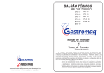
MODEL
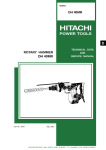
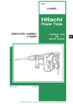
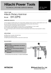
DH 50MB
POWER TOOLS
D
HAMMER DRILL
DH 50MB
LIST No. E455
TECHNICAL DATA
AND
SERVICE MANUAL
Feb. 2000
SPECIFICATIONS AND PARTS ARE SUBJECT TO CHANGE FOR IMPROVEMENT
Notice for use
Specifications and parts are subject to change for improvement.
Refer to Hitachi Power Tool Technical News for further information.
CONTENTS
[ Business Section ]
1. PRODUCT NAME
Page
• • • • • • • • • • • • • • • • • • • • • • • • • • • • • • • • • • • • • • • • • • • • • • • • • • • • • • • • • • • • • • • • • • • • • • • • • • • • • • • • • • • • • • • • • • • • • • • • • • • • • • • • • • • • • • • • • • • • • • • •
2. MARKETING OBJECTIVE
3. APPLICATIONS
• • • • • • • • • • • • • • • • • • • • • • • • • • • • • • • • • • • • • • • • • • • • • • • • • • • • • • • • • • • • • • • • • • • • • • • • • • • • • • • • • • • • • • • • • • • • • • • • • • • • • • • • • • •
1
• • • • • • • • • • • • • • • • • • • • • • • • • • • • • • • • • • • • • • • • • • • • • • • • • • • • • • • • • • • • • • • • • • • • • • • • • • • • • • • • • • • • • • • • • • • • • • • • • • • • • • • • • • • • • • • • • • • • • • • • • • •
1
4. SELLING POINTS
• • • • • • • • • • • • • • • • • • • • • • • • • • • • • • • • • • • • • • • • • • • • • • • • • • • • • • • • • • • • • • • • • • • • • • • • • • • • • • • • • • • • • • • • • • • • • • • • • • • • • • • • • • • • • • • • • • • • • • •
4-1. Selling Point Descriptions
5. SPECIFICATIONS
5-1. Specifications
3
• • • • • • • • • • • • • • • • • • • • • • • • • • • • • • • • • • • • • • • • • • • • • • • • • • • • • • • • • • • • • • • • • • • • • • • • • • • • • • • • • • • • • • • • • • • • • • • • • • • • • • • • • • • • • • • • • • • • • • •
5
• • • • • • • • • • • • • • • • • • • • • • • • • • • • • • • • • • • • • • • • • • • • • • • • • • • • • • • • • • • • • • • • • • • • • • • • • • • • • • • • • • • • • • • • • • • • • • • • • • • • • • • • • • • • • • • • • • • • • • • •
5
• • • • • • • • • • • • • • • • • • • • • • • • • • • • • • • • • • • • • • • • • • • • • • • • • • • • • • • • • • • • • • • • • • • • • • • • • • • • • • • • • • • • • • • • • • • • • • • • • • • • • • • • • • • • •
6. COMPARISONS WITH SIMILAR PRODUCTS
6-1. Specification Comparisons
6-3. Chiseling Performance
6
• • • • • • • • • • • • • • • • • • • • • • • • • • • • • • • • • • • • • • • • • • • • • • • • • • • • • • • • • • • • • • • • • • • • • • • • • • • •
10
• • • • • • • • • • • • • • • • • • • • • • • • • • • • • • • • • • • • • • • • • • • • • • • • • • • • • • • • • • • • • • • • • • • • • • • • • • • • • • • • • • • • • • • • • • • • • • • • • • • • •
10
6-2. Drilling Speed Comparisons
• • • • • • • • • • • • • • • • • • • • • • • • • • • • • • • • • • • • • • • • • • • • • • • • • • • • • • • • • • • • • • • • • • • • • • • • • • • • • • • • • • • • • • • • • • • • • • • • • • • •
••••••••••••••••••••••••••••••••••••••••••••••••••••••••••••••••••••••••••••••••••••••••••••••••••••••••••••
7. PRECAUTIONS IN SALES PROMOTION
• • • • • • • • • • • • • • • • • • • • • • • • • • • • • • • • • • • • • • • • • • • • • • • • • • • • • • • • • • • • • • • • • • • • • • • • • • • • • • • • • • • •
11
12
13
•••••••••••••••••••••••••••••••••••••••••••••••••••••••••••••••••••••••••••••••••••••••••••••••••••••••••••••••
13
••••••••••••••••••••••••••••••••••••••••••••••••••••••••••••••••••••••••••••••••••••••••••••••••••••••••••••••••••••••••••
13
7-1. Handling Instructions
7-2. Caution Plate
2
• • • • • • • • • • • • • • • • • • • • • • • • • • • • • • • • • • • • • • • • • • • • • • • • • • • • • • • • • • • • • • • • • • • • • • • • • • • • • • • • • • • • • • • • • • • • • • • • • • • • • • •
5-2. Optional Accessories
8. REFERENCES
1
• • • • • • • • • • • • • • • • • • • • • • • • • • • • • • • • • • • • • • • • • • • • • • • • • • • • • • • • • • • • • • • • • • • • • • • • • • • • • • • • • • • • • • • • • • • • • • • • • • • • • • • • • • • • • • • • • • • • • • • • • • • • •
8-1. Grease Replacement Procedures
8-2. O-Ring Replacement
14
••••••••••••••••••••••••••••••••••••••••••••••••••••••••••••••••••••••••••••••••••••••••••••
14
• • • • • • • • • • • • • • • • • • • • • • • • • • • • • • • • • • • • • • • • • • • • • • • • • • • • • • • • • • • • • • • • • • • • • • • • • • • • • • • • • • • • • • • • • • • • • • • • • • • • • • • • • • • • • •
14
8-3. Structure of the DH 50MB Hammer Drill
••••••••••••••••••••••••••••••••••••••••••••••••••••••••••••••••••••••••••••••••••
15
[ Service Section ]
9. PRECAUTIONS IN DISASSEMBLY AND REASSEMBLY
9-1. Disassembly
9-2. Reassembly
•••••••••••••••••••••••••••••••••••••••••••••••••••••••••••
23
••••••••••••••••••••••••••••••••••••••••••••••••••••••••••••••••••••••••••••••••••••••••••••••••••••••••••••••••••••••••••
23
• • • • • • • • • • • • • • • • • • • • • • • • • • • • • • • • • • • • • • • • • • • • • • • • • • • • • • • • • • • • • • • • • • • • • • • • • • • • • • • • • • • • • • • • • • • • • • • • • • • • • • • • • • • • • • • • • • • • • • • • • •
9-3. Screw Locking Agent TB1401
• • • • • • • • • • • • • • • • • • • • • • • • • • • • • • • • • • • • • • • • • • • • • • • • • • • • • • • • • • • • • • • • • • • • • • • • • • • • • • • • • • • • • • • • • • • • • • • • •
27
••••••••••••••••••••••••••••••••••••••••••••••••••••••••••••••••••••••••••••••••••••••••••••••••••••••••••••••••••
27
••••••••••••••••••••••••••••••••••••••••••••••••••••••••••••••••••••••••••••••••••••••••••••••••••••••••••••••••••••
28
9-4. Tightening Torque
9-5. Wiring Diagrams
9-6. Insulation Test
24
••••••••••••••••••••••••••••••••••••••••••••••••••••••••••••••••••••••••••••••••••••••••••••••••••••••••••••••••••••••••
9-7. No-Load Current Values
•••••••••••••••••••••••••••••••••••••••••••••••••••••••••••••••••••••••••••••••••••••••••••••••••••••••••
10. STANDARD REPAIR TIME (UNIT) SCHEDULES
28
28
• • • • • • • • • • • • • • • • • • • • • • • • • • • • • • • • • • • • • • • • • • • • • • • • • • • • • • • • • • • • • • • • • • • • • •
29
• • • • • • • • • • • • • • • • • • • • • • • • • • • • • • • • • • • • • • • • • • • • • • • • • • • • • • • • • • • • • • • • • • • • • • • • • • • • • • • • • • • • • • • • • • • • • • • • • • • •
30
[ Appendix ]
Assembly Diagram for DH 50MB
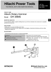
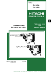
1. PRODUCT NAME
Hitachi Hammer Drill, Model DH 50MB
2. MARKETING OBJECTIVE
The market demand for 50 mm (2") class hammer drills is quickly changing from spline or hexagon bit shank
types to a SDS-MAX bit shank type, especially in the European market. The new Model DH 50MB, which
features the SDS-MAX bit shank, has been developed to meet that market demand.
The main features of the Model DH 50MB are as follows:
1) High drilling speed and impact energy
2) Shock-absorbing handle
3) 2-mode function: Hammer drilling and hammering only
4) Compact and lightweight design
5) Soft-grip handle and side handle
6) Vario Lock mechanism (12 positions)
7) Constant speed with variable speed control
8) Warning display indicating service life of carbon brushes
3. APPLICATIONS
Concrete drilling
Drilling anchor bolt holes
Crushing, chiseling, grooving, edging, cutting, stripping, compacting/tamping and roughing concrete surfaces
[Application examples]
Air conditioning
• • • • • • • • • • • • • • • •
Piping and wiring
Electric fixtures
• • • • • • • • • • • • •
••••••••••••••••
Sanitary facilities
Interior finishing
• • • • • • • • • • • • • •
• • • • • • • • • • • • • • •
Installation of air conditioners and water coolers
Electric, gas and water supply work
Installation of electric and lighting fixtures
Sanitary plumbing
Installation of seats, display counters, ducts and interior decoration
Other building, construction and repair work
--- 1 ---
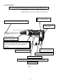
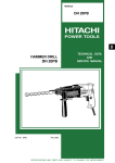
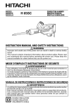
4. SELLING POINTS
Compact and lightweight: Overall length 495 mm (19-1/2"), Weight 9.8 kg (21.6 lbs.)
B
: Overall length 595 mm (23-1/2"), Weight 10.8 kg (23.8 lbs.)
C
: Overall length 610 mm (24-1/32"), Weight 10.0 kg (22.0 lbs.)
Vibration-isolating handle
reduces operator fatigue
Faster drilling speed
(About 1.8 times faster than the Model DH 40MA)
Soft-touch grip handle
and side handle
Vario lock mechanism
Tool angle can be adjusted
easily by using the grip
Change lever for switching between "Rotation +
Hammering" (for drilling), "Neutral" (for positioning the
tool tip) and "Hammering only" (for chiseling and
chipping).
Indication lamp for
carbon brush replacement
Double insulation construction
Variable speed with constant speed
Needle-pin type slip clutch
Sealed-grease construction requires minimal maintenance
Unique body design
Fig. 1
--- 2 ---
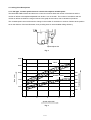
4-1. Selling Point Descriptions
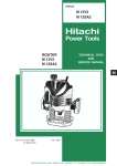
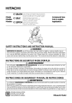
4-1-1. Dial type, constant speed electronic control with stepless variable-speed
The Model DH 50MB contains and electronic control circuit which allows the number of revolutions and the
number of strikes to be stepless adjustable from levels 1 to 5 on the dial. The number of revolutions and the
number of strikes are within the range of values in the graph shown below, due to variations of products.
The constant speed control minimizes the change in the number of revolutions or number of strikes at the position
set on the dial even if the load fluctuates, thus providing ease of use and stable drilling efficiency.
Speed-adjust dial
Fig. 2
3000
Blow
Blow (/min.)
2000
350
Rotation Speed
300
1500
250
200
1000
150
100
1
3
2
Speed-adjust dial
Fig. 3
--- 3 ---
4
5
Rotation speed (/min.)
2500
4-1-2. Faster drilling speed
The drilling speed is 1.8 times faster than that of the Model DH 40MA, as the Model DH 50MB has greater striking
energy owing to the optimized design of the rotation speed, striking frequency and the weight of striker.
4-1-3. Vibration-isolating handle offers less operator fatigue
The two vibration-isolating rubbers provided between the handle and the crank case, and also between the handle
and the housing efficiently absorb the vibration transmitted from the tool main body to minimize transmission of
vibration to the operator's arms.
Vibration-isolating rubber
Handle side
Vibration-isolating rubber
4-1-4. Indication lamp for carbon brush replacement
The indication lamp will light up (red) approximately 10 hours before the service life of the carbon brushes ends to
notify the operator that the carbon brushes should be replaced with new ones. Replacement of carbon brushes at
the proper time can prevent sudden stop of the motor and result in more efficient operation.
Indication lamp for carbon brush
replacement (red)
4-1-5. Easy-to-use tool holder
The easy-to-grip tool holder allows the tool to be attached and removed simply by sliding the grip backward.
4-1-6. Soft-touch grip handle and side handle
The double-layer molded handle and side handle consist of a plastic resin base covered with a soft plastic layer to
ensure a soft touch and easy grip of the handles.
4-1-7. Change lever for switching between "rotation + hammering", "neutral" and "hammering only"
The Model DH 50MB provides three functions, "rotation + hammering" function (for drilling), "neutral" function (for
positioning the tool tip) and "hammering only" function (for chiseling and chipping). These function modes can be
easily switched using the change lever located under the cylinder case. This permits accurate centering and
positioning because the function mode can be switched to the hammering only function mode with the drill bit (for
concrete drilling) mounted.
4-1-8. Needle-pin type slip clutch
The Model DH 50MB is equipped with a needle-pin type slip clutch to ensure a greater accuracy of slip torque and
enhanced safety.
--- 4 ---
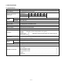
5. SPECIFICATIONS
5-1. Specifications
Capacity
Drill bit (max. diameter); 50 mm (2"), Core bit (max. diameter); 160 mm (6-1/4")
Power Source
AC single phase 50 Hz or 60 Hz
Voltage, current and
power input
Voltage (V)
110
127
220
230
240
Current (A)
13.4 12.8 11.6
6.6
6.4
6.2
115
Power input (W)
Rotation
speed
No-load
120 --- 250 /min.
Full-load
120 --- 250 /min.
1400
Full-load blow
1200 --- 2500 /min.
Type of motor
AC single-phase commutator motor
Type of switch
Trigger switch
Type of handle
D-type handle and side handle
Insulation structure
Double insulation
Material:
Housing
Glassfiber reinforced polyamide resin (green)
Handle
Glassfiber reinforced polyamide resin (black and gray)
Handle cover
Crank case cover
• • • • • • •
Enclosure
••••••••
Dimensions
495 mm x 293 mm x 120 mm (length x height x width)
(19-1/2" x 11-9/16" x 4-3/4")
Plastic case color
Off-black green
Weight
Net*
9.8 kg (21.6 lbs.)
Gross
15.2 kg (33.5 lbs.)
Packaging
Corrugated cardboard box
Standard accessories
Plastic case
Side handle
Hex. bar wrench 4 mm
Hex. bar wrench 5 mm
Hex. bar wrench 6 mm
Stopper
Grease (A)
• • • • • • • • • • • • • • • • • • • • • • • • • • • • • • • • • • • • • • • • • • • • • • • • • • • • • • • • • • • • • • • • • • • • • • • • • • • • • • • • • • • • • • • • • • • • • • • • •
•••••• • • • • • • • • • • • • • • • • • • • • • • • • • • • • • • • • • • • • • • • • • • • • • • • • • • • • • • • • • • • • • • • • • • • • • • • • • • • • • • • • • • • • • • • • • • •
• • • • • • • • • • • • • • • • • • • • • • • • • • • • • • • • • • • • • • • • • • • • • • • • • • • • • • • • • • • • • • • • • • • • • • • • • • • • • • • • •
• • • • • • • • • • • • • • • • • • • • • • • • • • • • • • • • • • • • • • • • • • • • • • • • • • • • • • • • • • • • • • • • • • • • • • • • • • • • • • • • •
• • • • • • • • • • • • • • • • • • • • • • • • • • • • • • • • • • • • • • • • • • • • • • • • • • • • • • • • • • • • • • • • • • • • • • • • • • • • • • • • •
••••••••••• • • • • • • • • • • • • • • • • • • • • • • • • • • • • • • • • • • • • • • • • • • • • • • • • • • • • • • • • • • • • • • • • • • • • • • • • • • • • • • • • • • • • • • • • • • • •
• • • • • • • • • • • • • • • • • • • • • • • • • • • • • • • • • • • • • • • • • • • • • • • • • • • • • • • • • • • • • • • • • • • • • • • • • • • • • • • • • • • • • • • • • • • • • • • • • •
*: Net weight does not include cord and side handle.
--- 5 ---
1
1
1
1
1
1
1
5-2. Optional Accessories
1. Drilling work for through-holes (rotation + hammering)
+
(1) Drill bit (SDS max shank)
Outer diameter
(mm)
Overall length
(mm)
Code No.
Outer diameter
(mm)
Overall length
(mm)
Code No.
16 (5/8")
19 (3/4")
22 (7/8")
25 (1")
28 (1-1/8")
32 (1-1/4")
38 (1-1/2")
40 (1-9/16")
340 (13-3/8")
340 (13-3/8")
320 (12-5/8")
320 (12-5/8")
370 (14-9/16")
370 (14-9/16")
370 (14-9/16")
370 (14-9/16")
313448
313449
313450
313451
313452
313453
313454
313455
16 (5/8")
19 (3/4")
22 (7/8")
25 (1")
28 (1-1/8")
32 (1-1/4")
38 (1-1/2")
40 (1-9/16")
540 (21-1/4")
540 (21-1/4")
520 (20-15/32")
520 (20-15/32")
570 (22-7/16")
570 (22-7/16")
570 (22-7/16")
570 (22-7/16")
313456
313457
313458
313459
313460
313461
313462
313463
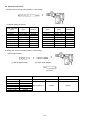
2. Driling work for anchor holes (rotation + hammering)
Drill bit (taper shank)
+
+
(1) Drill bit (taper shank)
(2) Taper shank adapter
(3) Cotter
(1) Drill bit (taper shank)
Outer diameter(mm)
11
12.3
12.7
14.3
14.5
17.5
(7/16")
(15/32")
(1/2")
(9/16")
(9/16")
(11/16")
Code No.
944460
944461
993038
944462
944500
944463
(2) Taper shank adapter
(3) Cotter
Taper dimension
Code No.
Code No.
Morse taper No. 1
313464
944477
--- 6 ---
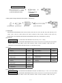
SDS-plus shank bit adapter
+
(1) Drill bit (SDS-plus shank)
+
(2) SDS-plus shank
bit adapter
Code No. 313465
3. Boring work for large-diameter holes (rotation + hammering)
(1) Guide plate
(2) Center pin
+
+
+
+
(3) Core bit
(4) Core bit shank
(1) Guide plate
Core bits with outer diameter of 32, 35, 38, 45, 50, 54, 60, 64, 70, 75, 79, 94, 100, 105, 120, 150 mm (1-1/4",
1-3/8", 1-1/2", 1-3/4", 2", 2-1/8", 2-3/8", 2-1/2", 2-3/4", 2-15/16", 3-1/8", 3-11/16", 3-15/16", 4-1/8", 4-3/4", 6")
[Guide plate is not used with core bits with outer diameter of 25 mm (1") and 29 mm (1-1/8")]
(2) Center pin
Code No. 956009 for core bits with outer diameter of 32, 35 mm (1-1/4", 1-3/8")
Code No. 955165 for core bits with outer diameter of 38, 45, 50, 54, 60, 64, 70, 75, 79, 94,100, 105, 120, 150 mm
(1-1/2", 1-3/4", 2", 2-1/8", 2-3/8", 2-1/2", 2-3/4", 2-15/16", 3-1/8", 3-11/16", 3-15/16", 4-1/8", 4-3/4", 6")
[Center pin is not used with core bits of 25 mm (1") and 29 mm (1/8")]
(3) Core bit
Outer diameter (mm)
Code No.
Outer diameter (mm)
Code No.
25 (1")
955994
75 (2-15/16")
959709
29 (1-1/8")
955995
79 (3-1/8")
955157
32 (1-1/4")
955996
94 (3-11/16")
956004
35 (1-3/8")
38 (1-1/2")
955998
959710
956000
100 (3-15/16")
105 (4-1/8")
45 (1-3/4")
955154
120 (4-3/4")
956006
50 (2")
54 (2-1/8")
959706
150 (6")
956728
60 (2-3/8")
959707
64 (2-1/2")
956002
70 (2-3/4")
959708
955159
955155
(4) Core bit shank
Code No. 313466 for core bits with outer diameter of 25, 29, 32, and 35 mm (1", 1-1/8", 1-1/4", and 1-3/8")
Code No. 313467
for core bits with outer diameter of 38, 45, 50, 54, 60, 64, 70, 75, 79, 94, 100, 105, 120, 150 mm
(1-1/2", 1-3/4", 2", 2-1/8", 2-3/8", 2-1/2", 2-3/4", 2-15/16", 3-1/8", 3-11/16", 3-15/16", 4-1/8", 4-3/4", 6")
--- 7 ---
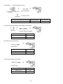
4. Hole drilling
• • • • • •
For drilling steel and wood
+
(1) 13 mm (1/2") drill chuck
(13VLA)
+
(2) Chuck adapter
(3) Chuck wrench
(1) 13 mm (1/2") drill chuck (13VLA)
(2) Chuck adapter
(3) Chuck wrench
Code No. 950272
Code No. 313468
Code No. 930515
5. Chemical anchor hole drilling work (rotation + hammering)
+
(Socket)
+
(1) Chemical anchor adapter
Socket square size
Code No.
12.7 mm (1/2")
313469
19.0 mm (3/4")
313470
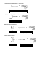
6. Demolition work (hammering)
+
(1) Bull point
Overall length
Code No.
280 mm (11")
313471
400 mm (15-3/4")
313472
7. Grooving and edging (hammering)
+
(1) Cold chisel
Overall length
Code No.
280 mm (11")
313473
400 mm (15-3/4")
313474
--- 8 ---
8. Cutting and stripping (asphalt cutting, etc.) (hammering)
+
(1) Cutter
Width
Overall length
Code No.
50 mm (2")
400 mm (15-3/4")
313475
9. Digging (substitute pick-ax) (hammering)
+
(1) Scoop
Overall length
Code No.
400 mm (15-3/4")
313476
10. Surface roughing work (hammering)
+
(1) Bushing tool
+
(2) Shank
Code No. 313477
Overall length
Code No.
220 mm (8-21/32")
313479
11. Tamping work (hammering)
+
+
(1) Rammer
(2) Shank
Code No. 313478
Overall length
Code No.
150 mm x 150 mm
220 mm (8-21/32")
313479
--- 9 ---
12. Syringe (for chip removal)
Code No. 944575
13. Impact drill grease
500 g can
70 g tube
30 g tube
Code No. 980927
Code No. 308471
Code No. 981840
Note: Code numbers listed above are subject to change without notice.
Please refer to periodic Technical News Bulletins for updates.
6. COMPARISONS WITH SIMILAR PRODUCTS
6-1. Specification Comparisons
Maker, Model
HITACHI
DH 50MB
B
D
Drill bit dia. (mm)
50 (2")
52 (2")
37 (1-7/16")
Core bit dia. (mm)
160 (6-1/4")
150 (6")
160 (6-1/4")
1400
1500
1050
No-load (/min.)
120 --- 250
120 --- 250
0 --- 255
Full-load (/min.)
120 --- 250
120 --- 250
0 --- 255
1200 --- 2500
1100 --- 2250
0 --- 2700
Catalog weight
9.8 (21.6 Ibs.)
10.8 (23.8 Ibs.)
7.9 (17.4 Ibs.)
Actual weight
10.3 (21.6 Ibs.)
10.8 (23.8 Ibs.)
N/A
Overall length (mm)
495 (19-1/2")
595 (23 -1/2")
495 (19-1/2")
Height (mm)
293 (11-9/16")
280 (11-1/32")
259 (10-7/32")
Width (mm)
120 (4-3/4")
128 (5-1/16")
115 (4-17/32")
Insulation structure
Double insulation
Double insulation
Double insulation
Full-load vibration level (dB)
120
120
119
No-load sound pressure
level (dB/A)
87
85
84
Item
Capacity
Power input (W)
Power output (W)
Rotation
speed
Full-load blow (/min.)
Dimensions
Weight
(kg)*
*Weight does not include cord and side handle.
--- 10 ---
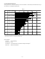
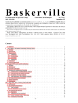
6-2. Drilling Speed Comparisons
Drilling speed varies considerably depending on the work conditions. Use the factory test results shown in Fig. 4
as a reference, for comparison purposes only.
Fig. 4
Drill bit dia.
(mm)
Maker
Model
HITACHI
B
D
DH 50MB
B
D
φ 19
HITACHI
B
D
DH 50MB
B
D
φ 22
HITACHI
B
D
DH 50MB
B
D
φ 25
HITACHI
B
D
DH 50MB
B
D
φ 28
HITACHI
B
D
DH 50MB
B
D
φ 32
HITACHI
B
D
DH 50MB
B
D
HITACHI
B
D
DH 50MB
B
D
HITACHI
B
D
DH 50MB
B
D
φ 16
φ 38
φ 40
Drilling speed (mm/min.)
0
100
200
300
400
500
480
380
340
430
320
290
370
275
250
290
225
225
240
190
190
160
130
120
110
110
75 *
90
90
60 *
*: Note that the data marked with asterisks are test results using drill bits which are beyond the tool's rated capacity. Use the
above data as a reference, for comparison purposes only.
[Test conditions]
Orientation
: Downward drilling
Pressing force : 10 kgf
Test material : Concrete panel with a compression strength of 240 kgf/cm2
Drill bit size
: SDS-max shank drill bit
--- 11 ---
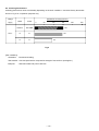
6-3. Chiseling Performance
Chiseling performance varies considerably depending on the work conditions. Use these factory test results
shown in Fig. 5 for comparison purposes only.
Demolished amount (kg/30 min.)
Voltage
Maker
supply
Model
0
HITACHI
DH 50MB
B
B
D
D
230 V
50
100
150
200
150
145
90
Fig.5
[Test conditions]
Orientation
: Downward chiseling
Test material : Concrete panel with a compression strength of 2,919 N/cm2 (240 kgf/cm2)
Bull point
: SDS-max shank bull point of 280 mm
--- 12 ---
250
7. PRECAUTIONS IN SALES PROMOTION
In the interest of promoting the safest and most efficient use of the Model DH 50MB Hammer Drill by all of our
customers, it is very important that at the time of sales the salesperson carefully ensures that the buyer seriously
recognizes the importance of the contents of the Handling Instructions, and fully understands the meaning of the
precautions listed on the Caution Plate attached to each tool.
7-1. Handling Instructions
Although every effort is made in each step of design, manufacture and inspection to provide protection against
safety hazards, the dangers inherent in the use of any electric power tool cannot be completely eliminated.
Accordingly, general precautions and suggestions for the use of electric power tools, and specific precautions and
suggestions for the use of the Hammer Drill are listed in the Handling Instructions to enhance the safe, efficient
use of the tool by the customer. Salespersons must be thoroughly familiar with the contents of the Handling
Instructions to be able to offer appropriate guidance to the customer during sales promotion.
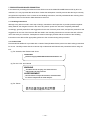
7-2. Caution Plate
Each Model DH 50MB unit is provided with a Caution Plate (illustrated below) which lists basic safety precautions
for its use. Carefully ensure that the customer fully understands and follows these precautions before using the
tool.
(1) For Australia, New Zealand and China
CAUTION
Read thoroughly HANDLING INSTRUCTIONS before use.
(2) For the U.S.A. and Canada
WARNING
To reduce the risk of injury, user must read and
understand instruction manual.
AVERTISSEMENT
Afin de reduire le risque de blessures, l'utilisateur doit
lire et bien comprendre le mode d'emploi.
(3) For Taiwan
--- 13 ---
8. REFERENCES
8-1. Grease Replacement Procedures
The electro-pneumatic hammering section and gear change section each use different kinds of grease.
It is not necessary to replenish the grease unless the tool is disassembled for repair or there is a grease leakage
due to a damaged seal.
A special grease is used for the hammering section. To change the grease in the hammering section (Cylinder
Case and Crank Case), carefully wipe the old grease off the parts, and re-lube with 30 g in the Cylinder Case and
75 g in the Crank Case (on the Connecting Rod side). Take care not to overfill with grease as an excessive
amount of grease can cause hammering failure.
The gear change section (in the Gear Cover) uses grease No. 29 for power tools. Lube with 40 g of this grease.
Do not use the special grease used for the hammering section, or it will leak to the motor parts resulting in failure
of the tool.
8-2. O-Ring Replacement
The O-ring (attached to the Striker and Piston) plays an important role to ensure air tightness. Despite its
prolonged service life due to its special rubber material, it will inevitably wear out. Early replacement, preferably
once every six months, is recommended.
--- 14 ---
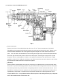
8-3. Structure of the DH 50MB Hammer Drill
Grip
Front cap
Needle
holder
Retainer
sleeve
Needle
roller
Second
hammer
Piston
Key
Striker
Air
Bevel
Cylinder
Clutch chamber gear
Connecting
rod
Crank shaft
First gear
Handle
Key slot
Needle
pin
O-ring
Second gear
Bevel pinion
Armature
Fig. 6
Torque transmission
Rotation transmission is described below with reference to Fig. 6. The gear arrangement of the Model
DH 50MB has the armature shaft positioned between the crank shaft and bevel pinion shaft. Rotation of the
armature shaft is transmitted to the second gear through the first gear of the crank shaft and the second
pinion. Then the rotation is transmitted from the second gear through the slip mechanism disposed between
the second gear and the bevel pinion shaft to turn the bevel gear. The bevel gear is keyed to the cylinder
through the clutch to rotate together. Rotation of the cylinder is transmitted to the retainer sleeve coupled
together by means of four needle pins, and then to the drill bit inserted into the retainer sleeve by way of three
key slots and two needle rollers which couple them together.
Hammering
Armature rotation is transmitted to the crank and connecting rod so that the piston moves reciprocally within
the cylinder. Air pressure developing between the piston and the striker changes with movement of the piston.
The internal pressure thus pushes the striker to repeatedly strike the end face of the second hammer. Since
the striker is moved by means of air pressure, the cushioning effect of the air absorbs the hammering shock
experienced by the operator. If air leaks from the air pressure chamber, the cushioning effect will not be
enough to absorb shock. O-rings fitted around the striker and piston for air sealing therefore play an important
role for the intended function of this hammer drill.
--- 15 ---
Switching between "Drill + Hammering", "Neutral" and "Hammering only"
Lock sleeve
Clutch
Bevel gear
The shanks of the SDS max type working tools are all
of the same shape for drill bits, bull points for chiseling
and chipping and cold chisels. When chiseling and
chipping with this hammer drill, it is necessary to stop
the drilling motion and choose the "Hammering only"
mode by means of the change lever to lock the working
tool against rotation.
The change lever mechanism is described below with
Cylinder
reference to Figs. 7, 8 and 9.
Fig. 7 is a cross-sectional view showing the "Rotation +
Change lever
Hammering" mode, in which the bevel gear dog meshes
Fig. 7
with the clutch dog to transmit rotation to the cylinder
Lock sleeve
Clutch
keyed to the clutch, so as to rotate the working tool.
Bevel gear
Fig. 8 is a sectional view showing the "Neutral" mode, in
which, with the change lever turned 90˚, the bevel gear
is brought out of engagement with the clutch to cut off
power transmission. In this position, the tool holder grip
can be manually turned to enable easier positioning of
the working tool for chiseling and chipping.
Fig. 9 is likewise a sectional view showing the
Cylinder
"Hammering only" mode. With the change lever turned
another 90˚, the clutch comes into mesh with the lock
Change lever
sleeve, and the splines on the outer circumference of
Fig. 8
the lock sleeve come into mesh with the splines on the
Lock sleeve
Clutch
Bevel gear
internal face of the cylinder case, so that the cylinder as
well as the working tool are prevented from rotating.
Since this hammer drill has three switchable modes as
mentioned above, serious accidents may result if a tool
for chipping or chiseling should be used in the
"Rotation + Hammering" mode. Ensure that your
customers are advised to always use the "Hammering"
Cylinder
mode when doing chiseling or chipping work.
Change lever
Fig. 9
--- 16 ---
Mechanism to prevent idle hammering
The arrangement against idle hammering of this hammer drill is about the same as for the DH 40MA/MB in
which, when the drill bit or bull point is no longer pressed against the concrete or similar material, the second
hammer moves to a position shown in Fig. 10 so that the striker is displaced from its hammering position. This
opens the air vent so that the piston movement causes no change in air pressure in the pressure chamber,
thus stopping the hammering action.
Second hammer
Pressure chamber
Striker
Air vent
Travel distance of the second hammer
Fig. 10
Slip mechanism
The slip mechanism is described below with reference to Fig. 11. The bevel pinion and the gear holder are
coupled together by the key and press-fitting. The springs (C) and the needle pins are housed in elongated
grooves of the gear holder. The needle pin is pressed against the inner face of the second gear by the springs
(C) to allow idle rotation of the second gear relative to the gear holder. When an excess torque is exerted on
the bevel pinion shaft, the needle pin is raised upon the projection of the second gear against the load of the
springs (C) to allow idle rotation of the second gear. With this arrangement, the clutch slips when an
excessive torque is applied to the working tool as when the drill bit contacts steel bar/wire in the concrete,
protecting the operator from unexpected motion of the side handle.
Section A-A
Key
Gear holder
Bevel pinion
Gear holder
A
Second gear
Bevel pinion
A
Elongated grooves
of the gear holder
Fig. 11
--- 17 ---
Needle pin
Spring (C)
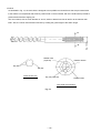
Drill bit
As illustrated in Fig. 12, the tool holder is designed to accept SDS max shank bits so that torque transmission
to the drill bit is accomplished with three key rails formed on the tool holder, with two needle rollers provided to
prevent the drill bit from slipping out.
The round shank, with an outer diameter of 18 mm, tends to attract less dust to itself or to the hammer drill
itself. Also, the runout of drill bit becomes less by making the guide length of the shank longer.
A
Needle roller
(2 pieces)
Retainer sleeve
Key slot
Key slot
Cross section A-A
Key rail (3 pieces)
Needle holder
Tool holder cross section
Fig. 12
--- 18 ---
Dia. 18 mm
A
Tool holder
The tool holder is described below with reference to Fig. 13. The drill bit inlet is covered with a front cap
(rubber) to prevent entry of cutting chips. Two needle rollers fit into the round groove of the drill bit to prevent it
from slipping out of the tool holder, while the three key rails provide positive torque transmission to the drill bit.
The drill bit can be easily removed simply be pulling back the grip. The grip is spring-loaded in the forward
direction so that pulling the grip fully backward allows the needle rollers to move away from the bit. When, on
the other hand, the drill bit is pushed fully until it stops, rotating it by hand, the latter spring back to bring the
drill bit to a locked position.
When removing the drill bit, pull the grip fully backward and pull the drill bit out.
Front cap
Needle holder
Grip
Forward
direction
Spring
Backward
direction
Needle roller (2 pieces)
Retainer sleeve
Fig. 13
--- 19 ---
Key rail (3 pieces)
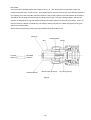
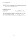
Wiring connections
The wiring connections are described below with reference to Fig. 14. The Model DH 50MB uses a plug-in
module type wiring system consisting of plug (A) ass'y and plug (B) ass'y. The internal wires (2 and 3) of the
control circuit ass'y and the internal wires from the stator, and the internal wire (5) of the control circuit ass'y
and the internal wire from the piece ass'y, are press-connected by crimp-on connectors. The rest of the
internal wires (1 and 4) of the control circuit ass'y are connected to the plug (A) ass'y, then the plug (A) ass'y is
fitted into the housing. The plug (B) ass'y is fitted into the handle section through the plug holder and is
connected with the switch terminal and cord. Wiring connection is complete when the housing section, the
handle and handle cover section are all assembled and then fastened together with screws. With such a
wiring structure, assembling and disassembling procedures associated with wiring connection have been
largely simplified over previous models.
Internal wire of stator
Connector
2
3
5
Plug (A) ass'y
Side cover
Handle
Housing
Internal wire of
piece ass'y
Switch
1
4
Control circuit ass'y
Dial
frame
Plug (B)
ass'y
Plug holder
Cord
Handle
Cord crip
Side cover
Housing
Handle cover
Plug (B) ass'y
Fig. 14
Plug (A) ass'y
--- 20 ---
Handle
cover
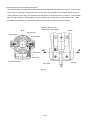
Handle and side handle
The handle section is of a two-layer structure consisting of a molded plastic base reinforced with glassfiber and
a soft plastic layer molded together on the base.
The side handle is also constructed of two layers consisting of a reinforced plastic base molded together with
steel nut and soft plastic surrounding the base.
This newly designed handle and side-handle structure ensure a lower vibration and a better, more comfortable
grip for a improved operability.
Front cap
Front cover
Grip
Cylinder case
Crank case
O-ring
O-ring
Rubber seal
Crank case cover
Tool holder
O-ring
Oil seal
O-ring
Gear cover
Oil seal
Housing
Fig. 15
Sealing and dust-proof structure
The crank case and cylinder case section are tightly sealed with four O-rings, two oil seals and rubber seals
as shown in Fig. 15. This prevents leakage of grease from the cases, while also protecting them against dust
from the outside.
The tool holder is also protected from foreign dust by means of a rubber front cap.
--- 21 ---
Indication lamp for carbon brush replacement
The indication lamp for carbon brush replacement is described below with reference to Fig. 16. As the carbon
brush wears, the guide piece mounted to the carbon brush moves toward the commutator. When the guide
piece contacts the piece ass'y, the indication lamp will light up in red as the switch is turned on. The indication
lamp will begin to light up approximately 10 hours before the service life of the carbon brushes ends. When
the indication lamp lights up, replace both carbon brushes with new ones as soon as possible.
Indication lamp (red) for
carbon brush replacement
A-A
Handle
Carbon brush
Commutator
Brush holder
A
A
Guide piece
Piece ass'y
Control circuit ass'y
Side cover
Fig. 16
--- 22 ---
Housing
9. PRECAUTIONS IN DISASSEMBLY AND REASSEMBLY
The [Bold] numbers in the descriptions below correspond to the item numbers in the Parts List and exploded
assembly diagram.
9-1. Disassembly
(1) Piston and striker
Remove the four Nylock Bolts (W/Flange) M5 x 16 [31] at the Crank Case Cover Ass'y [33] and remove the
latter. Remove the four Nylock Bolts (W/Flange) M6 x 35 [59] at the Cylinder Case [58] and pull the Cylinder
Case out of the Crank Case [35]. Pull out the Piston Pin [78] and remove the Piston [75]. Remove the
Connecting Rod Ass'y [76] from the Crank Shaft [40] by removing the Retaining Ring for D12 Shaft [39]. Pull
out the Striker [72] by hammering on the Cylinder Case with a plastic hammer. If it is difficult to pull out the
Striker, push the removed Piston together with the Connecting Rod Ass'y into the Cylinder [67] and quickly pull
them out, and the Striker will jump out together with the Piston.
(2) Removing gears from the crank case
Remove the Retaining Ring for D17 Shaft [47] and the Thrust
Bevel pinion [16]
Washer [46] from the Crank Shaft [40]. Pull out the First
Spacer [25 ]
Gear [45] with a bearing puller. Remove the Feather Key
5 x 5 x 15 [29]. Remove the Slip Clutch Ass'y [27] by
hammering the Crank Case [35] from the Gear Cover [50]
side with a plastic hammer. Remove the two Nylock Hex.
Socket Hd. Bolts M5 x 16 [38] from the Bearing Cover [43]
and pull out the Crank Shaft from the Gear Cover side.
The Slip Clutch Ass'y can be removed with the following Washer (A) [20]
procedure. First, pull out the Ball Bearing 629VV [26] with a
Sleeve
bearing puller. Support Washer (A) [20] on a sleeve as
Fig. 17
shown in Fig. 17 and release the press-fitted Bevel Pinion
[16] by pushing it from the Spacer [25] side using a hand
press. When removing the Gear Holder [21] from the
Second Gear [24], it is recommended to keep them inside a
vinyl bag during disassembly to prevent
Front Cap [1]
Springs (C) [22] and Needle Pins D6 x 6 [23] from
scattering.
(3) Disassembly of the tool holder
Slide the Grip [2] fully in direction indicated by the
arrow as shown in Fig. 18 and remove the Front
Cap [1] (since the Front Cap is made of rubber,
grasp its outer face and strongly pull it to remove).
This allows the Grip, Stopper Ring [3], Needle
Grip [2]
Fig. 18
Holder [4], Retainer Spring [5], Needle Rollers
(2 pcs.) [51] and Spring Holder [6] to be separated
from the Retainer Sleeve [52].
--- 23 ---
9-2. Reassembly
Perform reassembly in the reverse order of disassembly while observing the given precautions and taking care of
the following points.
(1) Lubrication
Apply special grease (for hammer and hammer drill) to the following portions.
Inner circumference of the Connecting Rod Ass'y [76]
Two O-Rings [73] attached to the Striker [72] and Piston [75]
Inner lip portion of the Oil Seals [10] and [92]
Fill 30 g of special grease in the Cylinder Case [58] and 75 g of special grease in the Crank Case [35] of the
connecting rod side. Apply power tool grease No. 29 to the Needle Bearing [49] and armature pinion. Fill 40 g
of power tool grease No. 29 in the gear section of the gear cover and the crank case, and 20 g between the
slip clutch (washer (A) side) and the crank case.
(2) Oil seal and others
Handle with care not to damage the Rubber Seal [34] in the Crank Case [35], two O-Rings [73] in the Piston
[75] and Striker [72], O-Ring [53] in the Second Hammer [54], O-Ring (D) [62] in the Cylinder Case [58], ORing [9] in the Front Cover [8], O-Ring [83] in the Lever Shaft [84], Oil Seal [10] in the Front Cover [8] and Oil
Seal [92] in the Gear Cover [50].
--- 24 ---
(3) Slip clutch ass'y
Press-fit the Ball Bearing 6202 [18] into the Bevel Pinion [16] and insert the Washer [19] and then Washer (A)
[20] into the Bevel Pinion. After mounting the Feather Key 3 x 3 x 8 [17] in the Bevel Pinion, press-fit the Gear
Holder [21] into the Bevel Pinion. Next, apply special grease (for hammer and hammer drill) to the inner
circumference of the Second Gear [24]. Install the Second Gear [24] on the outer circumference of the Gear
Holder and place the Needle Pins [23] without inclination as indicated in Fig. 19, then press the Springs (C)
[22]. Press in the Spacer [25] and then Ball Bearing 629 [26].
Section A-A
Gear Holder [21]
Bevel Pinion [16]
Second Gear [24]
Needle Pin [23]
Gear Holder [21]
Second Gear [24]
A
A
Spring (C) [22]
Fig. 19
(4) Inspecting the carbon brushes
The motor employs auto-stop carbon brushes. When the carbon brushes near their wear limit, the motor
stops automatically. At that time, replace both carbon brushes with new ones which have the same carbon
brush number "77" as shown in Fig. 20. In addition, always keep carbon brushes clean and ensure that they
slide freely within the brush holders.
77
Number of carbon brush
("77" denotes the last two digits of the code number.)
17 mm
Fig. 20
--- 25 ---
(Caution)
The factory-installed carbon brushes are not identical to each other as shown in Fig. 21. Pay attention to their
difference when reassembling after inspection. There is no problem when replacing them with a pair of carbon
brushes supplied as service parts (No. 77) because both parts are the same type (guide piece provided).
Handle
Housing
Carbon brush
Carbon brush
Guide piece provided
Guide piece not provided
Fig. 21
--- 26 ---
9-3. Screw Locking Agent TB1401
Apply screw locking agent ThreeBond TB1401 to all of the M5 hexagon socket head bolts (except for M8 for front
cover mounting and M6 hexagon socket head bolts for cylinder case mounting, which are special bolts to be
treated as service parts).
(Note) Be sure to apply screw locking agent ThreeBond TB1401 to the threads during reassembly, as the bolts
loosened with vibration may cause damage to the tool body.
9-4. Tightening Torque
9-4-1. Tightening torque of each screw
+ 1.96
0
+ 20
0
M5 Hex. Socket Hd. Bolt
7.84
D4 Tapping Screw
2.0
0.5 N•m (20
D5 Tapping Screw
2.9
0.49 N•m (30
Bolt for mounting the side cover (M5 x 16 Flanged Bolt)
3.92
Bolt for mounting the crank case cover (M5 x 16 Flanged Bolt)
4.9
Bolt for mounting the housing (M6 x 40 Flanged Bolt)
4.9
--- 27 ---
9.8
kgf•cm, 69.4
0.98 N•m (50
+ 1.96
0
+ 1.96
0
N•m (50
+ 20
0
+ 20
0
in-lbs.)
4.3 in-lbs.)
5 kgf•cm, 26.0
4.3 in-lbs.)
5 kgf•cm, 34.7
4.3 in-lbs.)
10 kgf•cm, 43.4
8.7 in-lbs.)
kgf•cm, 43.4
4.9 N•m (225
N•m (100
+ 17.4
0
5 kgf•cm, 17.4
0.49 N•m (40
Bolt for mounting the front cover (M8 x 25 Hex. Socket Hd. Bolt) 22.1
Bolt for mounting the cylinder case (M6 x 35 Flanged Bolt)
N•m (80
+ 17.4
0
in-lbs.)
50 kgf•cm, 195.2
kgf•cm, 86.8
+ 17.4
0
43.4 in-lbs.)
in-lbs.)
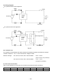
9-5. Wiring Diagrams
For products without noise suppressor
Stator
Switch
Red
Red
Control
circuit
ass'y
Armature
Plug
Connector
For products with noise suppressor
Stator
Switch
Red
Red
Noise suppressor
Control
circuit
ass'y
Armature
Plug
Pillar terminal
Fig. 22
9-6. Insulation Test
On completion of disassembly and repair, measure the insulation resistance and dielectric strength.
Insulation resistance : 7 MΩ or more with DC 500 V Megohm Tester
Dielectric strength
: AC 4,000 V/1 minute, with no abnormalities
• • • • • • •
220 V --- 240 V
(and 110 V for U.K. products)
AC 2,500 V/1 minute, with no abnormalities
• • • • • • •
110 V --- 127 V
(except U.K. products)
9-7. No-Load Current Values
After no-load operation for 30 minutes, the no-load current values should be as follows.
Voltage
110 V
115 V
127 V
220 V
230 V
240 V
Current (A) Max.
6.8 A
6.5 A
5.9 A
3.4 A
3.3 A
3.2 A
--- 28 ---
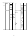
10. STANDARD REPAIR TIME (UNIT) SCHEDULES
MODEL
Variable
Fixed
10
20
30
40
50
60 min.
Work Flow
DH 50MB
Handle Cover
Switch (C)
Cord
Cord Armor
Seal Packing
Gear Cover
Needle Bearing
Tail Cover
Ball Bearing
(6201VV)
Housing Ass'y
Stator Ass'y
Armature Ass'y
Ball Bearing
(6203VV)
Dust Washer
Oil Seal
Sleeve (B)
Crank Case Cover
Rubber Seal
General Assembly
Front Cover
Front Cap
O-Ring x 2
Grip
Needle Holder Oil Seal
Retainer Spring Urethane Ring
Spring Holder Ball Bearing
(6008CM)
O-Ring
Damper
Lever Shaft
Damper Holder
Under Cover
Urethane Ring
Holder
Shaft Cover
Sleeve
Lever
Needle Roller
Spring
Retainer Sleeve
Sleeve
Second Hammer
Handle
Plug (A)
Plug (B)
Control Circuit
Side Cover Ass'y
Bevel Pinion
Key (3x3x8)
Oil Seal (A)
Ball Bearing
(6202)
Washer (A)
Gear Holder
Spring (C)
Needle Pin
Second Gear
Spacer
Ball Bearing
(629VV)
Clutch
Connecting
Rod Ass'y
Needle Bearing
Piston
Piston Pin
Striker
O-Ring
--- 29 ---
Crank Shaft
Crank Case
Feather Key
(5x5x15)
Ball Bearing
(6205)
Bearing Cover
First Gear
Second Pinion
Needle Pin
Cylinder
O-Ring (D)
Clutch Spring
Lock Sleeve
Lock Spring
Cylinder Case
Needle
Bearing x 2
Bevel Gear
Sleeve (A)
Assembly Diagram for DH 50MB
--- 30 ---
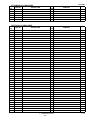
DH 50MB
PARTS
ITEM
NO.
1
CODE NO.
NO.
USED
1
DESCRIPTION
313-415
FRONT CAP
2
318-608
GRIP
1
3
318-590
STOPPER RING
1
4
313-413
NEEDLE HOLDER
1
5
313-419
RETAINER SPRING
1
6
318-589
SPRING HOLDER
1
7
880-810
NYLOCK HEX. SOCKET HD. BOLT M8X25
4
8
318-587
FRONT COVER
1
9
878-863
O-RING (S-70)
1
10
318-588
OIL SEAL (NBR710)
1
11
318-586
URETHANE RING
1
12
318-585
URETHANE RING HOLDER
1
13
318-582
RETAINING RING D40
1
14
600-8CM
BALL BEARING 6008CM
1
15
318-581
SLEEVE
1
16
318-551
BEVEL PINION
1
17
944-109
FEATHER KEY 3X3X8
1
18
620-2DD
BALL BEARING 6202DDCMPS2L
1
19
313-058
WASHER
1
20
318-552
WASHER (A)
1
21
318-554
GEAR HOLDER
1
22
318-555
SPRING (C)
8
23
313-057
NEEDLE PIN D6X6
8
24
318-553
SECOND GEAR
1
25
318-556
SPACER
1
26
629-VVM
BALL BEARING 629VVC2PS2L
1
27
318-550
SLIP CLUTCH ASS'Y
1
SDS-MAX LABEL
1
28
29
945-072
FEATHER KEY 5X5X15
2
30
944-525
BEARING WASHER (C)
1
31
313-082
NYLOCK BOLT (W/FLANGE) M5X16
6
32
991-711
DISTANCE PIECE (B)
4
33
318-584
CRANK CASE COVER ASS'Y
1
34
313-084
RUBBER SEAL
1
35
318-543
CRANK CASE
1
36
980-750
GUIDE PLATE
2
37
980-727
HANDLE RUBBER
2
38
878-181
NYLOCK HEX. SOCKET HD. BOLT M5X16
8
39
939-542
RETAINING RING FOR D12 SHAFT (10 PCS.)
1
40
318-544
CRANK SHAFT
1
41
620-5DD
BALL BEARING 6205DDCMPS2L
1
42
965-469
RETAINING RING FOR D25 SHAFT
1
43
318-548
BEARING COVER
1
44
318-545
SECOND PINION
1
45
318-546
FIRST GEAR
1
46
318-547
THRUST WASHER
1
47
967-261
RETAINING RING FOR D17 SHAFT
1
48
318-549
SEAL PACKING
1
49
939-299
NEEDLE BEARING (M661)
1
50
318-595
GEAR COVER
1
51
313-421
NEEDLE ROLLER D8X20
2
REMARKS
INCLUD.16-26
INCLUD.32
1 --- 00
--- 31 ---
DH 50MB
PARTS
ITEM
No.
52
CODE NO.
318-580
DESCRIPTION
RETAINER SLEEVE
NO.
USED
1
53
986-104
O-RING
1
54
318-564
SECOND HAMMER
1
55
318-565
DAMPER WASHER
1
56
318-566
DAMPER
1
57
318-567
DAMPER HOLDER
1
58
318-568
CYLINDER CASE
1
59
318-451
NYLOCK BOLT (W/FLANGE) M6X35
4
60
318-560
NEEDLE BEARING
1
61
981-973
CYLINDER WASHER
1
62
985-779
O-RING (D)
1
63
318-659
NEEDLE BEARING
1
64
318-559
BEVEL GEAR
1
65
313-057
NEEDLE PIN D6X6
4
66
971-750
FEATHER KEY 3X3X20
2
67
318-558
CYLINDER
1
68
318-583
SLEEVE (A)
1
69
318-563
LOCK SPRING
1
70
318-562
LOCK SLEEVE
1
71
318-631
CLUTCH SPRING
1
72
318-630
STRIKER
1
73
318-917
O-RING (FPM 710)
1
74
318-561
CLUTCH
1
75
985-772
PISTON
1
76
318-557
CONNECTING ROD ASS'Y
1
77
980-756
NEEDLE BEARING (NSK AJ50 1203)
1
78
955-593
PISTON PIN
1
79
318-574
SIDE HANDLE
1
80
318-575
HANDLE HOLDER
1
81
318-576
HANDLE BOLT
1
82
971-786
STOPPER ROD
1
83
873-095
O-RING (P-16)
1
84
318-577
LEVER SHAFT
1
85
318-578
UNDER COVER
1
86
313-411
SHAFT COVER
1
87
318-579
HEX.SOCKET HD.BOLT (W/WASHER) M4X12
2
88
313-410
LEVER
1
89
307-605
SPRING
1
90
313-424
SLEEVE
1
91
313-077
NYLOCK BOLT (W/FLANGE) M5X25
1
92
318-596
OIL SEAL (FPM 707)
1
93
620-3VV
BALL BEARING 6203VVCMPS2L
1
94
318-597
SLEEVE (B)
1
95
318-594
DUST WASHER
1
REMARKS
INCLUD.77
96
318-918
FAN
1
*
97
360-520U
ARMATURE ASS'Y 110V-115V
1
INCLUD.93-96,117,118
*
97
360-520D
ARMATURE ASS'Y 120V-127V
1
INCLUD.96
*
97
360-520E
ARMATURE ASS'Y 220V-230V
1
INCLUD.96
INCLUD.96
*
97
360-520F
ARMATURE ASS'Y 240V
1
98
318-633
FAN GUIDE
1
99
953-121
HEX. HD. TAPPING SCREW D5X50
2
1 --- 00
PARTS
* : ALTERNATIVE
--- 32 ---
DH 50MB
PARTS
ITEM
No.
* 100
CODE NO.
DESCRIPTION
340-463C
STATOR ASS'Y 110V-115V
NO.
USED
1
INCLUD.101
REMARKS
*
100
340-463D
STATOR ASS'Y 120V-127V
1
INCLUD.101
*
100
340-463E
STATOR ASS'Y 220V-230V
1
INCLUD.101
*
100
340-463F
STATOR ASS'Y 240V
1
INCLUD.101
INCLID.101 FOR USA,CAN
*
100
340-463G
STATOR ASS'Y 115V
1
101
958-032
BRUSH TERMINAL
2
102
318-607
HOUSING ASS'Y
1
HITACHI LABEL
1
103
104
318-570
NYLOCK BOLT (W/FLANGE) M6X40
6
105
307-811
TAPPING SCREW (W/FLANGE) D4X16 (BLACK)
2
106
318-599
BRUSH CAP COVER
2
107
940-540
BRUSH CAP
2
108
999-077
CARBON BRUSH (AUTO STOP TYPE) (1 PAIR)
2
109
980-487
BRUSH HOLDER
1
110
938-477
HEX. SOCKET SET SCREW M5X8
2
111
959-141
CONNECTOR 50092 (10 PCS.)
3
112
313-948
DIAL FRAME
1
NAME PLATE
1
114
318-632
PRISM
1
115
318-593
BRUSH HOLDER
1
PIECE
1
113
116
117
944-954
BEARING WASHER
1
118
620-1VV
BALL BEARING 6201VVCMPS2L
1
119
318-598
TAIL COVER
1
120
303-273
TAPPING SCREW (W/FLANGE) D5X16
3
121
305-558
TAPPING SCREW (W/FLANGE) D5X25 (BLACK)
4
122
318-571
SIDE COVER ASS'Y
1
123
318-572
HANDLE PACKING (A)
1
124
991-711
DISTANCE PIECE (B)
4
125
318-601
HANDLE
1
126
313-093
SWITCH (C) (2P SCREW TYPE W/O LOCK)
1
127
318-602
HANDLE COVER
1
128
301-653
TAPPING SCREW (W/FLANGE) D4X20 (BLACK)
2
INCLUD.109,110,115,116
INCLUD.114.123.129
129
318-573
HANDLE PACKING (B)
1
*
130
940-778
CORD ARMOR D10.7
1
*
130
958-049
CORD ARMOR D8.2
1
*
131
992-810
TERMINAL
1
*
131
980-063
TERMINAL
1
FOR SAF,AUS
*
131
930-804
TERMINAL M4.0 (10 PCS.)
1
FOR USA,CAN
*
132
960-266
CORD CLIP
1
*
132
981-987Z
CORD CLIP
1
FOR SUI
133
984-750
TAPPING SCREW (W/FLANGE) D4X16
2
*
134
500-390Z
CORD
1
(CORD ARMOR D10.7)
*
134
500-446Z
CORD
1
(CORD ARMOR D10.7) FOR GBR(230V)
*
134
500-434Z
CORD
1
(CORD ARMOR D10.7) FOR USA,CAN
*
134
500-408Z
CORD
1
(CORD ARMOR D8.2) FOR AUS
*
134
500-391Z
CORD
1
(CORD ARMOR D10.7) FOR SUI
*
134
500-460Z
CORD
1
(CORD ARMOR D10.7) FOR GBR(110V)
*
135
318-605
CONTROLLER CIRCUIT
1
*
135
318-591
CONTROLLER CIRCUIT
1
FOR GBR(110V)
*
135
318-606
CONTROLLER CIRCUIT
1
FOR USA,CAN
PARTS
* : ALTERNATIVE
--- 33 ---
1 --- 00
DH 50MB
PARTS
*
ITEM
No.
136
*
*
*
CODE NO.
DESCRIPTION
NO.
REMARKS
USED
1
FOR USA,CAN
313-092
PLUG (A)
136
313-142
PLUG (A)
1
137
959-141
CONNECTOR 50092 (10 PCS.)
1
138
318-648
PLUG (B)
1
FOR AUS
*
138
318-600
PLUG (B)
1
FOR AUS
*
138
318-649
PLUG (B)
1
FOR USA,CAN
139
938-307
PILLAR TERMINAL
1
EXCEPT AUS
140
318-603
PLUG HOLDER
1
*
1 --- 00
PARTS
* : ALTERNATIVE
--- 34 ---
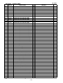
DH 50MB
STANDARD ACCESSORIES
ITEM
No.
501
CODE NO.
318-646
DESCRIPTION
CASE (PLASTIC)
NO.
USED
1
502
981-840
GREASE (A) FOR HAMMER.HAMMER DRILL (30G)
1
503
944-458
HEX. BAR WRENCH 4MM
1
504
944-459
HEX. BAR WRENCH 5MM
1
505
872-422
HEX. BAR WRENCH 6MM
1
REMARKS
OPTIONAL ACCESSORIES
ITEM
No.
CODE NO.
601
317-483
DRILL BIT (SDS MAX) D10.5X305
1
602
317-484
DRILL BIT (SDS MAX) D12.5X305
1
603
317-485
DRILL BIT (SDS MAX) D12.7X305
1
604
317-486
DRILL BIT (SDS MAX) D14.3X305
1
605
317-487
DRILL BIT (SDS MAX) D14.5X305
1
606
313-448
DRILL BIT (SDS MAX) D16X340
1
607
313-449
DRILL BIT (SDS MAX) D19X340
1
608
313-450
DRILL BIT (SDS MAX) D22X320
1
609
313-451
DRILL BIT (SDS MAX) D25X320
1
610
313-452
DRILL BIT (SDS MAX) D28X370
1
611
313-453
DRILL BIT (SDS MAX) D32X370
1
612
313-454
DRILL BIT (SDS MAX) D38X370
1
613
313-455
DRILL BIT (SDS MAX) D40X370
1
614
313-456
DRILL BIT (SDS MAX) D16X540
1
615
313-457
DRILL BIT (SDS MAX) D19X540
1
616
313-458
DRILL BIT (SDS MAX) D22X520
1
617
313-459
DRILL BIT (SDS MAX) D25X520
1
618
313-460
DRILL BIT (SDS MAX) D28X570
1
619
313-461
DRILL BIT (SDS MAX) D32X570
1
620
313-462
DRILL BIT (SDS MAX) D38X570
1
621
313-463
DRILL BIT (SDS MAX) D40X570
1
622
944-460
TAPER SHANK DRILL BIT D11X100
1
623
944-461
TAPER SHANK DRILL BIT D12.3X110
1
624
993-038
TAPER SHANK DRILL BIT D12.7X110
1
625
944-462
TAPER SHANK DRILL BIT D14.3X110
1
626
944-500
TAPER SHANK DRILL BIT D14.5X110
1
627
944-463
TAPER SHANK DRILL BIT D17.5X120
1
628
313-464
TAPER SHANK ADAPTER ASS'Y (SDS MAX) NO.1
1
629
944-477
COTTER
1
630
313-465
ADAPTER (SDS MAX) FOR SDS PLUS SHANK BIT
1
631
955-994
CORE BIT 25MM
1
632
955-995
CORE BIT 29MM
1
633
955-996
CORE BIT 32MM
1
INCLUD.651
634
955-998
CORE BIT 35MM
1
INCLUD.652
635
956-000
CORE BIT 38MM
1
INCLUD.653
636
955-154
CORE BIT 45MM
1
INCLUD.654
637
959-706
CORE BIT 50MM
1
INCLUD.655
638
955-155
CORE BIT 54MM
1
INCLUD.656
639
959-707
CORE BIT 60MM
1
INCLUD.657
640
956-002
CORE BIT 64MM
1
INCLUD.658
641
959-708
CORE BIT 70MM
1
INCLUD.659
DESCRIPTION
NO.
USED
PARTS
* : ALTERNATIVE
--- 35 ---
REMARKS
INCLUD.629
1 --- 00
DH 50MB
OPTIONAL ACCESSORIES
ITEM
No.
642
CODE NO.
NO.
USED
1
INCLUD.660
DESCRIPTION
959-709
CORE BIT 75MM
643
955-157
CORE BIT 79MM
1
INCLUD.661
644
956-004
CORE BIT 94MM
1
INCLUD.662
645
959-710
CORE BIT 100MM
1
INCLUD.663
646
955-159
CORE BIT 105MM
1
INCLUD.664
647
956-006
CORE BIT 120MM
1
INCLUD.665
648
956-728
CORE BIT 150MM
1
INCLUD.666
649
318-531
GUIDE PLATE (FOR CORE BIT 25MM)
1
650
318-532
GUIDE PLATE (FOR CORE BIT 29MM)
1
651
955-997
GUIDE PLATE (FOR CORE BIT 32MM)
1
652
955-999
GUIDE PLATE (FOR CORE BIT 35MM)
1
653
956-001
GUIDE PLATE (FOR CORE BIT 38MM)
1
654
955-166
GUIDE PLATE (FOR CORE BIT 45MM)
1
655
950-475
GUIDE PLATE (FOR CORE BIT 50MM)
1
656
955-167
GUIDE PLATE (FOR CORE BIT 54MM)
1
657
950-476
GUIDE PLATE (FOR CORE BIT 60MM)
1
658
956-003
GUIDE PLATE (FOR CORE BIT 64MM)
1
659
950-477
GUIDE PLATE (FOR CORE BIT 70MM)
1
660
950-478
GUIDE PLATE (FOR CORE BIT 75MM)
1
661
955-168
GUIDE PLATE (FOR CORE BIT 79MM)
1
662
956-005
GUIDE PLATE (FOR CORE BIT 94MM)
1
663
950-479
GUIDE PLATE (FOR CORE BIT 100MM)
1
664
955-169
GUIDE PLATE (FOR CORE BIT 105MM)
1
665
956-007
GUIDE PLATE (FOR CORE BIT 120MM)
1
666
956-743
GUIDE PLATE (FOR CORE BIT 150MM)
1
667
318-530
CENTER PIN FOR CORE BIT D25-29
1
668
956-009
CENTER PIN (B) 147L FOR CORE BIT D32-35
1
669
955-165
CENTER PIN (A) 133L FOR CORE BIT D38-150
1
670
313-466
CORE BIT SHANK (B) SDS MAX D25-35
1
671
313-467
CORE BIT SHANK (A) SDS MAX D38-150
1
672
950-272
DRILL CHUCK 13VLA
1
673
930-515
CHUCK WRENCH 10G
1
674
313-468
CHUCK ADAPTER (SDS MAX)
1
675
313-469
CHEMICAL ANCHOR ADAPTER (SDS MAX) 12.7MM
1
676
313-470
CHEMICAL ANCHOR ADAPTER (SDS MAX)19MM
1
677
313-471
BULL POINT (SDS MAX) 280L
1
678
313-472
BULL POINT (SDS MAX) 400L
1
679
313-473
COLD CHISEL (SDS MAX) 280MM
1
680
313-474
COLD CHISEL (SDS MAX) 400MM
1
681
313-475
CUTTER (SDS MAX) W50X400L
1
682
313-476
SCOOP (SDS MAX) 400L
1
683
313-477
BUSHING TOOL (SDS MAX)
1
684
313-478
RAMMER (SDS MAX) 150MM X 150MM
1
685
313-479
SHANK (SDS MAX)FOR RAMMER,BUSHING TOOL
1
686
944-575
SYRINGE
1
687
318-085
SYRINGE (BELLOWS TYPE)
1
688
308-471
GREASE FOR HAMMER.HAMMER DRILL (70G)
1
689
980-927
GREASE FOR HAMMER.HAMMER DRILL (500G)
1
1 --- 00
* : ALTERNATIVE PARTS
--- 36 ---
INCLUD.673
REMARKS