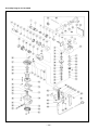
1
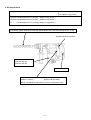
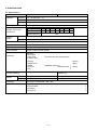
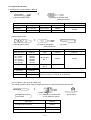
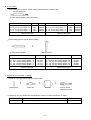
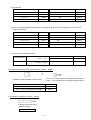
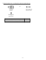
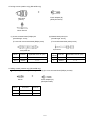
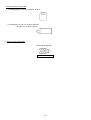
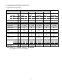
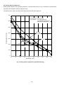
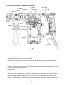
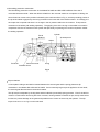
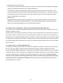
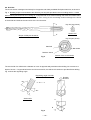
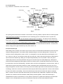
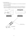
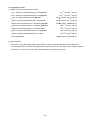
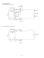
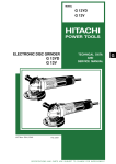
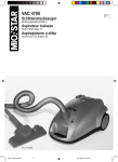
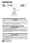
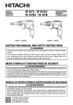
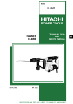
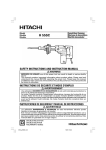
MODELS
DH 25PA
DH 25PB
POWER TOOLS
D
HAMMER DRILL
DH 25PA, DH 25PB
LIST Nos. DH 25PA: E453
DH 25PB: E454
TECHNICAL DATA
AND
SERVICE MANUAL
Nov. 1999
SPECIFICATIONS AND PARTS ARE SUBJECT TO CHANGE FOR IMPROVEMENT
REMARK:
Throughout this TECHNICAL DATA AND SERVICE MANUAL, a symbol(s)
is(are) used in the place of company name(s) and model name(s) of our
competitor(s). The symbol(s) utilized here is(are) as follows:
Competitors
Symbols Utilized
C
Company Name
Model Name
MAKITA
HR2010
Notice for use
Specifications and parts are subject to change for improvement.
Refer to Hitachi Power Tool Technical News for further information.
CONTENTS
[ Business Section ]
1. PRODUCT NAME
Page
• • • • • • • • • • • • • • • • • • • • • • • • • • • • • • • • • • • • • • • • • • • • • • • • • • • • • • • • • • • • • • • • • • • • • • • • • • • • • • • • • • • • • • • • • • • • • • • • • • • • • • • • • • • • • • • • • • • • • • • •
2. MARKETING OBJECTIVE
3. APPLICATIONS
1
• • • • • • • • • • • • • • • • • • • • • • • • • • • • • • • • • • • • • • • • • • • • • • • • • • • • • • • • • • • • • • • • • • • • • • • • • • • • • • • • • • • • • • • • • • • • • • • • • • • • • • • • • • •
1
• • • • • • • • • • • • • • • • • • • • • • • • • • • • • • • • • • • • • • • • • • • • • • • • • • • • • • • • • • • • • • • • • • • • • • • • • • • • • • • • • • • • • • • • • • • • • • • • • • • • • • • • • • • • • • • • • • • • • • • • • • •
1
4. SELLING POINTS
4-1. Selling Point Descriptions
• • • • • • • • • • • • • • • • • • • • • • • • • • • • • • • • • • • • • • • • • • • • • • • • • • • • • • • • • • • • • • • • • • • • • • • • • • • • • • • • • • • • • • • • • • • • • • • • • • • • • • • • • • • • • • • • • • • • • • •
5. SPECIFICATIONS
5-1. Specifications
5-2. Optional Accessories
• • • • • • • • • • • • • • • • • • • • • • • • • • • • • • • • • • • • • • • • • • • • • • • • • • • • • • • • • • • • • • • • • • • • • • • • • • • • • • • • • • • • • • • • • • • • • • • • • • • • • • •
• • • • • • • • • • • • • • • • • • • • • • • • • • • • • • • • • • • • • • • • • • • • • • • • • • • • • • • • • • • • • • • • • • • • • • • • • • • • • • • • • • • • • • • • • • • • • • • • • • • • • • • • • • • • • • • • • • • • • • •
• • • • • • • • • • • • • • • • • • • • • • • • • • • • • • • • • • • • • • • • • • • • • • • • • • • • • • • • • • • • • • • • • • • • • • • • • • • • • • • • • • • • • • • • • • • • • • • • • • • • • • • • • • • • • • • • • • • • • • • •
• • • • • • • • • • • • • • • • • • • • • • • • • • • • • • • • • • • • • • • • • • • • • • • • • • • • • • • • • • • • • • • • • • • • • • • • • • • • • • • • • • • • • • • • • • • • • • • • • • • • • • • • • • • • •
6. COMPARISONS WITH SIMILAR PRODUCTS
6-1. Specification Comparisons
6-2. Drilling Speed Comparisons
• • • • • • • • • • • • • • • • • • • • • • • • • • • • • • • • • • • • • • • • • • • • • • • • • • • • • • • • • • • • • • • • • • • • • • • • • • • •
• • • • • • • • • • • • • • • • • • • • • • • • • • • • • • • • • • • • • • • • • • • • • • • • • • • • • • • • • • • • • • • • • • • • • • • • • • • • • • • • • • • • • • • • • • • • • • • • • • • • •
• • • • • • • • • • • • • • • • • • • • • • • • • • • • • • • • • • • • • • • • • • • • • • • • • • • • • • • • • • • • • • • • • • • • • • • • • • • • • • • • • • • • • • • • • • • • • • • • • • • •
7. PRECAUTIONS IN SALES PROMOTION
7-1. Handling Instructions
7-2. Caution Plate
• • • • • • • • • • • • • • • • • • • • • • • • • • • • • • • • • • • • • • • • • • • • • • • • • • • • • • • • • • • • • • • • • • • • • • • • • • • • • • • • • • • •
• • • • • • • • • • • • • • • • • • • • • • • • • • • • • • • • • • • • • • • • • • • • • • • • • • • • • • • • • • • • • • • • • • • • • • • • • • • • • • • • • • • • • • • • • • • • • • • • • • • • • • • • • • • • •
• • • • • • • • • • • • • • • • • • • • • • • • • • • • • • • • • • • • • • • • • • • • • • • • • • • • • • • • • • • • • • • • • • • • • • • • • • • • • • • • • • • • • • • • • • • • • • • • • • • • • • • • • • • • • • • • • • • • • • • • •
8. REFERENCES
8-1. Grease Replacement Procedures
8-2. O-Ring Replacement
8-3. Structure of the DH 25PA and DH 25PB Hammer Drills
8-4. "Rotation Only" and "Rotation + Striking" Changeover Mechanism (DH 25PB only)
8-5. "Rotation Only" (no striking) (DH 25PB only)
8-6. Drill Bits
8-7. Chuck Section
8-8. Dust Collector (B)
• • • • • • • • • • • • • • • • • • • • • • • • • • • • • • • • • • • • • • • • • • • • • • • • • • • • • • • • • • • • • • • • • • • • • • • • • • • • • • • • • • • • • • • • • • • • • • • • • • • • • • • • • • • • • • • • • • • • • • • • • • • • •
• • • • • • • • • • • • • • • • • • • • • • • • • • • • • • • • • • • • • • • • • • • • • • • • • • • • • • • • • • • • • • • • • • • • • • • • • • • • • • • • • • • • • • • • • • •
• • • • • • • • • • • • • • • • • • • • • • • • • • • • • • • • • • • • • • • • • • • • • • • • • • • • • • • • • • • • • • • • • • • • • • • • • • • • • • • • • • • • • • • • • • • • • • • • • • • • • • • • • • • • • •
••••••••••••••••••••••••••••••••••••••••••••••••••••••••••••
• • • • • • • • • • • • • • • • • • • •
• • • • • • • • • • • • • • • • • • • • • • • • • • • • • • • • • • • • • • • • • • • • • • • • • • • • • • • • • • • • • • • • • • • • • • • • • • • •
• • • • • • • • • • • • • • • • • • • • • • • • • • • • • • • • • • • • • • • • • • • • • • • • • • • • • • • • • • • • • • • • • • • • • • • • • • • • • • • • • • • • • • • • • • • • • • • • • • • • • • • • • • • • • • • • • • • • • • • • • • • • • • ••
• • • • • • • • • • • • • • • • • • • • • • • • • • • • • • • • • • • • • • • • • • • • • • • • • • • • • • • • • • • • • • • • • • • • • • • • • • • • • • • • • • • • • • • • • • • • • • • • • • • • • • • • • • • • • • • • • • • • • • •
• • • • • • • • • • • • • • • • • • • • • • • • • • • • • • • • • • • • • • • • • • • • • • • • • • • • • • • • • • • • • • • • • • • • • • • • • • • • • • • • • • • • • • • • • • • • • • • • • • • • • • • • • • • • • • • • • • •
2
3
4
4
5
11
11
12
13
13
13
14
14
14
15
17
17
18
19
19
[ Service Section ]
9. PRECAUTIONS IN DISASSEMBLY AND REASSEMBLY
9-1. Disassembly
9-2. Reassembly
9-3. Tightening Torque
9-4. Wiring Diagrams
9-5. Wiring Work
9-6. Insulation Tests
9-7. No-Load Current Value
•••••••••••••••••••••••••••••••••••••••••••••••••••••••••••
••••••••••••••••••••••••••••••••••••••••••••••••••••••••••••••••••••••••••••••••••••••••••••••••••••••••••••••••••••••••••
••••••••••••••••••••••••••••••••••••••••••••••••••••••••••••••••••••••••••••••••••••••••••••••••••••••••••••••••••••••••••
• • • • • • • • • • • • • • • • • • • • • • • • • • • • • • • • • • • • • • • • • • • • • • • • • • • • • • • • • • • • • • • • • • • • • • • • • • • • • • • • • • • • • • • • • • • • • • • • • • • • • • • • • • • • • • • • • •
••••••••••••••••••••••••••••••••••••••••••••••••••••••••••••••••••••••••••••••••••••••••••••••••••••••••••••••••••••
• • • • • • • • • • • • • • • • • • • • • • • • • • • • • • • • • • • • • • • • • • • • • • • • • • • • • • • • • • • • • • • • • • • • • • • • • • • • • • • • • • • • • • • • • • • • • • • • • • • • • • • • • • • • • • • • • • • • • • • • • • •
• • • • • • • • • • • • • • • • • • • • • • • • • • • • • • • • • • • • • • • • • • • • • • • • • • • • • • • • • • • • • • • • • • • • • • • • • • • • • • • • • • • • • • • • • • • • • • • • • • • • • • • • • • • • • • • • • • • • • •
• • • • • • • • • • • • • • • • • • • • • • • • • • • • • • • • • • • • • • • • • • • • • • • • • • • • • • • • • • • • • • • • • • • • • • • • • • • • • • • • • • • • • • • • • • • • • • • • • • • • • • • • • • •
10. STANDARD REPAIR TIME (UNIT) SCHEDULES
[ Appendix ]
Assembly Diagram for DH 25PA
Assembly Diagram for DH 25PB
• • • • • • • • • • • • • • • • • • • • • • • • • • • • • • • • • • • • • • • • • • • • • • • • • • • • • • • • • • • • • • • • • • • • • • •
• • • • • • • • • • • • • • • • • • • • • • • • • • • • • • • • • • • • • • • • • • • • • • • • • • • • • • • • • • • • • • • • • • • • • • • • • • • • • • • • • • • • • • • • • • • • • • • • • • • •
••••••••••••••••••••••••••••••••••••••••••••••••••••••••••••••••••••••••••••••••••••••••••••••••••••
21
21
24
25
26
27
28
28
29
30
36
1. PRODUCT NAME
Hitachi Hammer Drill (Rotation + Striking: single-mode), Model DH 25PA
Hitachi Hammer Drill (Rotation + Striking, Rotation only: dual-mode), Model DH 25PB
2. MARKETING OBJECTIVE
The Model DH 25PB is a major modification of the Model DH 20V. With a more powerful motor and striker, this
hammer drill provides improved concrete drilling capacity (maximum drill bit dia. 25 mm) and faster drilling speed
than the previous model.
The Model DH 25PB is compact and lightweight, and the double-layer molded handle consists of a plastic resin
base covered with a soft plastic layer to ensure a soft touch and firm, non-slip grip. This series includes the
single-mode operation hammer drill Model DH 25PA equipped with a "Rotation + Striking" function, which is based
on the Model DH 25PB.
3. APPLICATIONS
(1) Rotation and striking function
Drilling anchor holes
Drilling holes in concrete, tile, brick and similar materials
(2) Rotation only function
Drilling holes in steel and wood (with chuck adapter)
Tightening and loosening machine screws and wood screws (with chuck adapter)
[Typical applications]
Air conditioning
• • • • • • • • • • • • • • • • • • • • • • • • • • • • • • • •
Piping and plumbing
Electrical work
• • • • • • • • • • • • • • • • • • • • • • • •
• • • • • • • • • • • • • • • • • • • • • • • • • • • • • • • • •
Interior decoration
• • • • • • • • • • • • • • • • • • • • • • • • • • •
Installation of air conditioners, water coolers and heaters, and air ducts
Installation of gas, water, and sanitary facilities
Installation of light fixtures and various electric appliances
Installation of seating, display stands, and partitions
Other civil engineering, construction and repair work
--- 1 ---
4. SELLING POINTS
Compact and lightweight: Overall length 318 mm (12-17/32"), Weight
DH 25PA 3.3 kg (7.3 lbs.)
DH 25PB 3.4 kg (7.5 lbs.)
DH 25V: Overall length 352 mm (13-7/8"), Weight 4.4 kg (9.7 lbs.)
DH 20V: Overall length 352 mm (13-7/8"), Weight 3.1 kg (6.8 lbs.)
B
: Overall length 287 mm (11-5/16"), Weight 3.1 kg (6.8 lbs.)
Fast drilling speed: About 20% faster than the Model DH 20V when the pressing force is 10 kgf.
Variable speed control switch
Powerful 650 W motor
(DH 25V: 600 W)
(DH 20V: 460 W)
Soft-touch handle
Rotation + Striking, Rotation only: dual-mode (DH 25PB only)
Rotation + Striking
: single-mode (DH 25PA)
NOTE: The Model DH 25PA does not have a changeover knob.
--- 2 ---
4-1. Selling Point Descriptions
4-1-1. Fast drilling speed
The drilling speed is 20% faster than the Model DH 20V as the Models DH 25PA and DH 25PB have great striking
energy owing to the optimum design of the rotation speed, striking frequency and the weight of striker. The
Models DH 25PA and DH 25PB can drill holes in concrete with a maximum drill bit diameter of 25 mm.
4-1-2. Powerful 650 W motor
Although the motor is the same size as the Model DH 20V, power consumption was raised to 650 W by improving
the winding specifications and the motor cooling efficiency. These are powerful hammer drills that are also
compact and lightweight.
4-1-3. Variable-speed control switch
The variable-speed control switch allows the rotation speed to be changed freely throughout the drilling operation.
This permits easy centering and positioning, and ensures more effective drilling of fragile materials such as tile
and brick.
4-1-4. Soft-touch handle
The double-layer molded handle consists of a plastic resin base covered with a soft plastic layer to ensure a soft
touch and firm, non-slip grip of the handle.
--- 3 ---
5. SPECIFICATIONS
5-1. Specifications
Model
Capacity
DH 25PA
Concrete
3.4 --- 25 mm (1/8" --- 1")
Steel
13 mm (1/2")
Wood
32 mm (1-1/4")
Power source
DH 25PB
AC single phase 50 Hz or 60 Hz
Voltage, current and
power input
Voltage (V)
110
115
120
127
220
230
240
Current (A)
6.2
5.9
5.7
5.4
3.1
3.0
2.8
Power input (W)
Rotation
speed
No-load
0 --- 1100 /min
Full-load
0 --- 800 /min
650
Full-load blow rate
0 --- 4000/min
Type of motor
AC single-phase commutator motor
Type of switch
Variable switch
Type of handle
D-type handle and side handle
Enclosure
Materials:
Gear cover
Crank case
Cylinder case
••• • • • • •
Housing
Handle cover
Handle
Tail cover
Grip
(green)
(gray)
••• • • • • •
Glassfiber reinforced
polyamide resin
Rotation and striking
Rotation and striking
Rotation only
Net*
3.3 kg (7.3 lbs.)
3.4 kg (7.5 lbs.)
Gross
5.9 kg (13.0 lbs.)
6.0 kg (13.2 lbs.)
Function mode(s)
Weight
Aluminum alloy die casting (silver)
Packaging
Corrugated cardboard box with case
Standard accessories
(1) Case
(2) Side handle
(3) Stopper
(4) Dust cup
(black)
• • • • • • • • • • • • • • • • • • • • • • • • • • • • • • • • • • • • • • • • • • • • • • • • • • • • • • • • • • • • • • • • • • • • • • • • • • • • • • • • • • • • • • • • • • • • • • • • • • • • • • •
••••••• • • • • • • • • • • • • • • • • • • • • • • • • • • • • • • • • • • • • • • • • • • • • • • • • • • • • • • • • • • • • • • • • • • • • • • • • • • • • • • • • • • • • • • •
••••••••••••• • • • • • • • • • • • • • • • • • • • • • • • • • • • • • • • • • • • • • • • • • • • • • • • • • • • • • • • • • • • • • • • • • • • • • • • • • • • • • • • • • • • • • • •
••••••••••• • • • • • • • • • • • • • • • • • • • • • • • • • • • • • • • • • • • • • • • • • • • • • • • • • • • • • • • • • • • • • • • • • • • • • • • • • • • • • • • • • • • • • • •
*: Weight excludes cord and side handle.
--- 4 ---
1
1
1
1
5-2. Optional Accessories
A. Drilling anchor holes (rotation + striking)
Drill bit (slender shaft)
+
(1) Drill bit (slender shaft)
(2) Adapter for slender shaft
(SDS-plus shank)
Drill bit (slender shaft)
Outer dia. (mm)
Adapter for slender shaft
Effective length (mm)
Overall length (mm)
Code No.
3.4 (1/8")
45 (1-25/32")
90 (3-17/32")
306369
3.5 (9/64")
45 (1-25/32")
90 (3-17/32")
306368
Code No.
306370
Drill bit (taper shank)
+
(1) Drill bit (taper shank)
(2) Taper shank adapter
(SDS-plus shank)
(1) Drill bit (taper shank)
Outer dia. (mm)
11
12.3
12.7
14.3
14.5
17.5
(7/16")
(31/64")
(1/2")
(9/16")
(73/128")
(11/16")
(3) Cotter
(2) Taper shank adapter
(3) Cotter
Code No.
Type
Code No.
Code No.
944460
944461
993038
944462
944500
944463
Morse taper
No. 1
303617
944477
Morse taper
No. 2
303618
21.5 (27/32")
944464
Part name
Code No.
A-taper
303619
B-taper
303620
Taper shank adapter (A-taper or B-taper) is provided as an
optional accessory, but drill bit is not provided.
13 mm Hammer drill chuck (DH 25PB only)
For drilling operations when using a straight shank bit for impact drilling with a hammer drill
+
Rubber cap
Straight shank bit for
impact drills
13mm (1/2") Hammer drill
chuck (SDS-plus shank)
Part name
Code No.
13mm (1/2") Hammer drill chuck
(including chuck wrench)
303332
Chuck wrench
303334
Rubber cap
303335
--- 5 ---
Chuck wrench
B. Anchor setting
Anchor setting bar to permit anchor setting operation with the hammer drill
Anchor setting bar
Anchor setting adapter (SDS-plus shank)
Part name
W - 1/4
W - 5/16
W - 3/8
W - 3/8
Overall length
Code No.
260
260
160
260
302976
302975
303621
302974
Anchor setting adapter - A
Anchor setting adapter - A
Anchor setting adapter - A
Anchor setting adapter - A
Part name
W - 1/4
W - 5/16
W - 3/8
W - 3/8
Anchor setting adapter - B
Anchor setting adapter - B
Anchor setting adapter - B
Anchor setting adapter - B
Overall length
Code No.
260
260
160
260
302979
302978
303622
302977
External cone type
Internal cone type
Anchor setting bar for manual anchor setting
+
Anchor setting adapter
Manual hammer
Part name
W - 1/4
W - 5/16
W - 3/8
W - 1/2
W - 5/8
Part name
Code No.
Anchor setting adapter - A
Anchor setting adapter - A
Anchor setting adapter - A
Anchor setting adapter - A
Anchor setting adapter - A
971794
971795
971796
971797
971798
W - 1/4
W - 5/16
W - 3/8
W - 1/2
W - 5/8
Code No.
Anchor setting adapter - B
Anchor setting adapter - B
Anchor setting adapter - B
Anchor setting adapter - B
Anchor setting adapter - B
971799
971800
971801
971802
971803
External cone type
Internal cone type
C. Large hole boring (rotation + striking)
Center pin, core bit, core bit shank and guide plate
+
+
(Guide plate)
Center pin
+
Core bit
Core bit shank
(SDS-plus shank)
(1) Center pin (Do not use bit with outer diameter of 25 mm (31/32") and 29 mm (1-5/32").
Center pin (A)
Core bit (outer diameter) 32, 35, 38 mm (1-1/4", 1-3/8", 1-1/2")
Code No. 982684
Center pin (B)
Core bit (outer diameter) 45, 50, 65, 80, 90 mm (1-25/32", 2", 2-9/16", 3-5/32", 3-9/16")
Code No. 982685
--- 6 ---
(2) Guide plate
Core bit (outer diameter) (mm)
Code No.
Core bit (outer diameter)
Code No.
32 (1-1/4")
982686
50 (2")
982690
35 (1-3/8")
982687
65
982691
38 (1-1/2")
982688
80
982692
45 (1-25/32")
982689
90
982693
(3) Core bit with guide plate (the guide plate is not required for 25 mm (31/32") and 29 mm (1-5/32") outer
diameter core bits.)
Outer diameter (mm)
Code No.
Outer diameter (mm)
Code No.
25 (31/32")
982672
45 (1-25/32")
982677
29 (1-5/32")
982673
50 (2")
982678
32 (1-1/4")
982674
65
982679
35 (1-3/8")
982675
80
982680
38 (1-1/2")
982676
90
982681
(4) Core bit shank (SDS-plus shank)
Core bit shank (A)
Core bit shank (B)
Core bit (outer diameter) 25 --- 38 mm
(31/32" --- 1-1/2")
Core bit (outer diameter) 45 --- 90 mm
(1-25/32" --- 3-9/16")
Overall length 105 mm (4-1/8")
Code No. 303625
Overall length 300 mm (11-52/64") Code No. 303626
Overall length 300 mm (11-52/64") Code No. 303627
D. Bolt placing operations with chemical anchor (rotation + striking)
+
(Standard sockets available on the market)
12.7 mm (1/2") Chemical anchor adapter (SDS-plus shank)
19 mm (3/4") Chemical anchor adapter (SDS-plus shank)
Part name
Code No.
12.7 mm (1/2") Chemical anchor adapter
303044
19 mm
303045
(3/4") Chemical anchor adapter
E. Demolishing operations (rotation + striking)
Bull point (round type only)
(SDS-plus shank)
Code No. 303046
--- 7 ---
F. Drilling hole (rotation only) ... for drilling holes in steel and wood (DH 25PB only)
+
Chuck adapter (D)
(SDS-plus shank)
Drill chuck
(13VLA)
Chuck wrench
Part name
Code No.
Chuck adapter (D) (for SDS-plus shank type)
303624
13 mm (1/2") Drill chuck 13VLA (with chuck wrench)
950272
--- 8 ---
G. Driving screws (rotation only) (DH 25PB only)
+
Chuck adapter (D)
(SDS-plus shank)
Drill chuck
(13VLA)
Chuck wrench
(1) Cross-recessed head (Phillips) bit
(2) Slotted-head (minus) bit
[Overall length: 70 mm]
[Overall length: 50 mm]
(For use with cross-recessed head (Phillips) screw)
(For use with slotted-head (minus) screw)
Tip thickness
Stamped bit No.
Bit No.
Code No.
Applicable screw dia. (mm)
Bit tip
thickness
Code No.
Applicable screw dia. (mm)
No. 2
955654
3 --- 5
0.8
955658
4
No. 3
955655
6 --- 8
1
955673
5 --- 6
H. Drilling screws (rotation only) (DH 25PB only)
Plus (Phillips) driver bit [overall length: 25 mm] (for cross-recessed head (Phillips) screws)
+
Bit No.
Chuck adapter (D)
(SDS-plus shank)
Bit No.
Screw size
Code No.
No. 2
3 --- 5 mm
971511Z
No. 3
6 --- 8 mm
971512Z
--- 9 ---
I. Grease for electric impact drill
Containing 500 g (17.64 oz): Code No. 980927
Containing 30 g (1.06 oz): Code No. 981840
70 g (2.5 oz): Code No. 308471
J. Dust cup, dust collector (B)
Dust collector (B) ass'y
Code No. 306885
--- 10 ---
6. COMPARISONS WITH SIMILAR PRODUCTS
6-1. Specification Comparisons
Hitachi
Maker
DH 25PA
Model
DH 25PB
DH 20V
C
DH 25V
Capacity
Concrete
mm
25 (1")
25 (1")
20 (25/32")
25 (1")
20 (25/32")
Steel
mm
13 (1/2")
13 (1/2")
13 (1/2")
13 (1/2")
13 (1/2")
Wood
mm
32 (1-1/4")
32 (1-1/4")
15 (19/32")
------
24 (15/16")
W
650
650
460
520
600
No-load rotation speed /min.
0 --- 1,100
0 --- 1,100
0 ---
900
0 ---
800
0 ---
900
Full-load rotation speed /min.
0 ---
0 ---
0 ---
700
0 ---
650
0 ---
735
Full-load blow
/min.
0 --- 4,000
0 --- 4,000
0 --- 3,500
0 --- 3,150
0 --- 4,000
No-load sound
pressure level
dB(A)
89
89
92
85
82
1 mode
2 modes
2 modes
2 modes
1 mode
SDS-plus shank
SDS-plus shank
SDS-plus shank
Round shank
SDS-plus shank
Round shank
SDS-plus shank
Round shank
Power input
800
800
Variable speed control
(Note 1)
Change mode
Safety-release clutch
(Note 1)
Bit drive system
Dimensions
Length
mm
318 (12-1/2")
318 (12-1/2")
320 (12-19/32")
352 (13-7/8")
287 (11-9/32")
Height
mm
200 (7-7/8")
210 (8-1/4")
200 (7-7/8")
221 (8-43/64")
214 (8-15/32")
Width
mm
92 (3-5/8")
92 (3-5/8")
94 (3-43/64")
100 (4")
91 (3-19/32")
3.3 (7.3 Ibs.)
3.4 (7.5 Ibs.)
3.1 (6.8 Ibs.)
4.4 (9.7 Ibs.)
3.1 (6.8 Ibs.)
Weight (Note 2)
Note 1) Mark "
kg
"
• • •
Equipped, Mark "
"
• • •
Not equipped.
2) Weight excludes cord and side handle.
--- 11 ---
6-2. Drilling Speed Comparisons
Drilling speed depends on the operating conditions. The test results shown in Fig. 1 are based on actual tests at
the factory and should be used as a reference only.
The drill bits which used in the test are the Hitachi genuine SDS-plus shank bits.
700
Pressing force: 98 N (10 kgf)
Test material: Concrete panel with
a compression strength of
2352 N/cm2 (240 kgf/cm2)
600
Drilling speed (mm/min.)
500
DH 25PA
DH 25PB
400
300
DH 25V
C
200
DH 20V
100
0
6
8
10
12
14
16
18
20
Drill bit dia. (mm)
Fig. 1 Drilling speed comparisons (downward drilling)
--- 12 ---
22
25
7. PRECAUTIONS IN SALES PROMOTION
In the interest of promoting the safest and most efficient use of the Models DH 25PA/PB Hammer Drills by all of
our customers, it is very important that at the time of sales the salesperson carefully ensures that the buyer
seriously recognizes the importance of the contents of the Handling Instructions, and fully understands the
meaning of the precautions listed on the Caution Plate attached to each tool.
7-1. Handling Instructions
Although every effort is made in each step of design, manufacture and inspection to provide protection against
safety hazards, the dangers inherent in the use of any electric power tool cannot be completely eliminated.
Accordingly, general precautions and suggestions for the use of electric power tools, and specific precautions and
suggestions for the use of the Hammer Drill are listed in the Handling Instructions to enhance the safe, efficient
use of the tool by the customer. Salespersons must be thoroughly familiar with the contents of the Handling
Instructions to be able to offer appropriate guidance to the customer during sales promotion.
7-2. Caution Plate
The following basic safety precautions are listed on the Name Plate attached to the main body of each tool.
However, these precautions are not listed for European countries.
For Asia and Oceania
CAUTION
Read thoroughly HANDLING INSTRUCTIONS before use.
For the U.S.A and Canada
WARNING
To reduce the risk of injury, user must read and
understand instruction manual.
AVERTISSEMENT
Afin de rèduire le risque de blessures, l'utilisateur doit lire
et bien comprendre le mode d'emloi.
--- 13 ---
8. REFERENCES
8-1. Grease Replacement Procedures
The electro-pneumatic hammering section and gear change section each use a different kind of grease. It is not
necessary to replenish the grease unless the tool is disassembled for repair or there is grease leakage due to a
damaged seal.
A special grease is used for the hammering section. To change the grease in the hammering section (Cylinder
Case and Crank Case), carefully wipe the old grease off the parts, and supply 20 g in the Cylinder Case and
17.5 g in the Crank Case (on the Connecting Rod side). Take care not to overfill the grease as an excessive
amount of grease can cause hammering failure.
The gear change section (in the Gear Cover) uses Hitachi Motor Grease No. 29 for power tools. Supply with 60 g
of this grease. Do not use the special grease used for the hammering section, or it will leak into the motor parts
and result in a failure of the tool.
8-2. O-Ring Replacement
The O-ring (attached to the Striker and Piston) plays an important role to ensure air tightness. Despite its
prolonged service life due to a special rubber material, it will inevitably wear out. Early replacement, preferably
once every six months, is recommended.
--- 14 ---
8-3. Structure of the DH 25PA and DH 25PB Hammer Drills
Grip
Front cap
Steel ball
Air chamber
Needle pin
Cylinder
Second
hammer
Striker
Key rail
(2 pieces)
Retainer
sleeve
Crank shaft
Third Piston
gear
Connecting
rod
First gear
O-ring
Second gear
Third pinion
Armature
Handle
Fig. 2
Transmission of rotation
Transmission of rotation is described with reference to Fig. 2. The gear arrangement of the Models DH 25PA
and DH 25PB is the same as that of Model DH 20V.
Rotation of the armature is transmitted to the second gear to rotate the third gear via the slip mechanism
between the second gear and the third pinion shaft. Rotation of the third gear is then transmitted to the
cylinder threaded onto the third gear. Rotation of the cylinder is transmitted to the retainer sleeve coupled
together by means of three needle pins, and then to the drill bit inserted into the retainer sleeve by way of two
key rails and a steel ball which hold the bit.
Striking function
Rotation of the armature is transmitted to the crank shaft and the connecting rod, and the piston reciprocates
within the cylinder. As the piston reciprocates, the changing air pressure inside the air chamber between the
piston and the striker causes the striker to move and continuously strike against the end of the second
hammer. At the same time, the changing air pressure within the air chamber which moves the striker also
provides an "air cushion" which absorbs the impact of the striking action.
--- 15 ---
Idle striking prevention mechanism
The idle striking prevention mechanism in the Models DH 25PA and DH 25PB is different from that of
conventional hammer drills. When the drill bit is lifted from the concrete surface on completion of drilling, the
second hammer moves to the position indicated by the continuous lines in Fig. 3, and the protruding portion at
the tip of the striker is gripped by the O-ring mounted on the inner wall of the retainer sleeve. Accordingly, the
air-escape slot is opened and there is no change in the air pressure within the air chamber. That prevents
movement of the striker (idle striking operation). The gripping force of the O-ring on the striker is so small in
comparison with the conventional mouth system that practically no pressing force at all is required to restart
the striking operation.
Cylinder
Travel
distance
Air-escape slot
Striker
Tool shaft
Second hammer
O-ring
Retainer sleeve
Fig. 3
Slip mechanism
A clutch plate holding a steel ball is inserted between the second gear and the spring plate as a slip
mechanism in the Models DH 25PA and DH 25PB. If an excessively large torque is applied to the tool shaft,
the second gear idles and does not transmit rotation.
The slip torque is adjusted by the slip plate and the belleville (coned disk) spring pressure. Even if the drill bit
comes in contact with a reinforcing bar within concrete, causing sudden excessive torque, the slip mechanism
functions to prevent damage to the gears and possible loss of control of the tool by the operator. The slip
torque is set at 2.1 to 3.1 kg•m on the tool shaft.
--- 16 ---
Sealed and dust-proof construction
The cylinder case is totally enclosed by oil seals, O-rings and other devices to prevent leakage of lubricating
grease, and to keep dust and dirt out of the internal mechanisms.
The drill bit chuck portion is protected by a rubber cap (front cap) to keep out dust and chips which could
cause improper fitting of the drill bit and/or other faulty operation of the chuck portion. The switch is also fully
dust-proofed to prevent dust and chips from entering the handle section and causing possible operational
trouble or a breakdown of the insulation.
Speed control
The Models DH 25PA and DH 25PB are equipped with a variable speed control switch which permits free
Adjustment of the rotation speed and striking force. When drilling fragile materials, pull the switch trigger
gently for low rotation speed (striking force) to achieve optimum results.
8-4. "Rotation Only" and "Rotation + Striking" Changeover Mechanism (DH 25PB only)
The change lever on the Model DH 25PB permits quick and easy changeover between the "Rotation Only" and
"Rotation + Striking" functions.
Armature rotation is transmitted to the first gear, and then to the crank shaft via the two steel balls in the groove of
the first gear. When the change lever is set to the "Rotation Only" position, the eccentric pin of the change lever
pushes up the clutch shaft and the steel balls fall in the groove. Thus the first gear idles on the crank shaft. When
the change lever is returned to the "Rotation + Striking" position, the force of the spring in the crank shaft presses
the clutch shaft back and the steel balls connect the crank shaft hole and the first gear groove to transmit rotation
to the crank shaft.
8-5. "Rotation Only" (no striking) (DH 25PB only)
To use the tool for drilling holes in steel or wood, the chuck adapter and a drill chuck (optional accessories) must
be used. Turn the change lever fully clockwise to the drill mark position to obtain "Rotation Only" function.
Since the Model DH 25PB is equipped with a change lever for changeover between "Rotation Only" and "Rotation
+ Striking" functions, merely mounting the chuck adapter will not stop the striking action; it is absolutely necessary
to turn the change lever to the "Rotation Only" setting for drilling holes in steel or wood. Should the change
lever be set to the "Rotation + Striking" position when the tool is used for drilling, the striking action may
cause the drill chuck to be broken or damaged. Sales personnel should carefully ensure that the buyer is
thoroughly advised on this point.
--- 17 ---
8-6. Drill Bits
The chuck section is designed exclusively for the popular and widely available SDS-plus shank bits, as shown in
Fig. 4. Rotating torque is transmitted to the drill bit by two key rails provided in the tool holding section. A steel
ball is used to prevent the bit from coming off. Compared with a conventional design that uses two needle rollers
to both transmit rotating torque and prevent the bit from coming off, this new design reduces damage to the shank
of the drill bit and extends the service life of the chuck section.
A
Key slot (two pieces)
Section A-A'
A'
Shape of SDS-plus shank bit
Key rail (two pieces)
Steel ball
Ball holder
Retainer sleeve
Section of the chuck section
Fig. 4
The service life of a drill bit with a diameter of 8 mm is approximately 300 holes when drilling into concrete to a
depth of 30 mm. If reground before the end of its service life, the drill bit will continue to provide efficient drilling.
Fig. 5 shows the regrinding angle.
Regrinding angle of drill bit
Rotation
direction
60
a:b=1:2
a
25
b
Section A-B
A
B
Fig. 5
--- 18 ---
130
8-7. Chuck Section
Fig. 6 shows the construction of the chuck section.
Steel ball
Front cap
Washer (B)
Holder spring
Grip
Forward
Backward
Key rails
(two pieces)
Retainer sleeve
Ball holder
Fig. 6
The opening where the drill bit is inserted is covered with a front cap (rubber) to prevent dust from entering inside.
When the drill bit is inserted, the steel ball fits in to the matching groove on the drill bit to lock it in place and
prevent it from coming off. Two key rails transmit rotating torque to the drill bit. The drill bit can be released by
simply pulling the grip back. The grip is held forward by a holder spring. To mount a drill bit, pull the grip back to
compress the holder spring. The steel ball then moves outward. While turning the drill bit, push it until it makes
contact and is fully inserted. Then release the grip so that it moves forward and fixes the drill bit. To remove the
drill bit, simply pull the grip backward fully and pull the drill bit out.
8-8. Dust Collector (B)
While drilling holes overhead, dust collector (B) can be mounted on the Models DH 25PA/PB to prevent dust and
chips from falling downward. Dust collector (B) is intended solely for use when drilling holes in concrete, and
cannot be used for drilling holes in steel or wood. It is designed for use with drill bits with overall lengths of 110
mm, 160 mm or 166 mm, and cannot be used with any longer bits. When using a drill bit with an overall length of
166 mm with dust collector (B), drilling up to a depth of approximately 72 mm is possible. When using dust
collector (B), ensure it is securely fastened to the grip on the main body with socket adapter (B). Although the
socket and socket adapter (B) rotate together with the tool shank, there is a steel ball between the outer race and
the socket which serves as a ball bearing. Should the dust cover be forced against the concrete surface, it will not
rotate even though the tool shank continues to rotate. Should the tool be operated when the dust cover is not
being held against a concrete surface, inertia may cause dust collector (B) to become disconnected from the grip.
Accordingly, caution the customer to press dust collector (B) and drill bit firmly against the concrete surface before
turning on the switch to start drilling. When dust collector (B) is used, almost no dust and chips are scattered
about. However, since the chips and dust remaining in the collector may scatter after completion of the drilling
operation, the customer should be advised to always wear protective glasses. When dust collector (B) is
disassembled for repair or maintenance, be very careful to prevent oil or grease from adhering to the steel balls.
Grease or oil on the steel balls may cause concrete dust to enter the unit and cause defective rotation.
--- 19 ---
Approx. 72 mm (2-27/32")
Approx. 16 mm (5/8")
Grip
(on the main
body side)
Drill bit
length: 166 mm
Drill bit
length: 110 mm
Socket adapter (B)
Socket
Seal cover
Dust cover Retaining ring for D30 shaft
Outer race
Washer
D6.35 Steel ball
Fig. 7 Dust collector (B) structure
--- 20 ---
9. PRECAUTIONS IN DISASSEMBLY AND REASSEMBLY
The [Bold] numbers in the descriptions below correspond to the item numbers in the Parts List and exploded
assembly diagram for DH 25PA and the <Bold> numbers to those in the Parts List and exploded assembly
diagram for DH 25PB.
9-1. Disassembly
(1) Disassembly of the Striking Mechanism Section
With a drill bit or screwdriver, push in the Second Hammer [19] <19> to release the Striker [3] <3> from the ORing (FPM 810) [20] <20>. Remove the Hex. Socket Hd. Bolt (W/Flange) [32] <32> from the Cylinder Case
[31] <31> and then remove the Cylinder Case [31] <31> from the Crank Case [46] <46>. Remove the
Connecting Rod [9] <9> from the Crank Shaft [47] <47> to remove the Piston [7] <7> from the Crank Case
[46] <46>. Lightly tap the Cylinder [2] <2> with a plastic hammer to remove the Striker [3] <3>. If the Striker
[3] <3> is hard to be removed, push the Piston [7] <7> connected with the Connecting Rod [9] <9> in the
Cylinder [2] <2> and pull it out with a jerk. Then the Striker [3] <3> can be pulled out together with the Piston
[7] <7>.
(2) Disassembly of the Retainer Section
Front Cap [26] <26>
As shown in Fig. 8, slide the Grip [27] <27> in the direction
indicated by the arrow, and remove the Front Cap [26]
<26>. The Grip [27] <27>, the Ball Holder [28] <28> inside
the Grip, the Holder Spring [29] <29>, Washer (B) [30]
<30> and the Steel Ball [14] <14> can then be removed
from the Retainer Sleeve [15] <15>.
Grip [27] <27>
Fig. 8
--- 21 ---
(3) Disassembly of the Cylinder
Remove the Cylinder Case [31] <31> from the Crank Case [46] <46> and disassemble the retainer section.
Remove the Pipe [25] <25>, then the Cylinder [2] <2> from the Cylinder Case [31] <31> by pulling it straight
toward the crank case side being careful not to scratch the Oil Seal [21] <21>.
Remove the Retaining Ring for D30 Shaft [22] <22> from the Cylinder [2] <2> and remove the Ball Bearing
6906 [23] <23> press-fitted onto the Cylinder [2] <2> with a hand press. The Retainer Sleeve [15] <15> and
the Cylinder [2] <2> can then be removed together. Remove the three Needle Pins [1] <1> from the perimeter
of the Cylinder [2] <2> and push the Retainer Sleeve [15] <15> to the outside from the inside of the Cylinder
[2] <2> with a hand press to remove the Retainer Sleeve [15] <15> and the Cylinder [2] <2>.
Remove the three Needles [16] <16> from the perimeter of the Retainer Sleeve [15] <15> and extract the ORing [20] <20> from the inner part of the Retainer Sleeve [15] <15>. The Second Hammer [19] <19> can
then be removed from the Retainer Sleeve [15] <15>. For easy extraction of this O-Ring [20] <20>, fit a
Special Repair Tool J-201 Spring Hook H-75 [J-201] onto the outer circumference of the O-Ring [20] <20>,
and pull it out. As the O-Ring [20] <20> is employed to prevent idle striking, please advise customers to
replace it with new one whenever it is disassembled. Be careful not to lose the three Needle Pins [1] <1> and
the three Needles [16] <16>.
(4) Disassembly of the Gear and the Crank Shaft in the Crank Case
The slip clutch section can be removed from the Crank Case [46] <46> by tapping the end surface of the
Crank Case [46] <46> from the gear cover side with a plastic hammer.
Remove the Retaining Ring for D8 Shaft [45] <45> and the Ball Bearing [44] <44> from the slip clutch section.
Remove the Third Pinion [34] <34> press-fitted in the Bushing [43] <43> with a hand press.
Push the Clutch Shaft <54> in the Crank Shaft [47] <47> up to the end surface with a stick having a flat edge,
then pull out the First gear [53] <51>.
Be careful not to lose the Clutch Shaft, Clutch Spring <53> and two Steel Balls D4.76 <48> in the crank shaft
hole.
(5) Disassembly of the Change Lever Ass'y in the Gear Cover
Insert the blade of a flat-blade screwdriver between the Gear Cover <57> and the Stopper Spring <56> and
twist to remove the Stopper Spring <56>.
--- 22 ---
Use of Special Repair Tools
Snap ring pliers [J-200] (See Fig. 9.)
Used to remove the Retaining Ring for D30 Shaft [22] <22> which fixes the Ball Bearing 6906 [23] <23> at
the tip end of the Cylinder [2] <2>.
Spring hook [J-201] (See Fig. 10.)
Used to extract the O-Ring [20] <20> inserted at the inner part of the Retainer Sleeve [15] <15> which is
designed to catch and grip the striker to prevent idle hammering. As shown in Fig. 11, fit the Spring Hook
[J-201] onto the O-Ring [20] <20> from the outer circumference of the O-Ring [18] <18>, and pull it out.
140
All dimensions in millimeters
45
217
1.2 dia.
R2
(1) Snap ring pliers [J-200]
(2) Spring hook [J-201]
Code No. 970976
Code No. 970977
Fig. 9
Fig. 10
Spring Hook [J-201]
O-Ring [18] <18>
Retainer
Sleeve
Fig. 11
--- 23 ---
9-2. Reassembly
Perform reassembly in the reverse order of disassembly while observing the given precautions and taking care of
the following points.
(1) Lubrication
Apply special grease to the following portions.
Both holes of the Connecting Rod [9] <9>
Inside of the Cylinder [2] <2> and the Piston Pin [8] <8>
Piston [7] <7>, outer circumference of the Striker [3] <3> and the O-Rings [4] <4>, [6] <6>
Outer circumference of the Second Hammer [19] <19>
O-Rings [18] <18>, [20] <20> for Retainer Sleeve [15] <15> and the O-Ring (D) [17] <17>
Lip portion of the Oil Seal [21] <21>
Fill 20 g of special grease in the Cylinder Case [31] <31> and 17.5 g of special grease in the Crank Case [46]
<46>. Fill 60 g of power tool grease No. 29 in the Gear Cover [54] <57>.
* Apply power tool grease No. 29 to the Steel Balls [14] <14>, [39] <39>, <48> and <72>, and Needle [16]
<16> to make reassembly work easier.
(2) Mounting the First Gear (DH 25PB only)
Insert the Clutch Spring <53> and the Clutch Shaft <54> (from the constricted side) into the hole of the Crank
Shaft <47>. Apply power tool grease No. 29 to the side hole of the crank shaft and then insert the Steel Ball
D4.76 <48>. Insert a steel bar of about 10 mm diameter having flat ends into the First Gear <51>. Pressing
the Clutch Shaft <54> so that the end surface becomes level with the end surface of the Crank Shaft <47>,
push in the First Gear <51> adjusting the first gear groove to the steel ball position.
(3) Mounting of Oil Seal [21] <21>
Prior to reassembly, apply grease to the inner circumference of the Oil Seal [21] <21>.
However, do not apply grease to its outer circumference. Also, when press-fitting the Oil Seal [21] <21>,
ensure that it is straight and level.
(4) Screw Locking Agent TB1401
Apply screw locking agent TB1401 to all hexagon socket head bolts and the Seal Lock Screw (W/Washers)
M5 x 25 [77] <87> prior to reassembly.
--- 24 ---
9-3. Tightening Torque
(1) Tightening torque of each screw and bolt
Hex. Socket Hd. Bolt (W/Flange) M5 x 25 [32] <32>
Hex. Socket Hd. Bolt (W/Flange) M5 x 45 [63] <66>
4.9
+ 1.96
0
3.43
+ 1.47
0
N•m (50
+ 20
0
kgf•cm)
N•m (35
+ 15
0
kgf•cm)
Hex. Hd. Tapping Screw D5 x 45 [58] <61>
2.94
0.49 N•m (30
5 kgf•cm)
Seal Lock Screw (W/Washers) M5 x 25 [77] <87>
2.94
0.49 N•m (30
5 kgf•cm)
Tapping Screw (W/Flange) D5 x 25 (Black) [74] <84>
2.94
0.49 N•m (30
5 kgf•cm)
1.96
+ 0.49
0
N•m (20
+5
0
kgf•cm)
1.96
+ 0.49
0
N•m (20
+5
0
kgf•cm)
Seal Lock Screw (W/SP.Washer) M4 x 12 [52] <52>
1.96
+ 0.49
0
N•m (20
+5
0
kgf•cm)
Seal Lock Screw (W/SP.Washer) M4 x 8 <70>
1.96
+ 0.49
0
N•m (20
+5
0
kgf•cm)
Tapping Screw (W/Flange) D4 x 20 (Black) [83] <93>
Tapping Screw (W/Flange) D4 x 12 (Black) <81>
Oil Cap [12] <12>
2.94
0.49 N•m (30
5 kgf•cm)
(2) Special grease
Although the newly developed grease (light yellow) is used in the Models DH 25PA and DH 25PB, the
conventional grease for hammer drill (yellow) will be supplied for the time being (Code Nos. 980927, 981840
and 308471). There is no problem even if both greases are used during servicing.
--- 25 ---
9-4. Wiring Diagrams
(1) Products with noise suppressor
CR unit
Variable switch
M1
Black
Stator
Choke coil
1
C1
Noise suppressor
Black
Armature
Cord
Black
Choke coil
C2
2
M2 Black
Stator
Fig. 12
(2) Products without noise suppressor
Variable switch
M1
1
Stator
Black
C1
Armature
Cord
C2
2
M2
Black
Stator
Fig. 13
--- 26 ---
2 Kgf•cm, 5.2
1.7 in•lbs.). Insert the lead wire
Black
(black) coming from the Stator Ass'y [68] <76> into
the terminal M1 and the lead wire (black) into the
terminal M2. Insert each lead wire (black) coming
from the Noise Suppressor [79] <89> into the
terminals C1 and C2. After the insertion, pull each
lead wire slightly to check that the lead wires do not
come off. To disconnect the lead wires, insert a
Black or
Brown
the lead wires and pull out the lead wires.
White or
Blue
small flat-blade screwdriver into the windows near
(Cord) (Cord)
Fig. 14 Connection of variable switch
--- 27 ---
(Stator)
(6
0.2 N•m
Black
tighten the screw (tightening torque: 0.6
Black
of the variable switch as shown in Fig. 14 and
(Stator)
2
and terminal
Black
Insert each cord into the terminal 1
(Noise Suppressor)
Wiring of variable switch
(Noise Suppressor)
9-5. Wiring Work
9-6. Insulation Tests
On completion of reassembly after repair, measure the insulation resistance and conduct the dielectric strength
test.
Insulation resistance: 7 MΩ or more with DC 500 V Megohm Tester
Dielectric strength
: AC 4,000 V/1 minute, with no abnormalities
• • • • • • • •
220 V --- 240 V
(and 110 V for U.K. products)
AC 2,500 V/1 minute, with no abnormalities
• • • • • • • •
110 V --- 127 V
(except for U.K. products)
9-7. No-Load Current Value
After no-load operation for 30 minutes, the no-load current value should be as follows.
Voltage (V)
110
115
120
127
220
230
240
Current (A) Max.
6.2
5.9
5.7
5.4
3.1
3.0
2.8
--- 28 ---
10. STANDARD REPAIR TIME (UNIT) SCHEDULES
MODEL
Variable
Fixed
10
20
30
40
50
Work Flow
DH 25PB
Housing Ass'y
Stator Ass'y
DH 25PA
Gear Cover
Armature Ass'y
Ball Bearing
6000DDCMPS2L
Ball Bearing
626VVC2PS2L
Switch (A)
Cord
General Assembly
Handle
Crank Shaft
Crank Case
Ball Bearing
6202DD
First Gear
Clutch Spring
Only DH 25PB
Clutch Shaft
Third Pinion
Ball Bearing
6001DDCMPS2L
Second Gear
Clutch Plate
Spring Plate
Ball Bearing
608VVC2PS2L
Front Cap
Grip
Holder Spring
Cylinder Case Oil Seal
Third Gear
Retainer
Sleeve
Pipe
Second
Urethane Ring
Hammer
Ball Bearing
(6906)
Cylinder
Connecting
Rod Steel Ball
Striker
O-Ring x 2
Piston
Oil Cap
O-Ring
--- 29 ---
60 min.
Assembly Diagram for DH 25PA
--- 30 ---
DH 25PA
PARTS
ITEM
NO.
1
CODE NO.
318-200
DESCRIPTION
NEEDLE PIN
NO.
USED
3
2
318-022
CYLINDER
1
3
318-024
STRIKER
1
4
971-760
O-RING
1
5
992-933
THIRD GEAR
1
6
971-760
O-RING
1
7
992-930
PISTON
1
8
992-931
PISTON PIN
1
9
318-020
CONNECTING ROD
1
10
980-896
SEAL PACKING (B)
1
11
980-948
O-RING
1
12
980-880
OIL CAP
1
NAME PLATE
1
14
959-156
STEEL BALL D7.0 (10 PCS.)
1
15
318-023
RETAINER SLEEVE
1
16
318-026
NEEDLE
3
17
980-890
O-RING (D)
1
13
18
318-199
O-RING
1
19
318-025
SECOND HAMMER
1
20
301-680
O-RING (FPM 810)
1
21
318-027
OIL SEAL
1
22
948-310
RETAINING RING FOR D30 SHAFT
1
23
690-6BB
BALL BEARING 6906
1
24
992-906
URETHANE RING
1
25
980-891
PIPE
1
26
318-028
FRONT CAP
1
27
318-029
GRIP
1
28
318-030
BALL HOLDER
1
29
306-342
HOLDER SPRING
1
30
984-118
WASHER (B)
1
31
318-021
CYLINDER CASE
1
32
992-253
HEX. SOCKET HD. BOLT (W/FLANGE) M5X25
4
HITACHI LABEL
1
34
992-914
THIRD PINION
1
35
600-1DD
BALL BEARING 6001DDCMPS2L
1
36
992-503
WASHER
1
37
992-928
SECOND GEAR
1
38
971-087
STOPPER WASHER
1
39
959-155
STEEL BALL D3.97 (10 PCS.)
8
40
992-916
CLUTCH PLATE
1
41
992-926
SPRING PLATE
2
42
980-877
BELLEVILLE SPRING
2
43
992-504
BUSHING
1
44
608-VVM
BALL BEARING 608VVC2PS2L
1
45
940-079
RETAINING RING FOR D8 SHAFT
1
46
980-920
CRANK CASE
1
47
318-038
CRANK SHAFT
1
48
940-220
WOODRUFF KEY 2.5X8
1
33
49
620-2DD
BALL BEARING 6202DDCMPS2L
1
50
980-871
BEARING COVER
1
51
318-040
DISTANCE COLLAR
1
PARTS
* : ALTERNATIVE
--- 31 ---
REMARKS
8 --- 99
DH 25PA
PARTS
ITEM
No.
52
*
987-203
NO.
USED
SEAL LOCK SCREW (W/SP. WASHER) M4X12 2
53
318-039
FIRST GEAR
1
54
318-352
GEAR COVER
1
55
872-470
O-RING (S-26)
1
56
600-0DD
BALL BEARING 6000DDCMPS2L
1
CODE NO.
REMARKS
DESCRIPTION
57
360-505E
ARMATURE 220V-230V
1
58
992-509
HEX. HD. TAPPING SCREW D5X45
2
59
318-035
INTERNAL WIRE
1
60
930-630
BRUSH TERMINAL
2
61
946-362
BEARING LOCK
1
EXCEPT THA
62
626-VVM
BALL BEARING 626VVC2PS2L
1
63
980-951
HEX. SOCKET HD. BOLT (W/FLANGE) M5X45
4
64
990-721
BRUSH HOLDER
2
65
999-021
CARBON BRUSH (1 PAIR)
1
65
999-070
CARBON BRUSH (AUTO STOP TYPE) (1 PAIR)
1
66
937-847
BRUSH CAP
2
67
992-911
FAN GUIDE
1
*
68
340-451F
STATOR ASS’Y 220V
1
INCLUD.60 FOR THA
*
68
340-451K
STATOR ASS’Y 220V-240V
1
INCLUD.60
69
992-500
WASHER (A)
1
70
986-812
HOUSING ASS’Y
1
71
938-477
HEX. SOCKET SET SCREW M5X8
2
72
318-018
HANDLE
1
73
980-900
PLATE
1
74
305-558
TAPPING SCREW (W/FLANGE) D5X25 (BLACK)
2
INCLUD.64,71
75
981-373
TUBE (D)
2
*
76
953-327
CORD ARMOR D8.8
1
*
76
938-051
CORD ARMOR D10.1
1
77
993-880
SEAL LOCK SCREW (W/WASHERS) M5X25
2
78
318-033
SWITCH (B)
1
*
79
994-273
NOISE SUPPRESSOR
1
EXCEPT THA
*
80
317-492
SUPPORT (B)
1
FOR NOISE SUPPRESSOR
*
81
938-307
PILLAR TERMINAL
1
82
318-019
HANDLE COVER
1
83
301-653
TAPPING SCREW (W/FLANGE) D4X20 (BLACK)
2
84
937-631
CORD CLIP
1
85
984-750
TAPPING SCREW (W/FLANGE) D4X16
2
FOR CORD
*
86
500-390Z
CORD
1
(CORD ARMOR D8.8)
*
86
500-239Z
CORD
1
(CORD ARMOR D8.8) FOR THA
*
86
500-446Z
CORD
1
(CORD ARMOR D10.1) FOR GBR
*
86
500-454Z
CORD
1
(CORD ARMOR D8.8) FOR SAF
*
86
500-457Z
CORD
1
(CORD ARMOR D8.8) FOR CHN
8 --- 99
* : ALTERNATIVE PARTS
--- 32 ---
DH 25PA
STANDARD ACCESSORIES
ITEM
No.
501
CODE NO.
NO.
USED
1
DESCRIPTION
971-787
DUST CUP
502
980-906
STOPPER ROD
1
503
980-901
SIDE HANDLE
1
504
980-905
ROD HOLDER
1
505
980-902
SIDE HANDLE HOLDER
1
506
980-904
BAND
1
507
980-903
SQUARE BOLT M8
1
508
980-939
SIDE HANDLE ASS’Y
1
509
318-307
CASE
1
REMARKS
INCLUD.503-507
OPTIONAL ACCESSORIES
ITEM
No.
CODE NO.
NO.
USED
DESCRIPTION
601
303-571
DRILL BIT (SDS PLUS) D4.0X110
1
602
303-572
DRILL BIT (SDS PLUS) D4.3X110
1
603
303-573
DRILL BIT (SDS PLUS) D4.5X110
1
604
303-574
DRILL BIT (SDS PLUS) D4.8X110
1
605
303-575
DRILL BIT (SDS PLUS) D5.0X110
1
606
303-578
DRILL BIT (SDS PLUS) D5.0X160
1
607
303-576
DRILL BIT (SDS PLUS) D5.5X110
1
608
303-577
DRILL BIT (SDS PLUS) D6.0X110
1
609
303-579
DRILL BIT (SDS PLUS) D6.0X160
1
610
303-580
DRILL BIT (SDS PLUS) D6.4X160
1
611
303-581
DRILL BIT (SDS PLUS) D6.5X160
1
612
303-582
DRILL BIT (SDS PLUS) D7.0X160
1
613
303-583
DRILL BIT (SDS PLUS) D7.5X160
1
614
303-584
DRILL BIT (SDS PLUS) D8.0X160
1
615
303-585
DRILL BIT (SDS PLUS) D8.5X160
1
616
303-586
DRILL BIT (SDS PLUS) D9.0X160
1
617
303-587
DRILL BIT (SDS PLUS) D9.5X160
1
618
303-588
DRILL BIT (SDS PLUS) D10.0X160
1
619
303-604
DRILL BIT (SDS PLUS) D10.0X260
1
620
303-589
DRILL BIT (SDS PLUS) D10.5X160
1
621
303-605
DRILL BIT (SDS PLUS) D10.5X260
1
622
303-590
DRILL BIT (SDS PLUS) D11.0X160
1
623
303-591
DRILL BIT (SDS PLUS) D12.0X166
1
624
303-606
DRILL BIT (SDS PLUS) D12.0X260
1
625
303-592
DRILL BIT (SDS PLUS) D12.5X166
1
626
303-607
DRILL BIT (SDS PLUS) D12.5X260
1
627
303-593
DRILL BIT (SDS PLUS) D12.7X166
1
* : ALTERNATIVE PARTS
--- 33 ---
REMARKS
8 --- 99
DH 25PA
OPTIONAL ACCESSORIES
ITEM
NO.
628
303-608
DRILL BIT (SDS PLUS) D12.7X260
NO.
USED
1
629
303-594
DRILL BIT (SDS PLUS) D13.0X166
1
630
303-595
DRILL BIT (SDS PLUS) D14.0X166
1
631
303-596
DRILL BIT (SDS PLUS) D14.3X166
1
632
303-609
DRILL BIT (SDS PLUS) D14.3X260
1
633
303-597
DRILL BIT (SDS PLUS) D14.5X166
1
634
303-610
DRILL BIT (SDS PLUS) D14.5X260
1
635
303-598
DRILL BIT (SDS PLUS) D15.0X166
1
636
303-599
DRILL BIT (SDS PLUS) D16.0X166
1
637
303-611
DRILL BIT (SDS PLUS) D16.0X260
1
638
303-600
DRILL BIT (SDS PLUS) D16.5X166
1
639
303-601
DRILL BIT (SDS PLUS) D17.0X166
1
640
308-485
DRILL BIT (SDS PLUS) D17.0X260
1
641
303-602
DRILL BIT (SDS PLUS) D17.5X166
1
642
303-612
DRILL BIT (SDS PLUS) D17.5X260
1
643
303-603
DRILL BIT (SDS PLUS) D18.0X166
1
644
303-613
DRILL BIT (SDS PLUS) D19.0X260
1
645
303-614
DRILL BIT (SDS PLUS) D20.0X250
1
646
303-615
DRILL BIT (SDS PLUS) D22.0X250
1
647
308-486
DRILL BIT (SDS PLUS) D24.0X250
1
648
303-616
DRILL BIT (SDS PLUS) D25.0X450
1
649
944-460
TAPER SHANK DRILL BIT D11X100
1
650
944-461
TAPER SHANK DRILL BIT D12.3X110
1
651
993-038
TAPER SHANK DRILL BIT D12.7X110
1
652
944-462
TAPER SHANK DRILL BIT D14.3X110
1
653
944-500
TAPER SHANK DRILL BIT D14.5X110
1
654
944-463
TAPER SHANK DRILL BIT D17.5X120
1
655
944-464
TAPER SHANK DRILL BIT D21.5X140
1
656
303-617
TAPER SHANK ADAPTER (SDS PLUS) NO.1
1
657
303-618
TAPER SHANK ADAPTER (SDS PLUS) NO.2
1
658
944-477
COTTER
1
659
302-976
ANCHOR SETTING ADAPTER A (SDS+)W1/4X260L
1
660
302-975
ANCHOR SETTING ADAPTER A(SDS+)W5/16X260L
1
661
303-621
ANCHOR SETTING ADAPTER A (SDS+)W3/8X160L
1
662
302-974
ANCHOR SETTING ADAPTER A (SDS+)W3/8X260L
1
663
302-979
ANCHOR SETTING ADAPTER B (SDS+)W1/4X260L
1
664
302-978
ANCHOR SETTING ADAPTER B(SDS+)W5/16X260L
1
665
303-622
ANCHOR SETTING ADAPTER B (SDS+)W3/8X160L
1
666
302-977
ANCHOR SETTING ADAPTER B (SDS+)W3/8X260L
1
667
971-794
ANCHOR SETTING ADAPTER A W1/4" (MANUAL)
1
668
971-795
ANCHOR SETTING ADAPTER A W5/16"(MANUAL)
1
669
971-796
ANCHOR SETTING ADAPTER A W3/8"(MANUAL)
1
670
971-797
ANCHOR SETTING ADAPTER A W1/2" (MANUAL)
1
671
971-798
ANCHOR SETTING ADAPTER A W5/8" (MANUAL)
1
672
971-799
ANCHOR SETTING ADAPTER B W1/4" (MANUAL)
1
673
971-800
ANCHOR SETTING ADAPTER B W5/16" (MANUAL)
1
674
971-801
ANCHOR SETTING ADAPTER B W3/8" (MANUAL)
1
675
971-802
ANCHOR SETTING ADAPTER B W1/2" (MANUAL)
1
676
971-803
ANCHOR SETTING ADAPTER B W5/8" (MANUAL)
1
677
303-044
CHEMICAL ANCHOR ADAPTER (SDS+)12.7MMX90L
1
678
303-045
CHEMICAL ANCHOR ADAPTER(SDS+)19.0MMX100L
1
6 --- 98
CODE NO.
DESCRIPTION
PARTS
* : ALTERNATIVE
--- 34 ---
REMARKS
DH 25PA
OPTIONAL ACCESSORIES
ITEM
NO.
679
CODE NO.
NO.
USED
1
INCLUD.680
DESCRIPTION
950-272
DRILL CHUCK 13VLA
680
930-515
CHUCK WRENCH 10G
1
681
982-672
CORE BIT (A) 25MM
1
682
982-673
CORE BIT (A) 29MM
1
683
982-674
CORE BIT (A) 32MM
1
INCLUD.691
684
982-675
CORE BIT (A) 35MM
1
INCLUD.692
685
982-676
CORE BIT (A) 38MM
1
INCLUD.693
686
982-677
CORE BIT (B) 45MM
1
INCLUD.694
687
982-678
CORE BIT (B) 50MM
1
INCLUD.695
688
982-679
CORE BIT (B) 65MM
1
INCLUD.696
689
982-680
CORE BIT (B) 80MM
1
INCLUD.697
690
982-681
CORE BIT (B) 90MM
1
INCLUD.698
691
982-686
GUIDE PLATE (FOR CORE BIT 32MM)
1
692
982-687
GUIDE PLATE (FOR CORE BIT 35MM)
1
693
982-688
GUIDE PLATE (FOR CORE BIT 38MM)
1
694
982-689
GUIDE PLATE (FOR CORE BIT 45MM)
1
695
982-690
GUIDE PLATE (FOR CORE BIT 50MM)
1
696
982-691
GUIDE PLATE (FOR CORE BIT 65MM)
1
697
982-692
GUIDE PLATE (FOR CORE BIT 80MM)
1
698
982-693
GUIDE PLATE (FOR CORE BIT 90MM)
1
699
982-684
CENTER PIN (A) 109L FOR CORE BIT D32-38
1
700
982-685
CENTER PIN (B) 104L FOR CORE BIT D45-90
1
701
303-625
CORE BIT SHANK (SDS PLUS) 25-38MM 105L
1
702
303-626
CORE BIT SHANK (SDS PLUS) 25-38MM 300L
1
703
303-627
CORE BIT SHANK (SDS PLUS) 45-90MM 300L
1
704
303-046
BULL POINT (SDS+) 250MM(ROUND SHANK TYPE
1
705
306-885
DUST COLLECTOR (B) ASS’Y
1
706
306-910
SOCKET ADAPTER (B)
1
707
303-619
A-TAPER SHANK ADAPTER (SDS PLUS)
1
708
303-620
B-TAPER SHANK ADAPTER (SDS PLUS)
1
709
981-840
GREASE (A) FOR HAMMER.HAMMER DRILL (30G)
1
710
308-471
GREASE FOR HAMMER.HAMMER DRILL (70G)
1
711
980-927
GREASE FOR HAMMER.HAMMER DRILL (500G)
1
* : ALTERNATIVE PARTS
--- 35 ---
REMARKS
INCLUD.706
Printed in Japan
(990830 N)
8 --- 99
Assembly Diagram for DH 25PB
--- 36 ---
DH 25PB
PARTS
ITEM
NO.
1
CODE NO.
318-200
DESCRIPTION
NEEDLE PIN
NO.
USED
3
2
318-022
CYLINDER
1
3
318-024
STRIKER
1
4
971-760
O-RING
1
5
992-933
THIRD GEAR
1
6
971-760
O-RING
1
7
992-930
PISTON
1
8
992-931
PISTON PIN
1
9
318-020
CONNECTING ROD
1
10
980-896
SEAL PACKING (B)
1
11
980-948
O-RING
1
12
980-880
OIL CAP
1
NAME PLATE
1
14
959-156
STEEL BALL D7.0 (10 PCS.)
1
15
318-023
RETAINER SLEEVE
1
16
318-026
NEEDLE
3
17
980-890
O-RING (D)
1
13
18
318-199
O-RING
1
19
318-025
SECOND HAMMER
1
20
301-680
O-RING (FPM 810)
1
21
318-027
OIL SEAL
1
22
948-310
RETAINING RING FOR D30 SHAFT
1
23
690-6BB
BALL BEARING 6906
1
24
992-906
URETHANE RING
1
25
980-891
PIPE
1
26
318-028
FRONT CAP
1
27
318-029
GRIP
1
28
318-030
BALL HOLDER
1
29
306-342
HOLDER SPRING
1
30
984-118
WASHER (B)
1
31
318-021
CYLINDER CASE
1
32
992-253
HEX. SOCKET HD. BOLT (W/FLANGE) M5X25
4
HITACHI LABEL
1
34
992-914
THIRD PINION
1
35
600-1DD
BALL BEARING 6001DDCMPS2L
1
36
992-503
WASHER
1
37
992-928
SECOND GEAR
1
38
971-087
STOPPER WASHER
1
39
959-155
STEEL BALL D3.97 (10 PCS.)
8
40
992-916
CLUTCH PLATE
1
41
992-926
SPRING PLATE
2
42
980-877
BELLEVILLE SPRING
2
43
992-504
BUSHING
1
44
608-VVM
BALL BEARING 608VVC2PS2L
1
45
940-079
RETAINING RING FOR D8 SHAFT
1
46
980-920
CRANK CASE
1
47
318-034
CRANK SHAFT
1
48
959-149
STEEL BALL D4.76 (10 PCS.)
2
33
49
620-2DD
BALL BEARING 6202DDCMPS2L
1
50
980-871
BEARING COVER
1
51
992-902
FIRST GEAR
1
PARTS
* : ALTERNATIVE
--- 37 ---
REMARKS
8 --- 99
DH 25PB
PARTS
ITEM
No.
52
987-203
NO.
USED
SEAL LOCK SCREW (W/SP. WASHER) M4X12 2
53
992-937
CLUTCH SPRING
1
54
992-938
CLUTCH SHAFT
1
55
992-506
THRUST WASHER
1
56
986-276
STOPPER SPRING
1
57
992-925
GEAR COVER
1
58
872-470
O-RING (S-26)
1
59
600-0DD
BALL BEARING 6000DDCMPS2L
1
*
60
360-505C
ARMATURE 110V
1
*
60
360-505E
ARMATURE 220V-230V
1
*
*
CODE NO.
DESCRIPTION
60
360-505F
ARMATURE 240V
1
61
992-509
HEX. HD. TAPPING SCREW D5X45
2
62
318-035
INTERNAL WIRE
1
63
930-630
BRUSH TERMINAL
2
64
946-362
BEARING LOCK
1
65
626-VVM
BALL BEARING 626VVC2PS2L
1
66
980-951
HEX. SOCKET HD. BOLT (W/FLANGE) M5X45
4
67
990-721
BRUSH HOLDER
2
68
999-021
CARBON BRUSH (1 PAIR)
1
68
999-070
CARBON BRUSH (AUTO STOP TYPE) (1 PAIR)
1
69
937-847
BRUSH CAP
2
70
991-207
SEAL LOCK SCREW (W/SP. WASHER) M4X8
1
71
992-936
BALL SPRING
1
72
959-148
STEEL BALL D3.175 (10 PCS.)
1
73
992-912
O-RING (S-8)
1
74
302-140
CHANGE LEVER ASS’Y
1
REMARKS
FOR GBR(110V)
EXCEPT THA
INCLUD.73
75
992-911
FAN GUIDE
1
*
76
340-451H
STATOR ASS’Y 110V
1
INCLUD.63 FOR GBR(110V)
*
76
340-451F
STATOR ASS’Y 220V
1
INCLUD.63 FOR THA
*
76
340-451K
STATOR ASS’Y 220V-240V
1
INCLUD.63
77
992-500
WASHER (A)
1
78
986-812
HOUSING ASS’Y
1
79
938-477
HEX. SOCKET SET SCREW M5X8
2
80
318-031
TAIL COVER
1
81
309-470
TAPPING SCREW (W/FLANGE) D4X12 (BLACK)
2
82
318-018
HANDLE
1
83
980-900
PLATE
1
INCLUD.67,79
84
305-558
TAPPING SCREW (W/FLANGE) D5X25 (BLACK)
2
*
85
981-373
TUBE (D)
2
*
86
953-327
CORD ARMOR D8.8
1
*
86
938-051
CORD ARMOR D10.1
1
87
993-880
SEAL LOCK SCREW (W/WASHERS) M5X25
2
*
88
318-033
SWITCH (B)
1
*
88
318-032
SWITCH (A)
1
FOR GBR(110V)
*
89
994-273
NOISE SUPPRESSOR
1
EXCEPT THA
*
90
317-492
SUPPORT (B)
1
FOR NOISE SUPPRESSOR
*
91
938-307
PILLAR TERMINAL
1
EXCEPT THA
92
318-019
HANDLE COVER
1
93
301-653
TAPPING SCREW (W/FLANGE) D4X20 (BLACK)
2
94
937-631
CORD CLIP
1
95
984-750
TAPPING SCREW (W/FLANGE) D4X16
2
8 --- 99
PARTS
* : ALTERNATIVE
--- 38 ---
FOR CORD
DH 25PB
PARTS
*
ITEM
No.
96
500-439Z
CORD
*
96
500-391Z
CORD
1
(CORD ARMOR D10.1) FOR SUI
*
96
500-446Z
CORD
1
(CORD ARMOR D10.1) FOR GBR(230V)
*
96
500-457Z
CORD
1
(CORD ARMOR D8.8) FOR CHN
*
96
500-390Z
CORD
1
(CORD ARMOR D8.8) FOR HOL
*
96
500-454Z
CORD
1
(CORD ARMOR D8.8) FOR SAF,GBR(110V)
CODE NO.
DESCRIPTION
NO.
REMARKS
USED
1
(CORD ARMOR D8.8) FOR AUS
STANDARD ACCESSORIES
ITEM
No.
501
CODE NO.
DESCRIPTION
NO.
USED
1
971-787
DUST CUP
502
980-906
STOPPER ROD
1
503
980-901
SIDE HANDLE
1
504
980-905
ROD HOLDER
1
505
980-902
SIDE HANDLE HOLDER
1
506
980-904
BAND
1
507
980-903
SQUARE BOLT M8
1
508
980-939
SIDE HANDLE ASS’Y
1
509
318-307
CASE
1
REMARKS
INCLUD.503-507
OPTIONAL ACCESSORIES
ITEM
No.
601
303-571
DRILL BIT (SDS PLUS) D4.0X110
NO.
USED
1
602
303-572
DRILL BIT (SDS PLUS) D4.3X110
1
603
303-573
DRILL BIT (SDS PLUS) D4.5X110
1
604
303-574
DRILL BIT (SDS PLUS) D4.8X110
1
605
303-575
DRILL BIT (SDS PLUS) D5.0X110
1
606
303-578
DRILL BIT (SDS PLUS) D5.0X160
1
607
303-576
DRILL BIT (SDS PLUS) D5.5X110
1
608
303-577
DRILL BIT (SDS PLUS) D6.0X110
1
609
303-579
DRILL BIT (SDS PLUS) D6.0X160
1
610
303-580
DRILL BIT (SDS PLUS) D6.4X160
1
611
303-581
DRILL BIT (SDS PLUS) D6.5X160
1
612
303-582
DRILL BIT (SDS PLUS) D7.0X160
1
613
303-583
DRILL BIT (SDS PLUS) D7.5X160
1
614
303-584
DRILL BIT (SDS PLUS) D8.0X160
1
615
303-585
DRILL BIT (SDS PLUS) D8.5X160
1
616
303-586
DRILL BIT (SDS PLUS) D9.0X160
1
617
303-587
DRILL BIT (SDS PLUS) D9.5X160
1
618
303-588
DRILL BIT (SDS PLUS) D10.0X160
1
619
303-604
DRILL BIT (SDS PLUS) D10.0X260
1
620
303-589
DRILL BIT (SDS PLUS) D10.5X160
1
621
303-605
DRILL BIT (SDS PLUS) D10.5X260
1
622
303-590
DRILL BIT (SDS PLUS) D11.0X160
1
CODE NO.
DESCRIPTION
PARTS
* : ALTERNATIVE
--- 39 ---
REMARKS
8 --- 99
DH 25PB
OPTIONAL ACCESSORIES
ITEM
NO.
623
303-591
DRILL BIT (SDS PLUS) D12.0X166
NO.
USED
1
624
303-606
DRILL BIT (SDS PLUS) D12.0X260
1
625
303-592
DRILL BIT (SDS PLUS) D12.5X166
1
626
303-607
DRILL BIT (SDS PLUS) D12.5X260
1
627
303-593
DRILL BIT (SDS PLUS) D12.7X166
1
628
303-608
DRILL BIT (SDS PLUS) D12.7X260
1
629
303-594
DRILL BIT (SDS PLUS) D13.0X166
1
630
303-595
DRILL BIT (SDS PLUS) D14.0X166
1
631
303-596
DRILL BIT (SDS PLUS) D14.3X166
1
632
303-609
DRILL BIT (SDS PLUS) D14.3X260
1
633
303-597
DRILL BIT (SDS PLUS) D14.5X166
1
634
303-610
DRILL BIT (SDS PLUS) D14.5X260
1
635
303-598
DRILL BIT (SDS PLUS) D15.0X166
1
636
303-599
DRILL BIT (SDS PLUS) D16.0X166
1
637
303-611
DRILL BIT (SDS PLUS) D16.0X260
1
638
303-600
DRILL BIT (SDS PLUS) D16.5X166
1
639
303-601
DRILL BIT (SDS PLUS) D17.0X166
1
640
308-485
DRILL BIT (SDS PLUS) D17.0X260
1
641
303-602
DRILL BIT (SDS PLUS) D17.5X166
1
642
303-612
DRILL BIT (SDS PLUS) D17.5X260
1
643
303-603
DRILL BIT (SDS PLUS) D18.0X166
1
644
303-613
DRILL BIT (SDS PLUS) D19.0X260
1
645
303-614
DRILL BIT (SDS PLUS) D20.0X250
1
646
303-615
DRILL BIT (SDS PLUS) D22.0X250
1
647
308-486
DRILL BIT (SDS PLUS) D24.0X250
1
648
303-616
DRILL BIT (SDS PLUS) D25.0X450
1
649
303-619
A-TAPER SHANK ADAPTER (SDS PLUS)
1
650
303-620
B-TAPER SHANK ADAPTER (SDS PLUS)
1
651
303-624
CHUCK ADAPTER (D) (SDS PLUS)
1
652
944-460
TAPER SHANK DRILL BIT D11X100
1
653
944-461
TAPER SHANK DRILL BIT D12.3X110
1
654
993-038
TAPER SHANK DRILL BIT D12.7X110
1
655
944-462
TAPER SHANK DRILL BIT D14.3X110
1
656
944-500
TAPER SHANK DRILL BIT D14.5X110
1
657
944-463
TAPER SHANK DRILL BIT D17.5X120
1
658
944-464
TAPER SHANK DRILL BIT D21.5X140
1
659
303-617
TAPER SHANK ADAPTER (SDS PLUS) NO.1
1
660
303-618
TAPER SHANK ADAPTER (SDS PLUS) NO.2
1
661
944-477
COTTER
1
662
303-332
HAMMER DRILL CHUCK SET 13MM
1
663
303-334
CHUCK HANDLE
1
664
303-335
RUBBER CAP
1
665
302-976
ANCHOR SETTING ADAPTER A (SDS+)W1/4X260L
1
666
302-975
ANCHOR SETTING ADAPTER A(SDS+)W5/16X260L
1
667
303-621
ANCHOR SETTING ADAPTER A (SDS+)W3/8X160L
1
668
302-974
ANCHOR SETTING ADAPTER A (SDS+)W3/8X260L
1
669
302-979
ANCHOR SETTING ADAPTER B (SDS+)W1/4X260L
1
670
302-978
ANCHOR SETTING ADAPTER B(SDS+)W5/16X260L
1
671
303-622
ANCHOR SETTING ADAPTER B (SDS+)W3/8X160L
1
672
302-977
ANCHOR SETTING ADAPTER B (SDS+)W3/8X260L
1
673
971-794
ANCHOR SETTING ADAPTER A W1/4" (MANUAL)
1
6 --- 98
CODE NO.
DESCRIPTION
* : ALTERNATIVE PARTS
--- 40 ---
REMARKS
INCLUD.663,664
DH 25PB
OPTIONAL ACCESSORIES
ITEM
NO.
674
971-795
NO.
USED
ANCHOR SETTING ADAPTER A W5/16" (MANUAL)
1
675
971-796
ANCHOR SETTING ADAPTER A W3/8" (MANUAL)
1
676
971-797
ANCHOR SETTING ADAPTER A W1/2" (MANUAL)
1
677
971-798
ANCHOR SETTING ADAPTER A W5/8" (MANUAL)
1
678
971-799
ANCHOR SETTING ADAPTER B W1/4" (MANUAL)
1
679
971-800
ANCHOR SETTING ADAPTER B W5/16" (MANUAL)
1
680
971-801
ANCHOR SETTING ADAPTER B W3/8" (MANUAL)
1
681
971-802
ANCHOR SETTING ADAPTER B W1/2" (MANUAL)
1
682
971-803
ANCHOR SETTING ADAPTER B W5/8" (MANUAL)
1
683
303-044
CHEMICAL ANCHOR ADAPTER(SDS+)12.7MMX90L
1
684
303-045
CHEMICAL ANCHOR ADAPTER(SDS+)19.0MMX100L
1
685
950-272
DRILL CHUCK 13VLA
1
686
930-515
CHUCK WRENCH 10G
1
687
303-623
CHUCK ADAPTER (G) (SDS PLUS)
1
688
982-672
CORE BIT (A) 25MM
1
689
982-673
CORE BIT (A) 29MM
1
690
982-674
CORE BIT (A) 32MM
1
INCLUD.698
691
982-675
CORE BIT (A) 35MM
1
INCLUD.699
692
982-676
CORE BIT (A) 38MM
1
INCLUD.700
693
982-677
CORE BIT (B) 45MM
1
INCLUD.701
694
982-678
CORE BIT (B) 50MM
1
INCLUD.702
CODE NO.
DESCRIPTION
REMARKS
INCLUD.686
695
982-679
CORE BIT (B) 65MM
1
IMCLUD.703
696
982-680
CORE BIT (B) 80MM
1
INCLUD.704
697
982-681
CORE BIT (B) 90MM
1
INCLUD.705
698
982-686
GUIDE PLATE (FOR CORE BIT 32MM)
1
699
982-687
GUIDE PLATE (FOR CORE BIT 35MM)
1
700
982-688
GUIDE PLATE (FOR CORE BIT 38MM)
1
701
982-689
GUIDE PLATE (FOR CORE BIT 45MM)
1
702
982-690
GUIDE PLATE (FOR CORE BIT 50MM)
1
703
982-691
GUIDE PLATE (FOR CORE BIT 65MM)
1
704
982-692
GUIDE PLATE (FOR CORE BIT 80MM)
1
705
982-693
GUIDE PLATE (FOR CORE BIT 90MM)
1
706
982-684
CENTER PIN (A) 109L FOR CORE BIT D32-38
1
707
982-685
CENTER PIN (B) 104L FOR CORE BIT D45-90
1
708
303-625
CORE BIT SHANK (SDS PLUS) 25-38MM 105L
1
709
303-626
CORE BIT SHANK (SDS PLUS) 25-38MM 300L
1
710
303-627
CORE BIT SHANK (SDS PLUS) 45-90MM 300L
1
711
303-046
BULL POINT (SDS+) 250MM(ROUND SHANK TYPE
1
712
306-885
DUST COLLECTOR (B) ASS’Y
1
713
306-910
SOCKET ADAPTER (B)
1
714
981-840
GREASE (A) FOR HAMMER.HAMMER DRILL (30G)
1
715
308-471
GREASE FOR HAMMER.HAMMER DRILL (70G)
1
716
980-927
GREASE FOR HAMMER.HAMMER DRILL (500G)
1
* : ALTERNATIVE PARTS
--- 41 ---
INCLUD.713
Printed in Japan
(990830 N)
8 --- 99