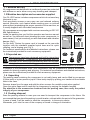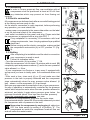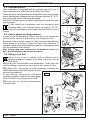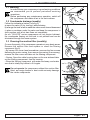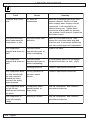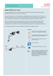
1
FOREWORD How to use this instructions manual This manual is an integral part of your compressor, and shall be kept with it for future reference. Should your compressor be resold, entrust it to the new owner who will obviously need the information contained. Retain this manual in a suitable place and when consulting it, take care of not spoiling it. Before starting the compressor read this manual carefully so as to understand the contents clearly; consult it whenever any doubt arise. This manual contains information useful for your safety. Follow the indications contained in it and perform the recommended procedures which, if not properly observed, could result in damage to equipment or could cause personal injury. Moreover, you will find useful information which will make the use and maintenance of your compressor easier. This manual does not include the spare parts list, which is available by our Authorized Resellers. Should the manual be lost, ask for a new copy. English E-1 SAFETY WARNINGS Symbols used in this manual In order to make evident same special information, the following symbols are used; however you are not relieved from reading the instructions manual carefully. WARNING: It refers to safety instructions to be complied with in order to ensure maximum safety conditions to the operator as well as to people in the working area. SPECIALIZED PERSONNEL: Symbols indicating operations to be carried out by specialized personnel only. IMPORTANT: Symbols at the top of the page refer to whole section Symbols used on the compressor Warning: Shock hazard Warning: Unit is remotely controlled and may start without warning Mandatory: Read the operators instruction Mandatory: When you want to stop the compressor, use the switch located pressure switch body. Never use the main switch or unplug the compressor to power off. What YOU MUST DO: Learn how to stop the compressor suddenly and how to use all controls. Check that mains voltage is the same as the voltage rating stated in the CE plate. Before carrying out any service or routine operation to your compressor, ensure the power has been cut off and all pressure has been released from the tank, so as to prevent any sudden unexpected re-start. After any maintenance operation, make sure all components have been fitted correctly. In order to ensure working safety, before switching on the compressor, always follow the recommended procedures described in the section ''setting up. An operator working close to the compressor should wear ear protection devices. Keep children and animals away from the working area, so as to avoid any injury caused by devices connected to the compressor. Carefully read the instructions of any tool you have installed, especially if a spray gun is used. Provide an automatic circuit breaker for protection against indirect contacts. To this end, remember that the compressor is rated to class I and includes an earth connector. Make sure the shop is well ventilated before you start painting. E-2 English SAFETY WARNINGS What YOU MUST NOT DO: Do not touch the cylinder heads, the cooling fins, and the feed pipe. During operation, because of the high temperature achieved, those parts keep hot for a certain time even after switching off the compressor. Do not leave inflammable, nylon objects, or cloths near the compressor. Do not move the compressor with the tank under pressure. Do not use the compressor with the supply cord damaged or with precarious connection. do not use the compressor in moist or dusty premises. Do not use the compressor in a potential explosive environment. Do not direct the air jet towards people or animals. Do not allow anyone to operate the compressor unless he/she has received correct instructions. Do not operate the compressor without air filter. Do not spray in closed areas or near naked flames. Do not hit the fans with metallic or sharp objects as they could break during operation. Do not connect a hose which has a flow rate lower than that of the compressor to the air outlet cock. Do not use the compressor at temperatures lower than 0°C (temperature range: +5°C / +45°C). Do not alter any safety and adjusting devices. Technical assistance USE ONLY ORIGINAL SPARE PARTS, AVAILABLE AT ALL AUTHORIZED SERVICE CENTRES. IMITATION SPARE PARTS MAY DAMAGE YOUR COMPRESSOR IRREPARABLY. When asking for information or service always quote model, type and serial number of your compressor, which are printed on the label applied on the cover of this manual and on the compressor's nameplate. Product identification The product you have bought is identified by the CE label reproduced on the cover page of this manual and affixed to compressor, including the following data: 1) Manufacturers data 2) CE mark year of manufacture 3) TYPE = compressor name, CODE = compressor code, SERIAL N. = compressor serial number (always indicate this number when requesting service) 4) Air delivery of compressor in (l/min) and (cfm) 5) Max. operating pressure (bar and PSI) compressor noise level in dB(A) 6) Electrical data: power supply voltage (V/ph), frequency (Hz), absorption (A) power (HP and kW), revolutions per minute (Rpm). 7) Other type approvals 1 2 3 4 5 6 7 English E-3 1. MAIN INFORMATIONS 1.1 Machine delivery All compressors are delivered in a cardboard box and are protected with stiffener so as to allow a very easy handling and transport. 1.2 Machine description and accessories supplied Our OILLESS series includes compressors which do not need any lubricants to run. Such peculiarity ensures a very easy use and reduced ordinary service. Moreover, such feature allows working even on inclined plane without jeopardizing the proper operation of the machine, as it usually happens with lubricated compressors. All compressors are equipped with receivers according to EEC 87/ 404 Specifications. Inside the packing box you find the operation and service manual as well as the technical sheet showing the main components, in some cases (if not yet mounted) you also find wheels and vibration damper (fig.1). For the mod. Genius the power cord is housed on the rear side together with the standard supplied spiral hose and its quick coupling, and a blowing gun (Fig.1). For technical specifications and detailed instructions, please see the instructions provided for each accessory equipment. 1.3 Expected use Compressors have been designed and built for intermittent duty applications. Compressors are equipped with an 1 overload cut-out which trips automatically and cuts off power when safety limits are reached. However, we recommend that compressor duty cycle never exceed 50% and continuous operation never exceed 15 minutes. In addition to the pneumatic tools, your compressor may be connected to several accessories suitable for blowing, washing and spraying. For technical specifications and detailed instructions, please see the instructions provided for each accessory equipment. 1.4 Unpacking The packing case containing the compressor is not really heavy and can be lifted by one person (6 litres tank) or by two persons (up to 6 litres tank) simply by putting your hands into the suitable slots in the case. Remove straps from the case and with the pliers remove the metallic points when applied. Open the upper flaps and lift carefully the compressor by seizing the suitable handles Pay attention to the accessories contained into the packing case, then verify the perfect integrity of your compressor. 1.5 Packing disposal Save the packing material in case you ever need to transport the compressor in the future. We recommend that you store the packing in a safe location, at least within the period of the guarantee. In case of need, it will be easier to send the compressor to the service centre. Afterwards, put it into the care of the company or board in charge of elimination. E-4 English 2. SETTING UP 2.1 Positioning In order to ensure proper air flow, rear ventilation grills of compressors shall be positioned at least at 50 cm from any obstacles which may prevent air from flowing out correctly. ON / I OPEN A B 2.2 Electric connection All compressors are delivered only after a succesfull testing period at the factory and are ready to use. As the electric connection is really important, before performing any operation, you must check that: mains power corresponds to the power data written on the label or on the technical sheet of the compressor, wall outlet is suitable for the power cord plug. Please note that the compressor is equipped with a plug type EEC 7 If any adaptation is necessary, in accordance with local voltage requirements, have the plug replaced by a qualified electrician. Before carrying out the electric connection, make sure that the compressor main switch (A) is OFF, position "0" (Fig. 2). CLOSE OFF / 0 E OFF / 0 ON / I A B 2.3 Starting After completing the installation and the electric connection your compressor is ready to work. Follow the indication below: Turn the main switch (A) to position "I" ON . Make the compressor run for about 10 minutes with air cock (B) completely open and pressure reducer (C) set to the max. pressure value allowed, i.e. 8 bar. If your compressor is a Genius or, in any case, if equipped with a snap cock you have to totally open the condensate drain cock (E). After such a time, close cock (A) or (E) and make sure that pressure in the tank is properly delivered and the compressor stops automatically when the max. pressure value allowed (8 bar) - shown on the manometer (D) is achieved. Now you may appreciate the easiness of use of your compressor. Its way of operation is automatically controlled by the pressure switch which stops the motor when the max. pressure allowed is achieved, and starts it again when pressure goes below the minimum threshold (about 2 bar less than the max. pressure). When the compressor runs correctly, you note: a) a whistle of compressed air whenever the motor stops, b) a protracted whistle (about 20-30 seconds) whenever you start the compressor with no pressure in the tank. Never stop the compressor by unplugging it; rather turn OFF the main switch by setting it to position "0". The compressed air inside the compressor head will flow out and will make the restart easier. D C D C E ON / I A OFF / 0 C B D E 2 English E-5 2. SETTING UP 2.4 Overload cutout Your compressor is equipped with an overload cutout (F) (Fig. 3) which operates as a safety device to protect the motor. When the motor overheats because of any fault arisen, the overload cutout automatically releases and cuts off power (position "0", OFF), thus preventing motor from being damaged. Wait a few minutes (about 5) before resetting the device then start working again. If you restart the compressor and the overload cutout releases again, turn the main switch to position "0" OFF, unplug the equipment, and contact any Authorized Service Centre. F F 2.5 How to adjust working pressure In order to use all accessories at their best, see in the manual the rated pressure value of the accessory you are going to use. By means of the pressure reducer (C) (fig,4) you can adjust delivery compressed air pressure. Simply turn the knob clockwise to increase pressure and anticlockwise to reduce it, matching the mark with the pressure value desired. After having used your compressor, set pressure to zero, so as to avoid damaging the pressure reducer. 2.6 Fitting a new tool When you fit a tool or change it with a different one by keeping pressure constant in the tank, you must stop air flow (fig.4). (B1) Slider cock: turn the slider cock downwards. Finally, open the cock by shifting it upwards so as to restore the correct air flow. (B2) Snap cock: disconnect the quick coupling by pushing the cock flange towards the control panel: air flow will stop automatically. 4 Fit the new tool, connect the cock quick coupling and push it towards the control panel so as to restore the compressed air flow. (B3) Line cock: turn the lever anticlockwise to stop air flow. B1 F 3 C OPEN B3 D OPEN CLOSE CLOSE C D B2 D C E-6 English 3. MAINTENANCE 3.1 Warning In order to keep your compressor in good working conditions we recommend you to perform periodical servicing operations. Before performing any maintenance operation, switch off the compressor and make all air in the tank release. E 3.2 Condensate drainage (weekly) Follow the indications below ( see fig.5): a) open the valve (E) by turning it anticlockwise, b) arrange the tank so as to make the valve mouth turned downward c) place a container under the valve and keep the compressor in such position until all air has flown out completely. As our "OILLESS" series compressors do not require lubricant, the condensate flowing out the tank is not polluted and can be eliminated through the sewer system. E 3.3 Cleaning the suction filter (monthly) Or more frequently, if the compressor operates in very dusty areas. Remove the suction filter and replace or clean the filtering component (fig.6). By means of a cross head screwdriver unscrew the four screws fastening the motor casing, then remove the casing (if necessary), remove the filter cover and take out the filtering component. Genius: Open the cable housing door on the rear sideand take out the filtering component from its housing. Rinse the filtering component with water and soap, and make sure that is totally dry before to fit it again. E 5 Do not operate the compressor without the suction filter fitted, as foreign bodies or dust could seriously damage the inside components. 6 English E-7 4. TROUBLESHOOTING Fault C au se R emedy Pressure drop i n the tank. Ai r leaks at connecti ons Make the compressor get to the max. pressure allowed. Swi tch i t off and brush a soapy water soluti on onto all connecti ons. Look carefully for ai r bubbles flowi ng out. Ti ghten those connecti ons where leaks are present. If the problem i s sti ll present, contact the after-sales servi ce. The pressure swi tch valve leaks when the compressor i s i dle. Non-return valve seal defecti ve. Make ai r i n the tank flow out. Then remove the non-return valve plug and clean the seat. If necessary replace the seal, then mount agai n all components. The compressor stopped and does not start. Overload cutout operated because of motor overheati ng. Replace the valve. The compressor stopped and does not start. Overload cutout operated because of motor overheati ng. By the pressure swi tch cut off voltage and press the button to start (fi g.3) Wi ndi ng bornt out. C ontact a speci ali sed techni ci an. The compressor does not stop eventhough the max. pressure allowed has been reached; the safety valve operates. Wrong operati on or pressure swi tch broken. C ontact a speci ali sed techni ci an. The compressor does not get the set pressure and oveheats too much C ompressor head gasket broken or valve faulty Stop the compressor and contact a speci ali zed techni ci an The compressor i s noi sy wi th metalli c clangs Beari ng or sei zure Stop the compressor and contact a speci ali zed techni ci an E-8 English