1
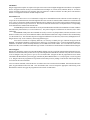
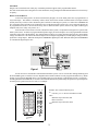
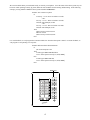
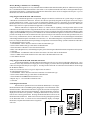
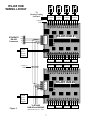
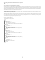
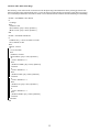
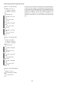
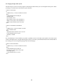
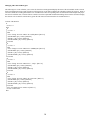
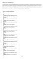
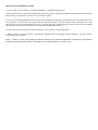
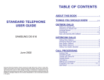
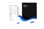
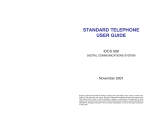
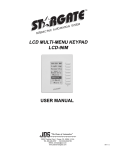
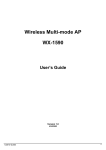
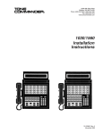
APPLICATION NOTES
LIGHTING
Stargate supports the complete X-10 protocol for power line carrier control of lights and appliances and other X-10 compatible
devices. It supports formats used by several manufacturers including X-10, Leviton, PCS, Smartlinc, RCS, etc. In order to
issue X-10 signals to the power line, Stargate's "PLI" port connects to a TW523 or PSC05 Two-Way Power Line Interface
module via a supplied 4-conductor modular telephone cable.
Preset Dim Level
A Preset Dim or Preset Level command is a single X-10 command that instructs a dimmer switch or module to go
to a specific level (rather than start from full brightness then issue a stream of continuous dim commands to reach the desired
level). This is a much more reliable method of dimming since it minimizes X-10 traffic on the powerline and does not rely
on an external processor to keep track of levels. There are two different formats used to accomplish Preset Level depending
on the manufacturer, standard and extended code.
STANDARD preset dim commands are used by PCS and Smartlinc and follow the standard X-10 format of address
data followed by function data (A-1 A-Preset Dim 97%). The protocol supports 32 different levels from 0% (off) to 100%
(full bright).
EXTENDED CODE preset dim commands are used by X-10 two-way lamp modules (LM-14A) and some Leviton
dimmer switches (6381, 6343) and combine the address data and function data into a single extended code command string
(A-1 Preset Dim 97%). The extended code protocol supports 64 different levels from 0% (off) to 100% (full bright) however
Stargate utilizes only 32 for consistency when using different types.
Since the two formats are completely different, it is necessary to identify the type of dimmer being used in the
DEFINE - X10 DEVICE database so Stargate knows which type of command to issue. For PCS and Smartlinc dimmers,
standard X-10 dimmer switches and lamp modules, select LAMP in the TYPE column. For X-10 LM-14A's and Leviton
dimmer switches, select LAMP EXCODE in the type column. Click APPLY to download the X-10 database data to Stargate.
Lutron Support
Stargate also has built-in support for Lutron HomeWorks lighting systems via ASCII commands through an RS-232 port.
Once the Lutron HomeWorks system has been set up and configured, the HomeWorks controller com port can be connected
to one of Stargate's com ports (port 2 or port 3) via a serial data cable. Stargate can then be programmed to issue ASCII
commands to the HomeWorks system to trigger (simulate) any HomeWorks button (1-17) on any keypad (1-16) on any panel
(1-8). Stargate can also be programmed to respond to Lutron button presses by adding events based on ASCII input strings
received from the Lutron controller.
To issue a Lutron command, select ASCII OUT as a Then Action of an event then click LUTRON. Select the desired Lutron
panel, keypad and button then click OK. Once downloaded, this event will output the appropriate ASCII string to the
HomeWorks controller to trigger the programmed Lutron action for that button.
2
SECURITY
Stargate can be interfaced with virtully any wired alarm panel that supports basic programmable features.
The most common functions to integrate are remote arm/disarm, energy management and automation based on room activity/
occupancy.
Remote Arm and Disarm
To allow the alarm panel to be armed or disarmed by Stargate, one of the alarm panel zones is programmed as a
"keyswitch input." This enables a momentary contact closure between the common terminal and the zone input terminal
(usually from a key switch) to arm or disarm the panel. Instead of connecting a keyswitch, we connect the COMMON and
N.O. (Normally Open) terminals of one of Stargate's relays to the alarm panel keyswitch zone. Once connected, Stargate can
be programmed to activate or de-activate the relay (arm or disarm the alarm system) based on any input (LCD Keypad,
telephone code, time of day, away macro, etc.).
Since the same contact closure will arm or disarm the alarm system, it is important for Stargate to keep track of the
alarm system's status. To do this we program the alarm panel to supply an "Armed Output" via a set of programmable terminals
(sometimes referred to as the PGM lug). The Armed Output provides a low voltage when the alarm system is armed and no
voltage when disarmed. We connect the Armed Output to one of Stargate's Digital Inputs (with the jumper settings in the left
position for "voltage input"). When the alarm panel is ARMED the digital input is ON. When the alarm panel is DISARMED
(or CLEAR) the digital input is OFF.
Figure 1
Events can now be constructed to arm and disarm the alarm system. First we want to allow arming/disarming from
the LCD-96M Keypads. To do this we use the "DigitPad" menu which resembles a security keypad with numeric keys. When
a button is pressed on the DigitPad menu, a corresponding signal is sent to Stargate via the RS-485 network. Using the IF LCD Keypad function in WinEVM, we create an event to turn on and off a relay momentarily in response to a specific sequence
of button presses (password or access code). For example:
EVENT: Arm / Disarm Alarm System
If
LCD Seq: '1 2 3 4' Received within 6 seconds
Then
(RELAY: Keyswitch zone) ON
DELAY 0:00:01
(RELAY: Keyswitch zone) OFF
End
3
We can also add the ability to arm/disarm locally or remotely via telephone. Since the status of the alarm system may not
be known when operating remotely by phone, different codes should be used for arming and disarming. In the following
example, pressing 1-2-3-4-* arms the alarm system and 1-2-3-4-# disarms it.
EVENT: Arm / Disarm via phone
If
LCD Seq: '1 2 3 4' Received within 6 seconds
- OR Tel Seq: '1 2 3 4 *' Received within 6 seconds
and (DI: Armed Output) is OFF
- OR Tel Seq: '1 2 3 4 #' Received within 6 seconds
and (DI: Armed Output) is ON
Then
(RELAY: Keyswitch zone) ON
DELAY 0:00:01
(RELAY: Keyswitch zone) OFF
End
For visual feedback, we will program the red LED to blink slow when the alarm panel is armed. For audio feedback, we
will program a corresponding voice response.
EVENT: Red LED Alarm Status Indication
If
(DI: Armed Output) is ON
Then
LCD Keypad: RED LED Blink Slow
Voice: Alarm System Armed [CO, ICM, SPKR]
Else
LCD Keypad: RED LED OFF
Voice: Alarm System Armed [CO, ICM, SPKR]
End
RED LED
4
Energy Management/Automation based on Occupancy
Another useful function is to manage lighting and heating/cooling based on whether or not the room or area is occupied.
Motion detectors that are used to sense someone's presence in a room can also be used to control lights in that room. This not
only provides the convenience of hands-free automated lighting, but allows lights to be programmed to turn off (or dim to a low
level) after a specified delay time, thereby saving energy. Likewise, multi-zone heating/cooling systems can be controlled by the
same motion detectors, allowing management of heating and cooling based on occupancy.
For automated lighting, there are several conditions to consider. We want the lights to come on as someone enters the
room only if the room is dark, and go off when the room is no longer occupied. Since we are using a motion sensor as a trigger,
we must also allow for instances when the room is occupied but there is no motion, such as when a person is reading, watching
tv or sleeping.
One method of programming is to turn the light on full brightness (preset level 100%) and load/start a 10 minute timer
when motion is detected between sunset and sunrise. For fastest possible response, we create a Fast Event triggered by the motion
sensor. When the timer expires, dim the light slightly (preset level 90%) and load/start a 5 minute timer. When the 5 minute timer
expires, turn off the light. This way, when you enter the room, the light comes on full. If you remain still for 10 minutes (reading
or watching tv), rather than turn off and leave you in the dark, the light will dim slightly to warn you know there are 5 minutes
remaining until it turns off. You can then make any motion (wave your hand) to retrigger the motion sensor 10 minute timer which
returns the light to 100%.
FASTEVENT: [ DI:Motion Sensor Goes OFF]
Then
If
Time is Dark (after SunSet, before SunRise)
Then
X10: A-1 Light PRE-Set Level 100%
(T:LIGHT 1) LOAD with 0:10:00
(T:LIGHT 2) STOP
Nest End
End
[
EVENT: Light Timer 1 Expiring
If
(T:LIGHT 1) is Expiring
and X10:A-1 Light is ON
Then
X10: A-1 Light PRE-Set Level 90 %
(T:LIGHT2) LOAD with 0:05:00
End
EVENT: Light Timer 2 Expiring
If
(T:LIGHT 2) is Expiring
Then
X10: A-1 Light OFF
End
Figure 2
EVENT: Light Off
If
(XSEQ: A-1 A-OFF) Received within 3 seconds
Then
(T:LIGHT 1) STOP
(T:LIGHT 2) STOP
End
NOTE: When connecting a motion sensor to both Stargate (digital input) and a security zone, place the digital input jumpers in
the "Voltage" or left position and connect the sensor contacts, alarm zone and digital input in a series circuit as shown in figure
2. If an end-of-line (E.O.L.) resistor is required, change it to a value 470 ohms less to accommodate the added resistance of the
digital input. (If the E.O.L. is 1000 ohms, change it to 560 ohms, the closest standard resistor value.) If possible, program the
zone for "No Resistor Required" to provide the maximum current through the zone loop. If the alarm panel has separate relays
that can be programmed to "follow" the status of each security zone, connect each relay to a Stargate digital input and place the
digital input jumpers in the "Switch" or right position.
5
HVAC (Heating, Ventilation, Air Conditioning)
Stargate has built-in support for two-way communication with thermostats manufactured by RCS, Inc. and Enerzone Systems,
Inc. Communication with RCS thermostats is done either via X-10 (thermostat model TX-15B) or via Stargate's RS-485 port
(thermostat model TR15). Communication with Enerzone thermostats is done via one of Stargate's RS-232 ports. Up to 16
thermostat zones can be monitored and controlled.
Using Stargate with the RCS TX-15B Thermostat
When a hardwired approach is not practical, Stargate can interface with the HVAC system using X-10 signals to
communicate to and from the thermostat. The RCS TX-15B was specifically designed for this purpose and can be setup to
provide reliable HVAC control. Up to 16 zones are supported by Stargate, however, when using X-10 communication for
thermostat control, it is wise to limit the number of zones in the system to minimize X-10 traffic on the power line. When more
than a couple zones are required, a hardwired approach is recommended.
Each TX-15B utilizes a complete X-10 "House" or "Letter" code for signalling. Four dip switches on the TX-15B
control unit circuit board are used to assign the the House code. Other X-10 devices in the system must be set to different house
codes to avoid unwanted interaction. For maximum control, it is best to setup the TX-15B to use DECODE TABLE #1 which
employs the STANDARD X-10 preset level command set for control and acknowledgement. The Preset Level command set
provides 512 unique X-10 codes for each House code (32 preset levels per Unit code times 16 Unit codes per House code). For
true two-way communication, the TX-15B monitors Unit codes 1 - 5 for commands received from Stargate and transmits
acknowledgements and response commands over Unit codes 6 - 16. This enables Stargate to verify that HVAC commands have
been received by the thermostat and act upon changes in temperature or thermostat settings. (See RCS Advanced Code Table)
To setup Stargate for the TX-15B:
1. Click DEFINE - HVAC and select "RCS TX-15B" for Thermostat Type.
2. Select a Zone number and type a Zone Name for identification.
3. Select the House Code that is reserved for the thermostat.
4. In the "TX15-B Options" box, set the Polling Frequency (how often Stargate reads the thermostat's temperature and set point).
5. Click OK.
6. Click DEFINE - X10 DEVICE and scroll to the X10 House Code letter used for the thermostat.
7. Select "LAMP" in the TYPE column for all 16 unit codes of the thermostat House code.
8. Click APPLY then OK.
Using Stargate with the RCS TR-15 RS-485 Thermostat
For maximum reliability, the TR-15 RS-485 thermostat provides two-way control via Stargate's RS-485 port. Up to
16 TR-15's can be daisy-chained over a single pair of wires (catagory-5) or home run to an optional RS-485 hub which in turn
connects to Stargate's RS-485 port (see Figure 3). Four dip switches on the TR-15 control unit circuit board are used to assign
the the RS-485 address.
NOTE: Each thermostat must be assigned a different RS-485 address.
To setup Stargate for the TR-15:
1. Click DEFINE - HVAC and select "RCS TR-15 RS-485" for Thermostat Type.
2. Select a Zone number and type a Zone Name for identification.
3. Select the RS-485 ADDRESS the thermostat is set to.
4. Repeat steps 2 - 3 for each TR-15 Thermosat zone.
5. Click OK.
Controlling the Thermostat
Once the HVAC parameters have been defined in WinEVM, we can assign a
thermostat button to the LCD-96M Keypad by dragging the word "Thermostat" to the
desired menu line. When downloaded to the keypad, the menu line will display the
thermostat location name and current temperature. Outside temperature can also be
displayed on the menu line (optional). If multiple thermostats are used, select the
nearest zone to the keypad location. Pressing the thermostat button will access the
thermostat menu for that zone. Other zones can be accessed by pressing the top button
of the thermostat menu. For direct access and simultaneous display of multiple
thermostats, a separate menu button can be assigned for
each zone.
ZONE 1
IN 76 OUT 65
ZONE 2
72
ZONE 3
75
ZONE 4
68
6
RS-485 HUB
WIRING LAYOUT
To
Heating/Cooling
System #1
TR-15 #1
Control
Unit
Catagory-5
Cable
STARGATE
RS-485
Connector
TR-15 #2
Control
Unit
TR-15 #3
Control
Unit
TR-15 #4
Control
Unit
RS-485 HUB #1
+12v
GND
B+
A-
12vdc
@1A
Power
Supply
RS-485
Device #5
RS-485
Device #6
RS-485
Device #7
RS-485
Device #8
RS-485
RS-485
RS-485
RS-485
Device #9 Device #10 Device #11 Device #12
Catagory-5
Cable
RS-485 HUB #2
12vdc
@1A
Power
Supply
Figure 3
To RS-485
HUB #3 and HUB #4
RS-485
RS-485
RS-485
RS-485
Device #13 Device #14 Device #15 Device #16
(RS-485 Device #17 - #32)
7
HVAC cont'd
fThermostats can also be monitored and controlled from any local or remote telephone. There are several ways to program this feature
depending on the amount of control required. In the following example, pressing the code H-V-A-C-* (4-8-2-2-*) triggers an event
that voices the current temperature and setpoint, then prompts the user to press subsequent digits for more options.
EVENT: HVAC*
If
TelePhone Seq:'4822*' Received within 6 seconds
Then
(F:HVAC) SET
Voice:THE TEMPERAT IS Zone1 Temperature DEGREES SET Zone1 Setpoint DEGREES [CO,ICM]
Voice:TO SET TEMPERAT PRESS 1 [CO,ICM]
Voice:FOR COOL MODE PRESS C O [CO,ICM]
Voice:FOR HEATING MODE PRESS H E [CO,ICM]
Voice:FOR AUTOMATI MODE PRESS A U [CO,ICM]
Voice:FOR OFF MODE PRESS 0 0 [CO,ICM]
Voice:FOR FAN ON PRESS F A STAR [CO,ICM]
Voice:FOR FAN OFF PRESS F A POUND [CO,ICM]
Voice:TO LEAVE THIS MENU PRESS POUND 0 [CO,ICM]
End
EVENT: HVAC SELECT
If
(F:HVAC) is SET
Then
If
TelePhone Seq:'1' Received within 2 seconds
Then
Voice:ENTER TEMPERAT FOLLOWBY POUND [CO,ICM]
TouchTone to user_VAR SYNC
(HVAC:Zone1) Load Setpoint with value in user_VAR
Clear TouchTone Input Buffer
Nest End
If
TelePhone Seq:'26' Received within 3 seconds
Then
(HVAC:Zone1) COOL Mode
Voice:COOL MODE [CO,ICM]
Nest End
If
TelePhone Seq:'43' Received within 3 seconds
Then
(HVAC:Zone1) HEAT Mode
Voice:HEATING MODE [CO,ICM]
Nest End
If
TelePhone Seq:'28' Received within 3 seconds
Then
(HVAC:Zone1) AUTO Mode
Voice:AUTOMATI MODE [CO,ICM]
Nest End
If
TelePhone Seq:'00' Received within 3 seconds
Then
(HVAC:Zone1) OFF Mode
Voice:OFF MODE [CO,ICM]
Nest End
8
If
TelePhone Seq:'32*' Received within 3 seconds
Then
(HVAC:Zone1) Fan ON
Voice:FAN ON [CO,ICM]
Nest End
If
TelePhone Seq:'32#' Received within 3 seconds
Then
(HVAC:Zone1) Fan OFF
Voice:FAN OFF [CO,ICM]
Nest End
If
TelePhone Seq:'#0' Received within 3 seconds
or TelePhone Seq:'+' Received within 2 seconds
Then
(F:HVAC) CLEAR
Voice:BDRINGGG [CO,ICM]
Nest End
End
AUDIO/VIDEO/HOME THEATER
To integrate audio and video components into the system, an optional IR-XP2 InfraRed Xpander is connected to Stargate's "AUX"
port. The IR-Xpander learns and stores all the infrared (IR) commands from each audio/video component's remote control. Once
the IR commands have been learned into the IR-Xpander, Stargate can be programmed to control any audio/video function via
LCD Keypad, LED Keypad, telephone, X-10, or by time or event.
IR-XPANDER
TO STARGATE,
"AUX" JACK
POWER IN RS-485
12VDC
500mA
RS232
AUX
EMITTER OUTPUTS
1
2
3
4
POWER
SENSORS
IR EMITTERS
DATA CABLE
DUAL IR EMITTER
STEP 1: Learning IR Commands Into The IR-Xpander (refer to InfraRed Xpander User Manual)
STEP 2: Creating Audio And Video Menus On The LCD Keypad
The LCD-96M Keypad provdes an easy user interface for controling most audio and video control functions such as volume up/
down, channel up/down, input selection, mute, etc. Separate menus can be defined to navigate through the various audio and video
components. To define a menu:
1) Click DEFINE - LCD KEYPAD then select the desired keypad address.
2) Click SELECT then double-click the desired menu number.
3) Click and Drag "Then Action" to the desired menu line.
4) Select "IR" from the then action list.
5) Select the desired IR command and emitter output(s).
6) Type the label (text) for the button or click "Bitmap" then select the desired icon to represent the button and click OK.
7) Repeat steps 3 - 6 to complete the menu.
HBO CNN
ABC
9
NBC
Integrating Other Functions With Audio/Video Components
Using Variables To Control Input Source Settings
Successive presses of a single button can be programmed to select the various input sources of a stereo receiver (tuner, tape, cd,
video). Each time the button is pressed, it triggers a Then Action to increment the "Source" variable. Each time the Source Variable
changes value the SOURCE SELECT event (below) instructs Stargate to issue the appropriate IR command (via the IR-Xpander)
and change the menu line text to identify the selected source.
Another method is to use separate buttons for each source input. Pressing a button triggers a Then Action to load the "Source"
variable with the corresponding value.
With either method, Stargate can keep track of the input source by the value of the Source Variable provided the receiver input
is not changed at the receiver or via IR remote. If the source does get changed at the receiver or via IR remote, pressing a source
select button on a keypad will put the system back in sync.
EVENT: SOURCE SELECT
If
(V:SOURCE) Changes Value
Then
If
(V:SOURCE) = 0
Then
(IR:TUNER ) play 1 time(s) [1]
LCD: Change Text Item 3 Menu 16 to 'Tuner' [KP:# 1]
Nest End
If
(V:SOURCE) = 1
Then
(IR:TAPE ) play 1 time(s) [1]
LCD: Change Text Item 3 Menu 16 to 'Tape' [KP:# 1]
Nest End
If
(V:SOURCE) = 2
Then
(IR:CD ) play 1 time(s) [1]
LCD: Change Text Item 3 Menu 16 to 'CD' [KP:# 1]
Nest End
If
(V:SOURCE) = 3
Then
(IR:VIDEO ) play 1 time(s) [1]
LCD: Change Text Item 3 Menu 16 to 'Video' [KP:# 1]
Nest End
If
(V:SOURCE) >= 4
Then
(V:SOURCE) LOAD with 0
Nest End
End
10
Automatic Mute When Phone Rings
The following events will mute the TV and stereo when the phone rings and unmute them when you hang up after the call.
Instead of issuing a mute command to the stereo, we switch it to the AUX input to allow it to announce Caller ID (see next page).
A 2-second delay is added to the 'ON-Hook Un-Mute' event to maintain the mute condition when hookflashing for Call Waiting.
EVENT: INCOMING CALL MUTE
If
CO: Ring 1
Then
(F:MUTE) SET
(IR:TV MUTE ) play 1 time(s) [Emitter1]
(IR:RCV AUX ) play 1 time(s) [Emitter1]
End
EVENT: ON-HOOK UN-MUTE
If
TelePhone Seq:’+’ Received within 2 seconds
and (F:MUTE) is SET
Then
DELAY 0:00:02
If
CO: Is ON Hook
Then
(F:MUTE) CLEAR
(IR:TV MUTE ) play 1 time(s) [Emitter1]
If
(V:RCV SOURCE) = 0
Then
(IR:RCV TUNER ) play 1 time(s) [Emitter1]
Nest End
If
(V:RCV SOURCE) = 1
Then
(IR:RCV TAPE ) play 1 time(s) [Emitter1]
Nest End
If
(V:RCV SOURCE) = 2
Then
(IR:RCV CD ) play 1 time(s) [Emitter1]
Nest End
If
(V:RCV SOURCE) = 3
Then
(IR:RCV VIDEO ) play 1 time(s) [Emitter1]
Nest End
Nest End
End
11
Announcing Caller ID Through Audio System
EVENT: CALLER ID LIST 1
If
CallerID: ???1111111
or CallerID: ???2222222
or CallerID: ???3333333
Then
(F:CallerID) SET
If
CallerID: ???1111111
Then
Voice: Moe [Line]
Nest End
If
CallerID: 2222222222
Then
Voice: Larry [Line]
Nest End
If
CallerID: ???3333333
Then
Voice: Curly [Line]
Nest End
End
The following events check the Caller ID of each incoming call and play
a unique User Voice Response for each number in the Caller ID List
events. Since there is a limit to the number of If - CallerID lines that can
be placed in a single event (about 20), separate events have been
created, each containing a portion of the CallerID numbers to be
announced by a unique User Voice Response. Calls that are not
included in a Caller ID List event will be announced by phone number
only.
EVENT: CALLER ID LIST 2
If
CallerID: ???4444444
or CallerID: ???5555555
or CallerID: ???6666666
Then
(F:CallerID) SET
If
CallerID: ???4444444
Then
Voice: Peter [Line]
Nest End
If
CallerID: ???5555555
Then
Voice: Paul [Line]
Nest End
If
CallerID: ???6666666
Then
Voice: Mary [Line]
Nest End
End
EVENT: CALLER ID OTHER
If
CallerID: ??????????
and (F:CallerID) is CLEAR
Then
Voice:<CID> [Line]
End
12
Voice Paging Through Audio System
The following two events will switch your phone to the ICM port and broadcast your voice through the audio system. When
you hang up, it switches back to the normal CO port connection.
EVENT: LIVE PAGE
If
TelePhone Seq:’^7*’ Received within 4 seconds
Then
Connect PHONE port to ICM port
(F:PAGE) SET
(F:TV MUTE) SET
(IR:TV MUTE ) play 1 time(s) [Emitter1]
(IR:RCV AUX ) play 1 time(s) [Emitter1]
Audio:Connect ICM In to Line Level Out
End
EVENT: ON-HOOK CLEAR PAGE
If
TelePhone Seq:’+’ Received within 2 seconds
and (F:PAGE) is SET
Then
Audio:Disconnect ICM In to Line Level Out
Connect PHONE port to CO port
(F:PAGE) CLEAR
End
If live broadcasting live causes feedback, your phone is probably too close to the audio system speakers or the audio system
volume is turned up too loud. Using the following Delayed Page event will let you broadcast announcements without feedback
by recording your voice message then playing it back when you hang up.
EVENT: DELAYED PAGE
If
TelePhone Seq:’^8*’ Received within 4 seconds
Then
Connect PHONE port to ICM port
Record:’Page’ from ICM for 10 seconds
Voice:Page [Line]
Connect PHONE port to CO port
End
13
Managing CD's With LCD Keypad
The following two events will allow you to select cd's from the LCD Keypad and display the name of the selected disk on the cd menu.
Since CD management is not a built-in function of the keypad, an event must be added to the schedule to manage cd selection. When a
selection is made, the LCD Keypad loads the "CD" Variable with a value corresponding to the cd's slot number in the multiple disk player.
For each CD Variable value, a nested if-then is created to isuue the required IR commands and change the text on the cd menu to display
the selection. The event then switches the keypad to the CD menu screen and loads the CD Variable back to 0.
EVENT: CD SELECT
If
(V:CD) > 0
Then
If
(V:CD) = 1
Then
LCD: Change Text Line 1 Menu 18 to 'AbbeyRoad ' [KP:# 13]
(IR:CD DISK ) play 1 time(s) [Emitter1]
(IR:CD 1 ) play 1 time(s) [Emitter1]
(IR:CD ENTER ) play 1 time(s) [Emitter1]
Nest End
If
(V:CD) = 2
Then
LCD: Change Text Line 1 Menu 18 to 'HardDaysNi' [KP:# 13]
(IR:CD DISK ) play 1 time(s) [Emitter1]
(IR:CD 2 ) play 1 time(s) [Emitter1]
(IR:CD ENTER ) play 1 time(s) [Emitter1]
Nest End
If
(V:CD) = 3
Then
LCD: Change Text Line 1 Menu 18 to ' Help! ' [KP:# 13]
(IR:CD DISK ) play 1 time(s) [Emitter1]
(IR:CD 3 ) play 1 time(s) [Emitter1]
(IR:CD ENTER ) play 1 time(s) [Emitter1]
Nest End
If
(V:CD) = 4
Then
LCD: Change Text Line 1 Menu 18 to 'Let It Be ' [KP:# 13]
(IR:CD DISK ) play 1 time(s) [Emitter1]
(IR:CD 4 ) play 1 time(s) [Emitter1]
(IR:CD ENTER ) play 1 time(s) [Emitter1]
Nest End
LCD: Goto Menu Screen = Menu 18 [KP:# 13]
(V:CD) LOAD with 0
End
14
Managing CD's With LCD Keypad
A simpler method to implement is to use the TelePad menu to enter the disk slot number directly. This does not provide a listing of the CD
titles as with the previous method, but allows CDs to be added to the player without having to modify the schedule or LCD Keypad CD menus.
In this case, the user must know the slot number for the desired disk selection. Note: Button presses on the TelePad menu are treated the
same as touchtones over the ICM line. Any event programmed to respond to touchtone sequences can be controlled via the TelePad as well
as X-10 devices (when "90 codes" or "160 codes" is selected in the Define - Telephone field).
EVENT: CD SELECT BY TELEPAD
If
ICM: Is ON Hook
Then
If
TelePhone Seq:'1' Received within 2 seconds
Then
(IR:CD1 1 ) play 1 time(s) [Emitter1]
Nest End
If
TelePhone Seq:'2' Received within 2 seconds
Then
(IR:CD1 2 ) play 1 time(s) [Emitter1]
Nest End
If
TelePhone Seq:'3' Received within 2 seconds
Then
(IR:CD1 3 ) play 1 time(s) [Emitter1]
Nest End
If
TelePhone Seq:'4' Received within 2 seconds
Then
(IR:CD1 4 ) play 1 time(s) [Emitter1]
Nest End
If
TelePhone Seq:'5' Received within 2 seconds
Then
(IR:CD1 5 ) play 1 time(s) [Emitter1]
Nest End
If
TelePhone Seq:'6' Received within 2 seconds
Then
(IR:CD1 6 ) play 1 time(s) [Emitter1]
Nest End
If
TelePhone Seq:'7' Received within 2 seconds
Then
(IR:CD1 7 ) play 1 time(s) [Emitter1]
Nest End
If
TelePhone Seq:'8' Received within 2 seconds
Then
(IR:CD1 8 ) play 1 time(s) [Emitter1]
Nest End
If
TelePhone Seq:'9' Received within 2 seconds
Then
(IR:CD1 9 ) play 1 time(s) [Emitter1]
Nest End
If
TelePhone Seq:'0' Received within 2 seconds
Then
(IR:CD1 10 ) play 1 time(s) [Emitter1]
Nest End
If
TelePhone Seq:'#' Received within 2 seconds
Then
(IR:CD1 ENTER ) play 1 time(s) [Emitter1]
Nest End
End
15
DEFAULT INTERCOM
In many cases it is more convenient to have Stargate default to the INTERCOM rather than the CO line. Selecting ICM under Define Telephone Setup - Phone Output Default will cause all phones to be connected to the ICM port by default. Dialing "9" will switch the user
to the outside line (CO). When this setup is used, it is important to note that all phones connected to Stargate's "PHONE" port will not ring
since they are normally not connected to the CO line. The following events will switch Stargate's "PHONE" port to the CO line when the
line rings and switch back to the ICM line when the phone hangs up after a call. Additional events are used to accomodate abandoned calls
(the caller hangs up before you or Stargate answers the call). The OFF-HOOK AUTO SWITCH event (optional) automatically switches
an off-hook phone to the CO line after 3 seconds if no touchtone is pressed. This is useful for those who are not familiar with the system
and don't know to dial "9" for the outside line. If any touchtone other than "9" is pressed after going off-hook, Stargate remains connected
to the ICM line.
EVENT: DEFAULT ICM RING
If
CO: Ring 1
or CO: Ring 2
or CO: Ring 3
or CO: Ring 4
Then
Connect PHONE port to CO port
(T:RING) LOAD with 0:00:08
End
EVENT: DEFAULT ICM RESET
If
TelePhone Seq:'+' Received within 2 seconds
Then
DELAY 0:00:02
If
CO: Is ON Hook
Then
Connect PHONE port to ICM port
Nest End
End
EVENT: ABANDONED CALL
If
(T:RING) is Expiring
and CO: Is ON Hook
Then
Connect PHONE port to ICM port
End
EVENT: OFF-HOOK - AUTO SWITCH
If
(T:RING) is Not Running
Then
If
ICM: Is OFF Hook
Then
(T:DIAL TONE) LOAD with 0:00:03
Nest End
If
TelePhone Seq:’^?’ Received within 4 seconds
Then
(T:DIAL TONE) STOP
Nest End
If
(T:DIAL TONE) is Expiring
Then
Connect PHONE port to CO port
Nest End
If
ICM: Is ON Hook
and (T:DIAL TONE) is Running
Then
(T:DIAL TONE) STOP
Nest End
End
16
CREATING CUSTOMER DATABASES
1. Create a folder for each customer (C:\STARGATE\SMITH, C:\STARGATE\JONES, etc.)
2. Place a shortcut icon on your desktop for WinEVM. (From Windows Explorer, right click on the WinEVM application icon in the Stargate
folder and drag it onto the desktop. Then click "Create Shortcut Here.")
3. Create a copy of the WinEVM shortcut icon for each customer. (Right click and drag the original shortcut icon to the sideand let go. Then
click "Copy Here." For each copied icon, right click the icon and select "Rename." Type the customer's name to identify the icon. Then
right click the copied icon again and select "Properties." Select the "Shortcut" tab and change the "Start in" field to the corresponding
customer folder (eg: change C:\STARGATE to C:\STARGATE\SMITH) then click OK.
4. Copy all the customer's database files (.dbf) and schedules (.sch) into their corresponding folders.
5. When you click on a customer shortcut, it will bring up WinEVM with the corresponding customer's databases. Click File - Open to
access the customer's schedule.
NOTE: ALWAYS CLOSE THE SCHEDULE BEFORE EXITING THE WINEVM PROGRAM TO PREVENT THE WRONG
SCHEDULE FROM SHOWING WHEN A DIFFERENT CUSTOMER SHORTCUT IS SELECTED.