1
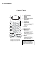
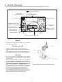
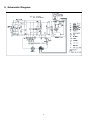
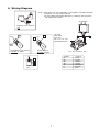
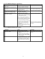
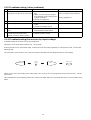
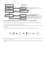
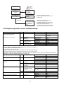
HAD0608002C2
Microwave Oven
NN-A574SBBTQ
NN-A554WBBTQ
NN-A524MBBTQ
Power source
230-240VAC Single Phase 50Hz
Power requirements
Microwave 1180W
Grill 1380W
Convection 1390W
Micro / Grill Combi 2380W
Micro / Conv Combi 2390W
Output (IEC60705)
Microwave 1000W
Grill 1300W
Convection 1300W
Microwave frequency
2450 Mhz
Timer
99 min 99 second
Oven cavity size
27L
Outside dimensions
510mm(W) x 390mm(D) X 305MM (H)
Inside dimensions
359mm(W) X 352mm(D) x 217mm(H)
Weight
13Kg
Specifications subject to change without notice
! WARNING
This service information is designed for experienced repair technicians only and is not designed for use by the
general public. It does not contain warnings or cautions to advise non-technical individuals of potential dangers
in attempting to service a product. Products powered by electricity must be serviced or repaired only by experienced proffesional technicians. Any attempt to service or repair the product or products dealt with this service
information by anyone else could result in serious injury or death.
IMPORTANT SAFETY NOTICE
There are special components used in this equipment which are important for safety. These parts are marked
by (!) in the schematic diagrams, circuit board diagrams, exploded views and replacement parts lists. It is
essential that these critical parts are replaced with parts specified by the manufacturer, preventing shock, fire
or other hazards. Do not modify the original design without permission from the manufacturer.
1 Contents
1
Contents . . . . . . . . . . . . . . . . . . . . . . . . . . . . . . . . . . . . . . . . . . . . . . . . . . . . . . . . . . 2
2
Feature Chart . . . . . . . . . . . . . . . . . . . . . . . . . . . . . . . . . . . . . . . . . . . . . . . . . . . . . . 3
3
Control Panel . . . . . . . . . . . . . . . . . . . . . . . . . . . . . . . . . . . . . . . . . . . . . . . . . . . . . . 4
4
Inverter Warnings . . . . . . . . . . . . . . . . . . . . . . . . . . . . . . . . . . . . . . . . . . . . . . . . . . 5
5
Oven Schematic . . . . . . . . . . . . . . . . . . . . . . . . . . . . . . . . . . . . . . . . . . . . . . . . . . . . 6
6
Wiring Diagram . . . . . . . . . . . . . . . . . . . . . . . . . . . . . . . . . . . . . . . . . . . . . . . . . . . . 7
7
Description of Operation . . . . . . . . . . . . . . . . . . . . . . . . . . . . . . . . . . . . . . . . . . . . . 8
8
Cautions when Troubleshooting. . . . . . . . . . . . . . . . . . . . . . . . . . . . . . . . . . . . . . . . 9
9
Part Replacement Procedure . . . . . . . . . . . . . . . . . . . . . . . . . . . . . . . . . . . . . . . . . . 12
10 Component Test Procedure . . . . . . . . . . . . . . . . . . . . . . . . . . . . . . . . . . . . . . . . . . . 15
11 Measurements and Adjustments . . . . . . . . . . . . . . . . . . . . . . . . . . . . . . . . . . . . . . . 17
12 Troubleshooting Guide . . . . . . . . . . . . . . . . . . . . . . . . . . . . . . . . . . . . . . . . . . . . . . . 18
13 Parts List . . . . . . . . . . . . . . . . . . . . . . . . . . . . . . . . . . . . . . . . . . . . . . . . . . . . . . . . . 24
14 Exploded View . . . . . . . . . . . . . . . . . . . . . . . . . . . . . . . . . . . . . . . . . . . . . . . . . . . . . 26
15 Door Assy . . . . . . . . . . . . . . . . . . . . . . . . . . . . . . . . . . . . . . . . . . . . . . . . . . . . . . . . . 27
16 Escutcheon Base. . . . . . . . . . . . . . . . . . . . . . . . . . . . . . . . . . . . . . . . . . . . . . . . . . . . 29
17 Packing and Accessories . . . . . . . . . . . . . . . . . . . . . . . . . . . . . . . . . . . . . . . . . . . . . 31
18 Digital Programmer Circuit. . . . . . . . . . . . . . . . . . . . . . . . . . . . . . . . . . . . . . . . . . . . 32
2
2 Feature Chart
Function
All Models
Microwave
6
Grill
3
Convection
13
Combi
Yes
Weight reheat
4
Weight cook
2
Weight combination
1
Weight defrost
3
Auto Preheat
3
Delay/Stand
Yes
Kg/lb
Yes
Stage Cooking
3
Clock
12 h
Word prompt
English
3
3 Control Panel
Control Panel
NN-A554/A524/A574*
(1)
(2)
(3)
(1)
AUTO REHEAT
Curry
Chinese
1
h
10
min
1
2
1
min
10
sec
3
4
Micr o Power
5
6
Fish
Veg
7
Jacket
Potatoes
8
Potato
Products
9
Chicken
(2)
(3)
Pasta
Casserole
AUTO COOK
(6)
(7)
(8)
(9)
Grill 1-2-3
Convection
Combination
(5)
(10)
Delay/
Stand
Clock
10
Pizza
lb
oz
up
down
(11)
(14)
Stop/Cancel
Start
NN-A554W
Display Window
Time Pads
Auto Weight Microwave
Programs
(4)
Auto Weight Combination
Programs
(5)
Auto Weight Defrost Programs
(Chaos Defrost)
(6)
Microwave Power Pad
(7)
Grill Pad
(8)
Convection Pad
(9)
Combination Pad
(10) Delay/Stand Pad:
This can be used to delay a cooking
program for up to 9 hrs 99 mins., or
used to time or for standing (noncooking) time.
(11) Clock Pad
(12) lb/oz Conversion Pad
(13) Weight Selection Pads
(4)
(14) Stop/Cancel Pad:
Before Cooking:
one press clears your instructions.
During Cooking:
one press temporarily stops the
cooking program. Another press
(12)
cancels all your instructions and the
time of day will appear in the
display.
(13) (15) Start Pad:
Press to start operating the oven. If
(15)
during cooking the door is opened
or Stop/Cancel Pad is pressed
once, Start Pad has to be pressed
again to continue cooking.
The design of your control panel may
vary from the panel displayed
(depending on colour), but the words
on the pads will be the same.
Beep Sound:
A beep sounds when a pad is pressed. If
this beep does not sound, the setting is
incorrect. When the oven changes from one
function to another, two beeps sound. After
completion of cooking, five beeps sound.
4
4 Inverter Warnings
The inverter circuit board supplies the magnetron tube with a very high voltage (4000 volts).
HIGH VOLTAGE AREA *1
HEAT SINK
RECTIFIER BRIDGE
DO NOT TOUCH
HOT/HIGH VOLTAGE *2
FILM CAPACITORS
CHOKE COIL
SAND BAR RESISTOR
HIGH VOLTAGE
DIODES
CURRENT TRANSFORMER
PRESET VOLUME *4
(DO NOT ADJUST)
HIGH VOLTAGE
CAPACITORS
CONTROL BOARD
WITH CUSTOM IC
PHOTOCOUPLER
CN 703
CN 701
HIGH VOLTAGE TRANSFORMER
Danger
•
The inverter circuit board operates at high voltages
and high temperatures.
The Inverter PCB
•
•
•
Operates at a very high voltage and current.
Has an aluminium heat sink which becomes very
hot.
Has capacitors in the circuitry that hold a high voltage charge even when the oven is not operating.
Warning
•
Do not touch the high voltage circuit. When replacing the board care must be taken to avoid possible
electric shock.
• Do not touch the aluminium heat sink as it is part of
the high voltage circuit and becomes very hot.
• Do not attempt to repair the inverter PCB, this
can be very dangerous. Replace the high voltage inverter circuit as a complete unit.
• Do not adjust or tamper with the pre-set volume on
the inverter board. It is very dangerous to adjust
this pre-set without proper test equipment.
• Do not operate the microwave oven when the
inverter grounding plate and fixing screw is loose.
It is very dangerous to operate the inverter circuit
board without a proper ground connection.
figure 1Assembly of the inverter circuit board
5
5 Schematic Diagram
6
6 Wiring Diagram
BR
OR
1
C2
(N)
NOTE WHEN REPLACIN ANY COMPONENT S RECONNECT THE WIRE HARNESS
ACCORDIN T O THE COLOURS BELOW
COL OURS INDICATED INSIDE BRACKETS () INDICATE THE COLOUR O
THE CONNECTOR HOUSIN
BR
MA NETRON
BR
PRIMARY LATCH SWITCH
TOP
(WH)
WH
BR
(YE)
CAUTION
HEAT SINK
(HOT LI E)
ER Y HI H OL TA E
AND TEMPERATURE
YE
R
WH
SECONDARY LATCH SWITCH
BOTTOM OUTSIDE
SHORT SWITCH
BOTTOM INSIDE
HI H OL TA E IN ER TER
21
(N)
SYMBOL
BL
BK
BR
WH
YE
N
R
BL
YE
BL
POWER RELAY
(RY1)
7
COLOUR
BLUE
BLACK
BROWN
WHITE
YELLOW
NATURAL
RED
R
7 Description of the Operating Sequence
7.1 Variable power cooking control
pad pressed:
The output power is controlled by the inverter power
supply. The level of output from the inverter circuit is
controlled by a pulse width modulated signal from the
digital programmer circuit (DPC). The digital programmer circuit operates relay RY1 to supply power to the
inverter circuit.
1. The digital programmer circuit determines the
power level and the cooking time and indicates the
operating state in the display. The table shows the
corresponding cooking times and weights for the
selected category.
2. When the cooking time in the display window has
elapsed, the oven turns off automatically via the
control signal from the digital programmer circuit.
NOTE: If the microwave cooking time is longer than 3
minutes, the cooling fan will operate for 1 minute to
cool the oven and its electronic components.
Note: After auto cooking if the oven temperature
is over the predetermined temperature the fan
motor rotates to cool the oven and its components.
7.2 Auto weight defrost, Auto weight
Cook
When an auto control feature is selected and the start
Auto weight defrost
Category
Bread
Meat items
Meat joints
1st Touch weight
100g
200g
400g
Cooking time
0 Min 45 Sec
2 Min 40 Sec
8 Min 20 Sec
Auto Weight Cook
Category
1.
2.
3.
4.
5.
6.
Curry
Chinese Style
Pasta
Casserole
Fresh Vegetables
Fresh Fish
1st Touch weight
300g
200g
250g
300g
100g
100g
8
Cooking time
3
2
2
3
2
1
Min
Min
Min
Min
Min
Min
30
10
55
15
20
30
Sec
Sec
Sec
Sec
Sec
Sec
8 Cautions to be Observed when Troubleshooting
The microwave oven is a high voltage, high current
device. Although it is free from danger in ordinary use,
extreme care should be taken during repair.
This high voltage inverter power supply supplies very
high voltage and current to the magnetron. Though it
is free from danger in ordinary use, extreme care
should be taken during repair. This circuit looks like a
TV flyback transformer, however, the currents and voltages in this circuit are very high, this means this circuit
is extremely dangerous.
Caution: Servicemen should remove their watches
whenever working close to or replacing the magnetron.
8.1 Check the grounding
The aluminium heat sink is also energized with high
voltage, never touch this heat sink when the microwave oven is plugged into the mains outlet. The collector of the power device (IGBT) is directly connected to
the aluminium heat sink.
Do not operate the microwave oven on a two wire
extension cord. The microwave oven is designed to be
used only when grounded. It is imperative that the
appliance is properly grounded before beginning repair
work.
The aluminium heat sink becomes very hot when the
inverter circuit operates. Never touch this heat sink
during operation and allow time for it to cool down
before servicing the microwave oven.
8.2 Inverter Warnings
DANGER, HIGH VOLTAGE AND HIGH TEMPERATURES
ON THE INVERTER POWER SUPPLY
DANGER HIGH VOLTAGE AND
TEMPERATURE (HOT/LIVE) HEAT SINK
HEAT SINK
RECTIFIER BRIDGE
CHOKE COIL
FILM CAPACITORS
SAND BAR RESISTOR
HIGH VOLTAGE
DIODES
CURRENT TRANSFORMER
PRESET VOLUME
(DO NOT ADJUST)
HIGH VOLTAGE
CAPACITORS
CONTROL BOARD
WITH CUSTOM IC
PHOTOCOUPLER
CN 701
CN 703
HIGH VOLTAGE TRANSFORMER
HIGH VOLTAGE REMAINS IN
CAPACITORS
figure 3 HV Inverter warning
WARNING
INVERTER POWER SUPPLY GROUNDING
Check the high voltage inverter power supply circuit
grounding. The high voltage inverter circuit board
must be connected to the microwave oven chassis. If
the inverter board is not grounded it exposes very high
voltages and causes extreme DANGER! Ensure that the
inverter circuit is properly grounded via the inverter
earth bracket.
9
work on or near these inverter circuit components. DO
NOT measure the voltage in the high voltage circuit
including the filament voltage of the magnetron.
WARNING
Never touch any circuit wiring during operation.
8.3 Part replacement
When replacing any component in the microwave oven,
always ensure that the power cord is removed from the
wall outlet.
8.4 When the 10A fuse is blown due
to the operation of the short
switch
Earth Bracket
WARNING
Always replace both the short switch and the primary
latch switch when the 10A 250V fuse is blown due to
the operation of the short switch. It is also important to
change the power relay 1 (RY1) when the continuity
test shows shorted contacts.
figure 4 Grounding of the inverter circuit board
WARNING! DISCHARGE THE HIGH VOLTAGE CAPACITORS
For about 30 seconds after the oven is turned off, an
electric charge remains in the high voltage capacitors
on the inverter circuit board.
1. This is mandatory. Refer to “adjustments and measurements” for the location of these switches.
2. When replacing the fuse, confirm that it has the
appropriate rating for these models.
3. When replacing faulty switches, be sure the mounting tabs are not bent, broken or deficient in their
ability to hold the switches.
8.5 Oven cavity aperatures
Never insert a wire or any other metal object through
the lamp holes or other aperatures in the oven cavity,
because such objects may work as an antenna and
cause microwave leakage.
8.6 Confirm after repair
1. After repair or replacement of parts, make sure that
the screws of the oven are neither loose nor missing. Microwaves might leak if screws are not properly tightened.
2. Make sure that all electrical connections are tight
before inserting the plug into the wall outlet.
3. Check for microwave energy leakage. (Refer to proceedure for measuring microwave energy leakage).
figure 5 Discharging the high voltage capacitors
1. Before replacing or testing parts discharge these
high voltage capacitors by shorting the inverter
ouput terminal to the microwave oven chassis
2. Remove the power plug from the mains outlet
3. Ensure that the high voltage lead is connected to
the inverter output terminals and the magnetron
input terminals.
4. Short the magnetron input terminal to the microwave oven chassis using an insulated handle screwdriver.
5. Always touch the microwave oven chassis and then
the magnetron terminal.
CAUTION MICROWAVE ENERGY
Microwave energy is emitted from the magnetron
attenna into the oven cavity via the wave guide. Do not
opearate the microwave oven if the door is defective,
the magnetron is not fitted correctly or the outer panel
is removed.
IMPORTANT NOTICE
When the microwave oven is operating the following
components carry a potential above 240VAC.
•
•
•
•
WARNING
There is high voltage with high current capabilities in
the primary, secondary windings, choke coil and heat
sink on the inverter circuit. When power is connected
to the microwave oven, it is extremely dangerous to
Magnetron
High voltage transformer (Located on inverter)
High voltage diodes (Located on inverter )
High voltage capacitors (Located on inverter )
Pay special attention in these areas.
10
When the appliance is operated with the door hinges or
magnetron fixed incorrectly, the microwave leakage
can reach more than 5mW/cm3. After repair or replacing parts, it is very important to check if the magnetron
and the door hinges are correctly fixed.
8.7 Sharp edges
Please use caution when unpacking, installing or moving the unit, as some exposed edges may be sharp to
touch and cause injury if not handled with care.
11
9 Part Replacement Procedure
9.1 Magnetron
4. Remove the 1 screw holding the earth wire to the
magnetron.
5. Remove the connector CN701 and CN702 from the
inverter PCB.figure 8
6. Remove the 2 screws holding the inverter supportbase to the oven chassis.
7. Carefully remove the inverter circuit board and support base from the oven.
8. Remove the air guide E.
9. Remove the 4 screws holding the inverter circuit
board to the inverter support base. Figure 7
1. Discharge the high voltage capacitors on the
inverter circuit.
2. Remove the 1 screw holding air guide A.
3. Remove the 2 screws holding the tie bar.
4. Remove the oven lamp and lead wire harness from
air guide A.
5. Remove the air guide A.
6. Disconnect the 2 high voltage leads from the magnetron.
7. Remove the 4 screws holding the magnetron.
Caution
NOTE: After replacing the magnetron, tighten the
mounting screws so there is no gap between the
waveguide and the magnetron, this prevents
microwave leakage.
When replacing the inverter circuit
1. Check the grounding plate is in place.
2. Securely tighten the grounding plate screw through
the side of the oven chassis.
3. Connect the 3 lead wire plugs into the correct sockets.
4. Ensure there is enough space between the heat sink
and other components. Check that no lead wires are
touching the aluminium heat sink.
Caution
When replacing the magnetron, ensure that the
antenna gasket is in place.
Note
The magnetron used for this model is unique for the
inverter power supply system. Only fit the magnetron
listed in the service manual parts list.
figure 7 Removal of the inverter PCB.
AIR GUIDE A
figure 6 Removal of the magnetron
9.2 Inverter circuit
1. Discharge the high voltage capacitors.
2. Remove 2 screws holding the tie bar.
3. Unplug the H.V. Lead wires from the magnetron.
figure 8 Disconnecting the PCB locking plug.
12
9.3 Digital Programmer Circuit (DPC)
and membrane key board.
1. Carefully remove all solder from the terminal pins of
the low voltage transformer / power relays using a
30W soldering iron and a solder sucker.
2. With all of the terminal pins cleaned and separated
from the DPC contacts, remove the defective transformer / power relays and install the new components making sure that the terminal pins are
inserted completely. Carefully re-solder all terminal
contacts carefully.
NOTE: Ground any static electric from your body before
handling the digital programmer circuit (DPC).
1. Disconnect all lead wire plugs from the DPC.
2. Release the ribbon cable from the DPC.
3. Remove 2 screws holding the escutcheon base to
the microwave oven chassis. To remove the
escutcheon base; open the microwave oven door
and slide the escutcheon base upward slightly.
4. Remove the 6 screws holding the DPC DU assembly.
5. Remove the door lever.
6. Remove the 7 screws holding the DPC AU assembly.
Do not use a soldering iron of more than 30 watts
on DPC contacts
To remove escutcheon pad.
9.5 Fan Motor
1. Remove the escutcheon bracket from the escutcheon base by freeing the 4 catch hooks.
2. Peel away the display window from the inside of the
base.
3. Remove the membrane assembly by pushing from
the inside of the base and then peeling it away from
the outside surface.
1. Remove 2 screws to remove the tie bar.
2. Disconnect the 2 lead wires from the fan motor terminals.
3. Disconnect all lead wires from the noise filter.
4. Remove the noise filter.
5. Remove 2 screws to remove cover B.
6. Remove 2 screws holding the orifice assembly.
7. Remove 2 screws holding the fan motor assembly.
8. Detatch the orifice assembly and the fan motor
assembly from the microwave oven.
9. Remove the fan blade from the fan motor by pulling
outward.
Note
NOTE:
1. When installing a new escutcheon key board, make
sure that the surface of the escutcheon base is
cleared, avoiding problems such as shorted contacts
and uneven surfaces.
2. When replacing a stainless / aluminium escutcheon
assembly, ensure that the stainless facia is earthed
to the escutcheon back plate via the earth spring.
DPC DU
DPC AU
figure 10 Removing the fan motor.
9.6 Door replacement
1. Carefully lever door C away from Door E using a flat
blade screwdriver.
2. Remove 4 screws holding the door E to the door A
assembly.
3. Remove the door screen B by unclipping the screen
B from the door A catch hooks. Take care when
removing the door screen B from door A, it is possible to damage the catch hooks on the door A .
4. Remove the door key and spring from the door E.
figure 9 Removal of DPC AU and DPC DU
9.4 Low voltage transformer and / or
power relays (RY1)
Note
Ground your body to discharge static charges
before handling the DPC.
13
After replacing component parts of the door, follow the instructions below for proper installation
and adjustment of the door, this is to prevent
microwave leakage.
1. When mounting the door to the oven, adjust the
door parallel to the bottom of the oven face plate by
adjusting the upper hinge.
2. Adjust the door so there is no play between the
inner door surface and the front of the microwave
oven. If the door assembly is not mounted properly,
microwave energy may leak from the clearance
between the door and microwave oven.
3. Perform the microwave leakage test.
DOOR A
DOOR SCREEN B
DOOR E
figure 13 Removing the turntable motor cover.
DOOR
HOOK
SPRING
DOOR C
figure 11 Disassembly of the door.
figure 12 Adjusting the door hinge.
figure 14 Removing the two screws fixing the turntable
motor.
9.7 Turntable Motor
9.8
1. Remove the motor cover by breaking it off at the 8
spots indicated by the arrows.
2. Disconnect the two lead wires connected to the
turntable motor.
3. Remove the 2 screws holding the turntable motor.
Pulley Mechanism
1.) Remove the Pulley Belt and Heater Hood.
2.) Remove Pulley A by releasing the nut and removing
the washer.
3.) Remove the Thermistor screw and re-position the
thermistor cable so as not to interfere.
4.) Remove the screw securing the Motor Bracket and
manouvre the fan cover from its housing.
Note: After breaking off the motor cover, make sure no
sharp edges are exposed by trimming off the edges or
bending them inside.
Note: To secure the motor cover use a 4 x 6 screw.
14
10 Component Test Procedure
Caution
•
•
•
3. Check the continuity between each filament terminal and the magnetron case, a good magnetron
The inverter circuit operates at high voltages.
Never attempt to measure the high voltage on the
inverter circuit.
Before touching any oven components, or wiring,
always unplug the oven from its power source and
discharge the high voltage capacitors.
indicates infinite
∞ resistance.
10.1 Primary latch switch, secondary
latch switch and power relay B
interlocks.
1. Unplug the lead wires from the contact terminals of
RY1, check the continuity across these terminals
using an ohm meter set to the lowest resistance
scale.
2. Unplug the lead wires to the primary latch switch
and secondary latch switch.
3. Test the continuity of each switch with an ohm
meter set to the lowest resistance scale. The test
must be completed with the microwave oven door
open and closed.
4. Normal continuity readings should be as follows.
Door Open
Door Closed
Primary Latch
Switch
∞ Ω (Open)
0
Ω (Close)
Secondary Latch
switch
∞ Ω(Open)
0
Ω (Close)
Power relay B
∞ Ω(Open)
∞ Ω (Close)
figure 15 Testing the magnetron
10.4 Push button keyboard
Check the continuity between the switch terminals on
the DPC AU, by tapping an appropriate pad on the keyboard and measuring the resistance across the corresponding tracks on the ribbon cable.
10.5 Inverter power supply
Caution
10.2 Short switch and monitor circuit
DO NOT try to repair this inverter power supply.
Replace this inverter power supply as a unit.
1. Unplug the lead wires from the high voltage inverter
primary terminals.
2. Connect the test probes of the ohm meter to these
leads.
3. Test the continuity of the short switch with the door
open and the door closed using a ohm meter set to
the lowest resistance scale.
Door Open
Monitor switch
0
Ω
Door Closed
∞Ω
10.3 Magnetron
Continuity checks can only indicate an open filament or
a shorted magnetron. To diagnose an open filament or
shorted magnetron:
1. Disconnect the high voltage lead wires from the
magnetron input terminals.
2. Check the continuity across the magnetron filament
terminals, a good magnetron indicates a resistance
of 1 ohm or less.
15
DANGER HIGH VOLTAGE AND
TEMPERATURE (HOT/LIVE) HEAT SINK
HEAT SINK
RECTIFIER BRIDGE
CHOKE COIL
FILM CAPACITORS
SAND BAR RESISTOR
HIGH VOLTAGE
DIODES
CURRENT TRANSFORMER
PRESET VOLUME
(DO NOT ADJUST)
HIGH VOLTAGE
CAPACITORS
CONTROL BOARD
WITH CUSTOM IC
PHOTOCOUPLER
CN 701
CN 702
HIGH VOLTAGE TRANSFORMER
HIGH VOLTAGE REMAINS IN
CAPACITORS
figure 16 Inverter circuit board layout
10.6 Inverter power supply unit
Warning
Do not attempt to make any measurements in the high
voltage circuit of the inverter or magnetron.
See troubleshooting of the inverter circuit and magnetron on <$elemtextto determine if the inverter power
supply is still functioning.
16
11 Measurements and Adjustments
Warning
•
•
•
•
4. Stir the water again and read the temperature of
the water. (Record as T2).
5. The normal temperature rise at the high power position for each model is shown in the table figure 18
Only replace parts with parts from the original manufacturer.
When the 10 amp fuse is blown due to the operation
of the short switch, you must replace the primary
latch switch and short switch. Then follow the
installation procedures below.
Interlock switch replacement - When replacing
faulty switches, check the mounting tabs on the
door-hook assembly are not bent, broken or deficient in their ability to hold the switches.
Refer to the schematic and wiring diagram to ensure
the plug connectors on the wire harness are connected to correct switches.
SCREW
PRIMARY LATCH
SWITCH
11.1 Installation of primary latch
switch, secondary latch switch
and short switch.
SHORT LATCH
SWITCH
SECONDARY LATCH
SWITCH
1. When mounting the primary latch-switch, secondary
latch-switch and short latch-switch to the door hook
assembly. Follow the instructions in <$elemtextfigure 17.
2. NOTE: No specific adjustment during the insulation
of each switch into the door hook is necessary.
3. When mounting the door hook assembly to the oven
assembly, adjust the door hook assembly by moving
it in the direction of the arrow figure 17. Ensuring
the door does not have any play in it. Check for
play by pulling the door assembly. Make sure that
the latch keys move smoothly after adjustment is
completed. Completely tighten the screws holding
the door hook assembly to the oven assembly.
4. Reconnect the short switch, primary switch and secondary latch switches and check the continuity of
the monitor circuit and latch switches by following
the component test procedures on <$elemtext.
SWITCH
SWITCH
GAP < 0.7mm
ACTUATOR LEVER
figure 17 Adjustment of latch switches
RATED OUTPUT
1000W
11.2 Measurement of microwave
output
figure 18 Temperature rise
The output power of the magnetron can be determined
by performing the IEC standard test. However, due to
the complexity of the IEC test procedures, it is recommended you test the magnetron using the simple
method outlined below.
Necessary equipment:
•
•
•
1 litre beaker.
Glass thermometer.
Wrist watch or stop watch.
NOTE: Check the line voltage under load. Low line
voltage lowers the magnetron output. Take the temperature readings and heating time as accurate as possible.
1. Fill the beaker with exactly one liter of tap water.
Stir the water using the thermometer and record
the waters temperature (Record as T1).
2. Place the beaker on the center of the glass cook
plate.
3. Operate the microwave for 1 minute on FULL power.
17
TEMPERATURE RISE
8°C (Degrees centigrade)
12 Troubleshooting Guide
Caution
1. Do not try to repair the H.V. Inverter power supply. Replace the inverter circuit board as a complete unit.
2. Do not adjust the preset volume on the Inverter. It is very dangerous to repair or adjust without special test
equiptment, the inverter handles very high voltage and current.
3. Do not attempt to measure the voltages in the microwave oven high voltage circuit.
4. Always discharge the high voltage capacitors on the inverter circuit board before troubleshooting.
5. When checking the continuity of the components on the H.V. Inverter circuit, unsolder and remove one leg of
the component from circuit board. Checking the continuity of these components when both legs are soldered
into the board may result in a false reading or damage to your meter.
6. When disconnecting a plastic connector from a terminal, you must hold the plastic connector and not the lead
wire, otherwise the lead wire may become open circuit.
7. Do not touch components on the digital programmer circuit, this circuit is sensitive to static electricity.
8. When working with the digital programmer board ensure your body is connected to ground to discharge any
static charge.
9. 240 VAC is present on the digital programmer circuit. (Terminals of the power relays and the primary circuit of
the low voltage transformer). When troubleshooting, be cautious of possible electric shock.
To ensure the complaint is not due to operator error, check the operation of the oven by following the procedures
explained in the operating instruction book.
18
12.1 Troubleshooting (no operation)
Symptom
Cause
Correction
1. Oven is dead.
Fuse is OK
No display and no operation at all.
1. Open or loose lead wire harness.
2. Open low voltage transformer.
3. Defective DPC AU or DPC DU
2. Oven does not accept key input
(Program).
1. Key input is not in sequence.
2. Shorted push button on DPC AU
3. Defective DPC AU.
Refer to operation procedure.
Refer to DPC troubleshooting
3. Oven lamp and turntable motor turn 1. Maladjusted or loose wiring of
Adjust door and latch switches.
on when the microwave oven is
secondary latch switch.
plugged in with the door closed.
2. Defective secondary latch switch.
4. Timer starts to countdown but no
microwave oscillation.
1. Maladjusted latch switches.
Adjust door and latch switches.
2. Open or loose connection of high
voltage circuit, including the magnetron filament circuit.
NOTE: A large contact resistance
lowers the magnetron filament voltage reducing the magnetron output
or causing intermittent operation.
3. Defective high voltage component
Inverter circuit or Magnetron.
Check high voltage components
4. Open or loose wiring of power
according to the component test
relay (RY1)
procedure.
5. Defective primary latch switch.
6. Defective power relay RY1 or DPC
AU or DPC DU.
12.2 Troubleshooting (fuse blown)
Symptom
1. No display and no operation at all.
10A Fuse is Blown
Cause
Correction
1. Shorted lead wire harness.
Check adjustment of the Door, Pri2. Defective primary latch switch
mary, secondary and short latch
(NOTE 1)
switches.
3. Defective short switch (NOTE 1)
4. Defective Inverter power supply.
(Refer to inverter circuit test procedure on page)
NOTE 1: All of these switches must
be replaced at the same time. (Refer
to adjustment instructions page)
Check continuity of power relay RY1
Replacce this relay if it is short circuit.
19
12.3 Troubleshooting (other problems)
Symptom
Cause
Correction
1. Microwave output is low.
1. Decrease in power source voltConsult electrician.
Refer to output test procedures.
Oven takes a long time to cook food.
age.
2. Open or loose wiring of magnetron filament circuit causing interChange magnetron
mittent oscillation.
3. Ageing of magnetron
2. Loud Buzzing noise can be heard.
1. Loose fan or fan motor
3. Turntable motor does not rotate.
1. Open or loose wiring of turntable
motor.
2. Defective turntable motor
4. Oven stops operation during cooking 1. Open or loose wiring of primary
cycle.
and secondary latch switch.
5. Oven returns to “plug in” state 9
seconds after the start pad is
pressed in sensor cooking mode.
Adjust door and latch switches.
1. Open steam sensor circuit.
2. Defective steam sensor.
12.4 Troubleshooting the inverter by input voltage
Troubleshooting the Inverter circuit and magnetron
Microwave oven shuts down between 15 - 33 seconds.
If the microwave oven shuts down after a short period of time while operating in micropower mode, conduct the
following test.
The microwave oven must be set in self test mode to activate the self diagnostic failure code system.
Stop/Cancel
Delay/
S tand
Micro Power
Start
When oven is set in test mode, place water load (1Ltr) in the oven, set micropower to high and time for 1 minute,
press start.
H97, H98 appears in the display window for a short time after start key is pressed and there is no microwave oscillation.
20
DANGER
HIGH
VOLTAGE
H97, H98 appears in
the display window.
Check magnetron
filament continuity
Open
Magnetron*
OK
Check Inverter input AC
voltages at CN702
AC 240V
*Check the continuity of the magnetron
filament. Check the fialment is not shorted to the
magnetron case..
DPC board/Power relay
Loose relay wiring
Latch switch
0V
Unplug CN702 and test for
240VAC across the lead wire
connector.
Check Inverter control
0V
signal at CN701
Pin 1 and 2
Unplug CN702 and test for
Approx AC 3V
3 VAC acorss the lead wire
connector.
DPC board
H.V. Inverter
NOTE:
NOTE: DO NOT try to REPAIR the inverter
power supply. DO NOT ADJUST
THE PRESET VOLUME on the inverter circuit
board. It is very dangerous to repair or adjust this
preset without correct test equipment.
Do not attempt to repair the inverter circuit board,
replace the inverter circuit board with a new unit.
12.5 Troubleshooting inverter by microwave oven input current
This is an alternative way to test the inverter circuit by monitoring the input current to the microwave oven.
The microwave oven shuts down between 15 and 33 seconds
If the microwave oven shuts down after a short period of time while operating in micropower mode, conduct the
following test.
The microwave oven must be set in self test mode to activate the self diagnostic failure code system.
Stop/Cancel
Delay/
S tand
Micro Power
Start
When the microwave oven is set in test mode, place a water load (1Ltr) in the oven, set micropower to high and
time to 1 minute, press start.
A short time after the start pad is pressed, H97, H98 appears in the display window and the magnetron does not
oscillate.
21
DANGER
HIGH
VOLTAGE
H97, H98 appears in
the display window.
DPC board/Power Relay
Less than 0.4A Loose wiring.
Latch Switch.
DPC control signal
More than 0.5A
Check oven input
current.
Open
Check magnetron
filament continuity.
OK
Magnetron*
Refer to component
test procedures
Stop!!
If all the previous checks
are OK, there may be an
H.V. Inverter fault.
NOTE:
*Check the continuity of the magnetron
filament. Check the filament is not shorted to the
magnetron case.
NOTE: DO NOT try to REPAIR the inverter
power supply. DO NOT ADJUST
THE PRESET VOLUME on the inverter circuit
board. It is very dangerous to repair or adjust this
preset without correct test equipment.
Do not attempt to repair the inverter circuit board,
replace the inverter circuit board with a new unit.
12.6 Digital programmer circuit troubleshooting
SYMPTOM
STEP
CHECK
RESULT
CORRECTION
No display when the microwave
oven is first plugged in.
1
Fuse pattern on DPC
Normal
STEP 2
Open (Note1)
Shorted circuit ZNRLVT-Lamp
Microwave oven is dead
2
3
4
IC10 pin 9
12V line
Abnormal 0V
IC10
Normal 12V
Step 3
IC-1 pin 73
(Emitter of Q10)
Abnormal
ZB10 Q10 Ribbon cable
Normal 5V
Step 4
IC-1 pin 27
(pin 15 of IC220)
Abnormal
IC-220
Normal
IC1 CX1
NOTE
The procedure for repairing the fuse pattern on the DPC is as follows:
1. Fuse pattern PF2 open circuit
a) Remove the jumper wire PF2
b) Move the jumper wire PF3 into the postion of PF2 and solder inplace.
Replace the DPC if both the fuse pattern PF2 and PF3 are open circuit.
Note: After repairing the fuse pattern on the DPC, check the varistor for any burns and measure the winding
resistance of the low-voltage transformer primary coil.
No key input
1
Push button switch
No beep sound
1
IC1 pin 12
Power relay (RY2 ) does not
operate
1
IC-1 pin 23 during
operation
Abnormal
2
Create a short circuit
between pin 6 and pin
16 of IC-2
RY2 does not turn on RY2
RY2 turns on
IC-220
IC-1 pin 18 and 16
during high power
operation
Abnormal
IC-1
Normal 18 - 5V
16 - 5V
Step 2
Abnormal
Display
No microwave oscillation
Dark or unclear display
Missing segments in display
1
2
Q221 transistor
1
Replace display
Replace IC-1
22
Abnormal
Push button switch
Normal
IC-1
Abnormal
IC-1
Normal
IC-220 BZ310
Normal 5V
Normal
IC-1
Abnormal
IC-1
Normal
Display
Microwave oven shuts down
between 15 - 33 seconds.
Set the microwave oven to test
mode
Set to high power 1 minute.
H97 or H98 appears in the display and the microwave oven
stops working
Program for 1 minute and perform the following test
1
Unplug CN702 connec- Abnormal
tor and measure the
voltage between the
Normal
terminlas
2
1. Latch switch
2. DPC/Power relay
Step 2
Unplug CN703 connec- Abnormal
tor and measure the
Normal
voltage at Pin 1
DPC
1. Magnetron
2. Inverter circuit
12.7 Checking the semiconductors using a resistance meter
Diode
A
K
A
K
Forward
A-K
Reverse
Low
Transistor
C
Forward
B
E
B-E
Low
B-C
Low
Reverse
C-E
C
Forward
B
E
E-B
Low
C-B
Low
Reverse
C-E
Digital transistor
EC B
E
C
E-B
10 -30 k
B
C-B
50 -90 k
C-E
40 -60 k
Forward
23
Reverse
10 -30 k