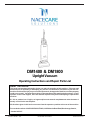
1
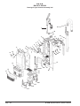
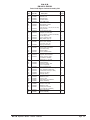
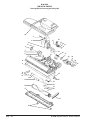
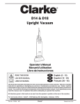
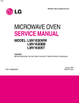
DM1400 & DM1800
Upright Vacuum
Operating Instructions and Repair Parts List
READ THIS BOOK
This book has important information for the use and safe operation of this machine. Failure to read
this book prior to operating or attempting any service or maintenance procedure to your N.A.C.E.
machine could result in injury to you or to other personnel; damage to the machine or to other property
could occur as well. You must have training in the operation of this machine before using it. If your
operator cannot read English, have this manual explained fully before attempting to operate this
machine.
Si Ud. no pueden leer el Inglés, se hagan explicar este manual completamente antes de tratar el
manejo o servicio de esta máquina.
All directions given in this book are as seen from the operator’s position at the rear of the machine.
For new books write to: NACECARE SOLUTIONS, 1205 Britannia Road East, Mississauga,Ontario,
Canada L4W iC7
Form No. 70720N
3/04
NACECARE SOLUTIONS
Printed in the U.S.A.
Table of Contents
Operator Safety Instructions ............................................................................................................. 3
Introduction & Machine Specifications ............................................................................................. 7
Grounding Instructions .................................................................................................................... 8
How To Assemble The Machine ....................................................................................................... 9
The Controls ..................................................................................................................................... 12
How To Operate The Machine .......................................................................................................... 14
Maintenance .................................................................................................................................... 15
How To Change The Filter Bag ............................................................................................ 15
How To Clean The Filter Cartridge ....................................................................................... 16
How To Replace The Brush ................................................................................................. 16
How To Change The Drive Belt ............................................................................................ 17
The Vacuum Indicator Light ................................................................................................. 17
The Circuit Breaker .............................................................................................................. 17
Brush Performance Indicator Lights .................................................................................................. 18
SECTION II Parts and Service Manual
Drawing #1 Upper Canister Assembly .............................................................................................. 20
Parts List #1 Upper Canister Assembly ............................................................................................ 21
Drawing #2 Brush Housing Assembly ............................................................................................... 22
Parts List #2 Brush Housing Assembly ............................................................................................ 23
Parts List #3 Hose Wand and Handle Assembly .............................................................................. 24
Page
-2-
N.A.C.E. Operator's Manual - DM1400 & DM1800
OPERATOR SAFETY INSTRUCTIONS
WARNING
AVERTISSEMENT
ADVERTENCIA
For the safe operation of this machine, read and understand all dangers, warnings and
cautions. Look for these symbols:
DANGER:
If you do not follow the instructions in a DANGER, severe bodily injury or death can occur to
the operator and/or other personnel.
WARNING:
If you do not follow the instructions in a WARNING, injury can occur to you or to other
personnel.
CAUTION:
If you do not follow the instructions in a CAUTION, damage can occur to the machine.
WARNING:
To reduce the risk of fire, electric shock, or injury:
1. You must have training in the operation of this machine before using it. READ THE
INSTRUCTION BOOK.
2. Do not use outdoors or on wet surfaces.
3. Do not leave vacuum cleaner unattended when plugged in. Turn off the switch and unplug the
electrical cord when not in use and before servicing.
4. Do not allow to be used as a toy. Close attention is necessary when used by or near
children.
5. Use only as described in this manual. Use only manufacturer's recommended attachments.
6. Do not use with damaged cord or plug. If vacuum cleaner is not working as it should, has
been dropped, damaged, left outdoors, or dropped into water, return it to a service center.
7. Do not pull or carry by cord, use cord as a handle, close a door on cord, or pull a cord around
sharp edges or corners. Do not run vacuum cleaner over cord. Keep cord away from heated
surfaces.
8. Connect to a properly grounded outlet only (refer to Grounding Instructions).
9. Do not use extension cords or outlets with inadequate current carrying capacity.
10. Turn off all controls before unplugging.
11. Do not unplug by pulling on cord. To unplug, grasp the plug, not the cord.
12. Do not handle plug or vacuum cleaner with wet hands.
13. Do not put any objects into openings. Do not use with any opening blocked, keep free of
dust, lint, hair, and anything that may reduce airflow.
14. This vacuum cleaner creates suction and contains a revolving brush. Keep hair, loose
clothing, fingers and all parts of body away from openings and moving parts.
15. Do not pick up anything that is burning or smoking, such as cigarettes, matches or hot
ashes.
N.A.C.E. Operator's Manual - DM1400 & DM1800
Page
-3-
WARNING:
To reduce the risk of fire, electric shock, or injury:
16. Belt pulleys can become hot during normal use. To prevent burns, avoid touching the belt
pulley when servicing the drive belt.
17. Do not use to pick up flammable or combustible liquids such as gasoline, or use in areas
where they may be present.
18. Unplug the machine before servicing the belt or brush. The brush may start suddenly and
cause injury.
SAVE THESE INSTRUCTIONS
Page
-4-
N.A.C.E. Operator's Manual - DM1400 & DM1800
CONSIGNES DE SÉCURITÈ DE L'UTILISATEUR
AVERTISSEMENT
Pour utiliser cet appareil en toute sécurité, il faut lire et coprendre tous les consignes de danger,
d'avertissement et d'attention. Soyez attentif aux symboles que voici.
DANGER:
Ne pas respecter les consignes d'un avis de DANGER, peut occasionner la mort ou des
lesions corporelles graves pour l'utilisateur et/ou d'autres pesonnes.
AVERTISSEMENT: Ne pas respecter les consignes d'un AVERTISSEMENT peut occasionner des lesions
corporelles pour l'utilisateur et/ou d'autres personnes.
ATTENTION:
Ne pas respecter les consignes d'un avis d'ATTENTION peut occasionner des dommage
à l'appareil.
AVERTISSEMENT:
Pour réduire le risque de feu, de choc électrique, ou de blessure:
1. Vous devez recevoir une formation appropriée avant de vous servir de cet appareil. LISEZ LE
MANUEL DE CONSIGNES DU FABRICANT.
2. Ne pas utiliser à l'extérieur ou sur des surfaces mouillées.
3. Ne laissez pas l'aspirateur seul quand il est branché. Fermez le commutateur et débranchez
l'appareil lorsque vous ne l'utilisez pas ou avant le nettoyage ou l'entretien.
4. Ne permettez pas que l'aspirateur soit utilisé comme un jouet. Une attention particulière est
nécessarie lorsqu'il est utilisé par ou près d'un enfant.
5. Suivez strictement les recommandations d'utilisation de ce manuel. Utilisez uniquement les
accessoires recommandés par le fabriquant.
6. N'utilisez jamais l'aspirateur si le cordon ou la fiche sont endommagés. Si l'aspirateur ne
foncitionne pas comme il le devrait, s'il a été échappé, s'il est endommagé, s'il a été laissé à
l'extérieur ou échappé dans l'eau, retournez-le à un centre de service avant de l'utiliser.
7. Ne tirez pas l'aspirateur ou le transportez par le cordon. N'utilisez pas le cordon en guise de
poignée. Ne fermez pas uen porte sur le cordon ou tirez le cordon sur des bordures ou des
coins pointus. Ne passez pas l'aspirateur sur le cordon. Tenez le cordon à distance des
surfaces chauffantes.
8. Branchez toujours l'aspirateur dans une prise à trois (mise à terre).
9. N'utilisez pas des rallonges ou des prises qui n'ont pas une capacité suffisante pour transporter le courant.
10. Mettez sur arrêt tous les boutons de commande avant de débrancher.
11. Ne débranchez pas l'aspirateur en tirant sur le cordon. Pour débrancher, tenez la fiche et
non pas le cordon.
12. Ne manipulez pas la fiche ou l'aspirateur avec les mains mouillées.
14. N'insérez rien dans les ouvertures. N'utilisez pas l'aspirateur si des ouvertures sont
bloquées. Assurez-vous qu'elles soient dégagées de poussière, de mousse, de cheveux ou
de tout autre chose qui pourrait réduire le passage de l'air.
15. Cet aspirateur crée de la succion et contient une rouleau-brosse tournant. Tenez les parties
mobiles et les ouvertures loin des cheveux, du linge, des doigts et de toute partie du corps.
N.A.C.E. Operator's Manual - DM1400 & DM1800
Page
-5-
AVERTISSEMENT:
Pour réduire le risque de feu, de choc électrique, ou de blessure:
16. Ne remassez pas de objets qui brûient ou fument comme les cigarettes, les allumettes ou
les cendres chaudes.
17. Les poulies de la courroie peuvent devenir chaudes pendant l'utilisation normale. Pour
prévenir des brûlures, évitez de toucher la poulie lors de l'entretien de la courroie.
18. Débrancher la machine avant de faire l'entretien de la courroie ou de brosse. La brosse
peut démarrer soudainement et causer des blessures.
CONSERVEZ CES INSTRUCTIONS
Page
-6-
N.A.C.E. Operator's Manual - DM1400 & DM1800
INTRODUCTION
The DM1400 & DM1800 are upright vacuums for cleaning carpet. These machines are used to remove dry material
from carpet. These machines are intended for commercial use.
MACHINE SPECIFICATIONS
Model
DM1400
DM1800
Power Supply
120V-60 Cycle
120V-60 Cycle
Vacuum Motor
Brush RPM
Cord
Wheels (2)
Wand
Hose
1050 Watts
4300 rpm
50 ft. 3-wire
2.7" x 1.25"
21" extends to 33.5"
1.5" x 18.5"
extends to 72"
Chevron Brush Pattern
14"
6 lt, 2-ply disposable
1050 Watts
4300 rpm
50 ft. 3-wire
2.7" x 1.25"
21" extends to 33.5"
1.5" x 18.5"
extends to 72"
Chevron Brush Pattern
18"
6 lt, 2-ply disposable
20 lbs.
26 lbs
10.5 x 14.25 x 46.5
One Year
20.5 lbs.
26.75 lbs
10.5 x 14.25 x 46.5
One Year
Agitator Brush
Cleaning Width
Filter Bags
Weight (less power
cord)
Shipping Weight
Vacuum Dimensions
Warranty
N.A.C.E. Operator's Manual - DM1400 & DM1800
Page
-7-
GROUNDING INSTRUCTIONS
Grounded
Outlet Box
Preparation:
The following are instructions for connection to the
power supply and the electrical ground.
This machine must be connected to the electrical ground to
protect the operator from electrical shock. The machine has
an approved power cord with three conductors and a plug
with three terminals. Connect the plug to a receptacle that
has three holes and is connected to the electrical ground.
The green (or green and yellow) conductor in the cord is the
ground wire. Never connect this wire to any terminal other
than the ground pin terminal.
DANGER:
Improper connection of
Grounding Blade
is longest of the
three blades
FIGURE A
the equipment-grounding conductor can result
in risk of electric shock. Check with a qualified
electrician or service person if you are in doubt
as to whether the outlet is properly grounded.
Do not modify the plug provided with the
appliance. If it will not fit the outlet, have a
proper outlet installed by a qualified
electrician.
This machine is for use on a 110 to 120 Volt AC 60 cycle
electric circuit. Make sure you have the correct frequency
and voltage before connecting the power cord to an outlet.
The machine has a plug as shown in figure A.
WARNING: Always use this machine with an AC
three-conductor electrical system connected to
the electrical ground. Replace any worn, cut or
damaged cords. Replace any damaged plugs,
receptacles or connector bodies.
WARNING: Do not cut, remove, or break the
ground terminal. Do not try to fit a three-terminal plug into a receptacle or connector body
that does not fit the plug, see your Authorized
N.A.C.E. Dealer to get an authorized person to
make the connection.
WARNING: Do not move the machine over an
electrical cord. Always lift the cord over the
machine.
EXTENSION CORDS:
Use only an approved extension cord with three conductors,
a plug with three terminals and a connector body with three
holes. This machine has a power cord with wire size 18
AWG (AWG means American Wire Gauge).
WARNING: If you use an extension cord, use an
extension cord with minimum wire size 16 AWG.
Do not use an extension cord longer than 50
feet. Do not join two extension cords.
Page
-8-
N.A.C.E. Operator's Manual - DM1400 & DM1800
INSTRUCTIONS VISANT LA MISE A LA TERRE
PREPARATION:
Consignes pour brancher l'appareil a la source d'energie
et pour la mise à la terre.
Boîte de Prise
de Terre
Cet appareil doit être mise à la terre afin d'eviter le risque de
choc électrique. Cet appareil est pourvu d'un cordon muni de
trois conducteurs et d'une fiche munie de trois bornes.
Brancher la fiche à une prise qui a trois tous et est mise à la
terre. Le conducteur vert (ou vert et jaune) dans le cordon
est le fil neutre. Ne jamais attacher ce conducteur à une
borne autre que la borne à terre.
DANGER:
Un conducteur de terre
mal raccordé peut entraîner un risque de choc
électrique. Consulter un electricien ou un
technicien qualifié si vous n'êtes pas certain
que la prise est correctement mise à la terre. Ne
pas modifier la fiche fournie avec l'appareil. Si
elle ne peut être insérée dans la prise, faire
installer une prise adéquate par un électricien
qualifié.
LA LAME DE
TERRE EST LA
PLUS LONGUE
DES TROIS
LAMES
FIGURE A
Note: Au Canada, l'utilisation d'un adaptateur
temporaire n'est pas autorisée par le Code
canadien de l'électricité.
Cet appareil est destiné à un circuit de 110 à 120 volts et 60
cycles. S'assurer que l'appareil est branché à une prise de
courant ayant la même configuration que la fiche. Cet
appareil est muni d'une fiche de mise à la terre semblable à
celle illustrée par la Figure A.
AVERTISSEMENT: Toujours employer cet
appareil avec un système électrique AC à trois
conducteurs, raccordé à la mise à la terre.
Remplacer tout cordon usé, coupé ou
endommagé. Remplacer toute fiche ou prise
endommagée.
AVERTISSEMENT: Ne pas couper, briser, ou
enlever la prise de terre. Ne pas chercher à
brancher la fiche à trois bornes, à une prise que
ne lul correspond pas. Si la prise ne correspond
pas à la fiche, contacter votre agent de vente
autorisé des appareils N.A.C.E. afin qu'une
personne qualifiée effectue le branchement.
AVERTISSEMENT: Ne pas faire passer l'appareil
sur le cordon électrique. Soulever toujours le
cordon pour faire passer l'appareil en dessous.
LES RALLONGES:
Utilise seulement une rallonge approuvée à trois fils
conducteurs, munie d'une fiche à trois bornes et d'une prise
à trois trous. Cet appareil est muni d'un cordon électrique
dont les fils sont de calibre 16 AWG (AWG signifie American
Wire Gauge).
AVERTISSEMENT: Si vous utilisez une rallonge,
celle-ci doit avoir un calibre de fil minimum de
16 AWG. Ne pas utiliser de rallonge qui dépasse
50 pieds (15 mètres) de long. Ne pas raccorder
deux rallonges ensemble.
N.A.C.E. Operator's Manual - DM1400 & DM1800
Page
-9-
HOW TO ASSEMBLE THE MACHINE
To assemble the machine, follow this procedure:
1. Remove the brush housing, vacuum bags, hose,
wand, handle assembly, canister housing, and
tools from the carton.
2. Remove the canister housing and the brush
housing from the plastic bags.
3. Install the canister housing on the brush housing.
To install the canister housing, follow this procedure:
a.
Position canister housing over brush housing
(see figure 2).
b.
Align pivot airway (A) and canister support
pivot (B) with openings (C and D) in bottom of
canister housing (see figure 2).
c.
Lower canister housing completely onto brush
housing until pin clicks into place and latches
(see figure 3).
C
A
D
B
Figure 2
4. Install the handle assembly to the canister housing. To install the handle assembly, follow this
procedure:
a.
Insert handle tube in the upper canister
housing (see figure 4).
b.
Lower handle completely into canister housing
until mark on handle tube is below flush (see
figure 5, item A). This insures the handle is
properly seated.
c.
Figure 3
Push handle latch into lock position (see
figure 5, item B).
A
Mark on
handle tube.
B
Figure 5
Page
-10-
Figure 4
N.A.C.E. Operator's Manual - DM1400 & DM1800
5. Install the wand assembly in the right rear canister
housing (see figure 6, item A).
6. Position wand handle so that handle is towards
the front of the machine (see figure 7, item A).
7. Attach hose to wand and canister (see figure 7).
To attach hose properly, depress lock on canister
(see figure 7, item B).
8. Snap the crevice (B) and upholstery (C) tools into
the tool retainer on rear of canister housing (see
figure 6).
A
C
B
Figure 6
B
A
B
Figure 7
N.A.C.E. Operator's Manual - DM1400 & DM1800
Page
-11-
THE CONTROLS
The Handle Release Pedal (See figure 8, item A)
The handle release pedal is on the lower left side of the
machine. Press the pedal to release the handle and start
the brush motor. The brush motor will not run unless the
ON/OFF switch is in the "I" position.
C
The ON/OFF Switch (See figure 9)
The ON/OFF switch is on handle. Put the switch in the
"I" position to start the vacuum motor. Put the switch in
the "O" position to stop the vacuum motor. Putting the
switch in the off position will also shut off the brush
motor.
B
A
The Height Adjustment (See figure 8, item B)
The height adjustment is located on the lower right side
of the machine. Press the front of the pedal with your
foot when vacuuming shorter carpet. Press the back of
the pedal with your foot when vacuuming thicker, longer
carpet.
Figure 8
The Wand (See figure 8, item C)
The wand is in the holder in the back of the canister
housing. The wand has a telescoping feature (see figure
11). The crevice tool and the upholstery tools fit the end
of the wand. The wand has a suction control sleeve (see
figure 10). For normal vacuuming keep suction control
sleeve closed. To reduce suction, when cleaning drapes
or furniture, open suction control sleeve.
Figure 9
Figure 11
Page
-12-
Figure 10
N.A.C.E. Operator's Manual - DM1400 & DM1800
Canister Door (See figure 12, item A)
The canister door release is in the upper part of the
canister housing. Lift to open door.
NOTE: Door will not close without a properly mounted
filter bag. See page 11 for filter bag mounting instructions.
The Vacuum Indicator Light (See figure 12, item B)
The vacuum indicator light is on the top of the canister
housing. The indicator light comes on when the airflow to
the vacuum motor is obstructed.
B
NOTE: See page 17 for instructions on how to remove an
obstruction.
A
The Cord Storage Hooks (See figure 13)
The cord storage hooks are on the back of the canister
housing. The lower cord hook is also a carrying handle.
The lower cord hook rotates to provide a quick cord
release and to ease cord removal.
Figure 12
Figure 13
N.A.C.E. Operator's Manual - DM1400 & DM1800
Page
-13-
HOW TO OPERATE THE MACHINE
CAUTION: To prevent damage to the machine,
do not allow large objects to be pulled into the
lower housing or the attachments.
NOTE: The machine comes with a filter bag installed
in the canister housing.
Use the DM1400 & DM1800 as a carpet cleaner or as an
upholstery cleaner. To operate the machine as a carpet
cleaner, follow this procedure:
1. Remove the power cord from the cord storage
hooks, by rotating the lower cord hook 180° (see
figure 14).
2. Connect the electrical plug to the electrical
outlet.
3. Put the ON/OFF switch in the "I" position (see
figure 9).
Figure 14
4. Press the handle release pedal (see figure 8,
item A).
5. Pull the handle toward you to the best operating
position.
6. Move the machine forward and backward over the
carpet.
To operate the machine as an upholstery cleaner, follow
this procedure.
1. Make sure the ON/OFF switch is in the "O"
position.
2. Push the handle forward until it locks in position.
NOTE: the machine comes with a crevice tool
attachment and an upholstery tool attachment.
Select the tool needed for the cleaning operation.
Figure 15
3. Remove the wand from the canister housing.
4. Connect an accessory tool to the end of the
wand, or directly to the hose (see figures 15 and
16).
NOTE: Push button on wand handle to release
the hose from the wand (see figure 16, item A).
5. Put the ON/OFF switch in the "I" position.
A
6. Move the tool over the area to be cleaned.
Figure 16
Page
-14-
N.A.C.E. Operator's Manual - DM1400 & DM1800
MAINTENANCE
WARNING: To prevent injury, always remove
the electrical plug from the electrical outlet
before doing any maintenance or repairs to
the machine.
WARNING: Maintenance and repairs must be
done by authorized personnel only. Use only
genuine N.A.C.E. parts.
How To Change The Filter Bag
The machine uses a disposable paper filter bag. To change
the paper filter bag, follow this procedure:
1. Make sure the ON/OFF switch in the "O"
position and that the machine is disconnected
from the power supply.
2. Open the front of the canister housing. To open
the canister housing, lift the release handle (see
figure 17).
Figure 17
3. Grasp cardboard inlet on both sides of the bag
(see points A and B on figure 19) and slightly
rotate and pull bag out.
5. Install a new filter bag. To install a new filter bag,
follow this procedure:
a. Unfold the filter bag.
B
A
b. Hold the bag by the cardboard inlet.
c. Place the bottom of the cardboard inlet into
the slot under the bag adaptor (see figure 18,
item A)
d. Put the opening of the cardboard inlet over the
bag adapter (see figure 18, item B).
Figure 18
e. Make sure the cardboard is pushed all the way
on the bag adapter (figure 19) or the door will
not latch.
f. Close the canister housing.
A
B
Figure 19
N.A.C.E. Operator's Manual - DM1400 & DM1800
Page
-15-
How To Change The Filter Cartridge
Change the filter cartridge whenever it is dirty or suction
performance decreases. To change the filter cartridge,
follow this procedure:
1. Make sure the ON/OFF switch is in the "O"
position and the machine is disconnected from
the power supply.
2. Open the canister door.
3. Remove the filter bag.
4. Remove the filter cartridge (see figure 20).
5. Replace filter cartridge and filter bag (see figure
21).
CAUTION: Check the filter cartridge while
changing the paper bag. Replace the filter
cartridge when dirty or when the vacuum
suction performance drops off even with a
clean filter bag.
Figure 20
How To Replace The Brush
WARNING: To prevent injury, unplug machine
before cleaning or replacing brush. Brush
may start suddenly and cause injury.
1. Put the machine on its side.
2. Turn the knobs which secure the nozzle plate.
See figure 22.
3. Lift the nozzle plate up to remove it.
4. Lift the brush assembly up to remove it.
5. Install the new brush assembly.
Figure 21
6. Install the nozzle plate.
7. Put the machine on its wheels.
WARNING: To reduce the risk of injury from
moving parts, unplug before servicing.
Figure 22
Page
-16-
N.A.C.E. Operator's Manual - DM1400 & DM1800
How To Change the Drive Belt
WARNING: To prevent injury, unplug machine
before cleaning or replacing brush. Brush
may start suddenly and cause injury.
To change the drive belt, follow this procedure:
1. Put the machine on its side.
2. Lift the nozzle plate up to remove it.
3. Lift the brush assembly up to remove it (see
figure 23).
4. Remove the drive belt from the brush pulley.
5. Remove the drive belt from the motor shaft.
Figure 23
6. Put one end of the new drive belt around the
motor shaft.
7. Put the other end of the drive belt around the
brush pulley.
8. Install the brush assembly in the brush housing.
9. Install the nozzle plate.
10. Put the machine on its wheels.
WARNING: To reduce the risk of injury from
moving parts, unplug before servicing.
The Vacuum Indicator Light
If the vacuum indicator light (1) comes on, (see figure
24) or the motor stops, do the following:
1. Put the ON/OFF switch in the "O" position (2).
2. Remove the electrical plug from the electrical
outlet.
3. Check the vacuum hose for an obstruction. If
there is an obstruction in the vacuum hose,
remove the obstruction.
4. Check the brush assembly in the lower housing.
If there is an obstruction in the brush assembly,
remove the obstruction.
Figure 24
5. Check the filter bag. If the filter bag is over 1/2
full, change or empty the bag.
6. Check the filter cartridge. If the filter is dirty,
change the filter.
Thermal Overload
A thermal overload is used to protect the vacuum motor.
If the motor over heats, the thermal overload will stop
the motor. If the motor stops, let the motor cool before
restarting the machine. Check filters. If the motor
continues to stop, consult an authorized service person.
N.A.C.E. Operator's Manual - DM1400 & DM1800
Page
-17-
BRUSH PERFORMANCE INDICATOR LIGHTS
The UTV14 & UTV18 upright vacuums have 3 brush
performance indicator lights (see figure 25). They are
GREEN, YELLOW and RED. They work in the following
manner:
Normal Operation:
• The GREEN light is on when the brush drive motor is
on and the brush height setting is correct for the
carpet.
NOTE: It is normal for the red or yellow light to intermittently turn on and off as high or low surfaces are
encountered.
Brush Height Too High:
• The YELLOW light will continue to stay on when the
brush height is too high for the carpet. Lower the
brush height setting.
Figure 25
Brush Height Too Low or Brush Has Jammed:
• The RED light will continue to stay on when the brush
height setting is too low for the carpet. Raise the
brush height setting. The RED light will come on if the
brush is jammed.
• If the RED light is on continuously for 10 seconds, the
electronic safety stop will protect the brush motor by
turning it off.
• To reset the brush drive motor, put the operating
handle in the upright position. Turn the ON/OFF
switch to the off position. Restart the machine.
• If the brush height was too low, raise the brush height
setting.
• If the brush was jammed, unplug the vacuum and clear
the brush.
Page
-18-
N.A.C.E. Operator's Manual - DM1400 & DM1800
DM1400 & DM1800
Upright Vacuum
Repair Parts List
N.A.C.E. Operator's Manual - DM1400 & DM1800
Page
-19-
N.A.C.E.
DM1400 & DM1800
Drawing #1 Upper Canister Assembly 3/04
40
1
39
38
34
37
36 35 33
2
3
32
4
6
8
11
10
5
7
5
9
12
13
29
31
30
28
27
14
23
15
22
21
16
24
25
26
20
19
18
17
Page
-20-
N.A.C.E. Operator's Manual - DM1400 & DM1800
N.A.C.E.
DM1400 & DM1800
Parts List #1 Upper Canister Assembly 3/04
Ref.
No.
Part No.
1
1A
1B
1C
1D
1E
1F
2
53296A
53199N
53207N
53320A
53315A
53318A
53233A
53211N
3
4
5
6
53234A
53257A
53347A
53213A
7
8
9
10
11
53258A
53212A
53430A
53273A
53218N
12
13
14
53330A
53219N
53215N
15
16
17
18
19
53302A
53217N
53266A
53271A
53324A
20
21
22
23
53270A
53300A
53256A
24
25
26
27
28
29
30
31
32
33
34
35
36
37
38
53306A
53214A
53274A
53319A
53328A
53240A
53264A
53252A
53220N
53221N
53262N
53253A
53254N
53255A
53290N
39
40
53253A
53225N
Description
Handle Tube
Handle, Left
Handle, Right
On/Off Switch
Pad, Soft Touch
Power Cord
Receptacle, Handle
Canister, Rear
(incl. #4, 5, 6, 7, 28, 29, 30, 35, 36)
Plug, Canister
Pivot, Filter Bag Asm.
Screw, M4 x 16
Adaptor, Air Inlet Asm.
(incl. gaskets - 53307A & 53308A)
Guide, Bag Collar
Cover, w/Door Latch
Bag, Paper (pkg. 10)
Gasket, Door
Door, Asm. Canister
(incl. #10, 12 & 13)
Spring, Door Catch
Latch, Canister Door
Cover, Asm. Vac Motor
(incl. # 25 & 26)
Exhaust Filter
Cover, Exhaust Filter
Cover, 2 pc. Vac Motor
Spacer, Vacuum Motor
Motor, Vacuum 120V
(includes # 53356A)
Same as 17 - 2pc. Set
Endcap, Vac Motor
Filter Cartridge
Channel, Airway Asm.
(incl. receptacle)
Sound Insulation Set
Latch, Canister to Brush Hsg.
Pin, Canister to Brush Hsg.
Interconnect Cord (incl. #43)
Spring, Air Valve
Plunger, Spring
Retainer, Air Valve
Retainer, Tools
Crevice Tool
Upholstery Tool w/Brush
Wand Assembly
Handle, Cord Hook
Swivel, Cord Hook
Retainer, Hose
Clamp, Asm. Handle
(incl. 53210A & 53273A)
Bag Full Indicator
Hose Assembly
N.A.C.E. Operator's Manual - DM1400 & DM1800
No.
Req’d.
1
1
1
1
1
1
1
1
1
1
24
1
1
1
1
1
1
2
1
1
1
1
1
1
1
1
1
1
1
1
1
1
1
1
1
1
1
1
1
1
1
1
2
1
1
1
Page
-21-
N.A.C.E.
DM1400 & DM1800
Drawing #2 Brush Housing Assembly 3/04
1
2
13
3
36
4
35
5
34
13
6
7
8
9
33
32
31
37
30
8
10
29
28
27
26
11
12
13
14
25
14
15
24
23
22
16
21
20
17
19
18
Page
-22-
N.A.C.E. Operator's Manual - DM1400 & DM1800
N.A.C.E.
DM1400 & DM1800
Parts List #2 Brush Housing Assembly 3/04
Ref.
No.
1
2
3
4
5
6
7
8
9
10
11
12
13
14
15
16
17
18
19
20
21
22
23
Part No.
53231N
53232N
53245A
53243A
53259N
53219A
53248A
53227N
53228N
53267A
53268A
53331A
53355A
53284A
53229A
53260A
53261A
53250N
53251N
53263A
53354A
53350A
53286A
53282A
53230A
24
25
26
27
28
29
30
53325A
31
32
33
34
35
36
53249A
53326A
53275A
53333A
53241A
37
53293A
53348A
53285A
Description
Qty.
Cover Asm., Brush Hsg. 14"
1
Cover Asm., Brush Hsg. 18"
1
(cover asm. include #2)
Pedal, Brush Height
1
Pivot Asm., Airway
1
(incl. 53236A; 53244A Bracket,
Airway Right; & 53243A Bracket,
Airway Left)
Cotter Pin
2
Hub Cap
2
Axle Hub
2
Spacer, Rear Wheel
4
Rear Wheel
2
Brush Housing Asm. 14"
1
Brush Housing Asm. 18"
1
(incl. 53312A, 53313A, 53263A (18))
Bumper 14"
1
Bumper 18"
1
Spring, Brush Height Shaft
1
E-clips M6
4
Guide, Brush Height Shaft
1
Rollers
3
Brush Assembly 14"
1
Brush Assembly 18"
1
Bottom Plate 14"
1
Bottom Plate 18"
1
Tension Lever
2
Belt
1
Screw, Flathead M4 x 15
2
Retainer, Door and Rollers
1
Shaft, Rollers
1
Cleanout Door Asm.
1
(incl. 53311A, 53278A & 53322A)
Screw, M5 - .8 x 24
2
Washer, M5
2
Screw, M4 - .7 x 10
2
Washer, M4
2
Bracket, Brush Motor
1
Nuts, M5 - .8
2
Motor, Brush 120V
1
(incl. #26, 27, 28, 31 & 53298A)
Endcap, Brush Motor
1
Pedal, Foot Latch
1
Circuit Board 120V
1
Pin, Support Pivot
1
Spring (include with #36)
1
Support Asm., Canister Pivot
1
(includes #13, 34, 35)
Rear Axle (includes #7)
1
N.A.C.E. Operator's Manual - DM1400 & DM1800
Page
-23-
N.A.C.E.
DM1400 & DM1800
Electrical Schematic 3/04
Page
-24-
N.A.C.E. Operator's Manual - DM1400 & DM1800
NOTES
N.A.C.E. Operator's Manual - DM1400 & DM1800
Page
-25-
NACECARE SOLUTIONS
U.S. LIMITED WARRANTY
This N.A.C.E. Industrial/Commercial Product is warranted to be free from defects in materials and workmanship under
normal use and service for a period of one year from the date of purchase, when operated and maintained in accordance
with N.A.C.E. Maintenance and Operations instructions.
This brush drive and traverse motors are warranted to be free from defects in materials and workmanship under normal
use and service for one year from the date of purchase, provided the motors are inspected for carbon motor brush wear
at six-month intervals by an authorized N.A.C.E. service center. Failure to comply with the six-month inspection requirement
or failure to replace worn motor brushes identified during the inspection will void the one-year warranty on the motors. Cost
of the six-month inspection and replacement of carbon motor brushes is the responsibility of the purchaser. In the event of
a warranty claim on the motors, proof of inspection and any required motor brush replacement must be provided.
This warranty is extended only to the original purchaser for use of the product. It does not cover normal wear parts such
as electrical cable, rubber parts, and motor brushes.
N.A.C.E.'s liability under this warranty is limited to repair of the product and/or replacement of parts and is given to
purchaser in lieu of all other remedies, including INCIDENTAL AND CONSEQUENTIAL DAMAGES.
THERE ARE NO EXPRESS WARRANTIES OTHER THAN THOSE SPECIFIED HEREIN. THERE ARE NO WARRANTIES WHICH
EXTEND BEYOND THE DESCRIPTION OF THE FACE HEREOF. NO WARRANTIES, INCLUDING BUT NOT LIMITED TO WARRANTY OF MERCHANTABILITY, SHALL BE IMPLIED.
If a difficulty develops with the product, you should: a) Contact the nearest authorized N.A.C.E. service center or contact
N.A.C.E., 1205 Britannia Road East Mississauga, Ontario, Canada for the nearest authorized N.A.C.E. service center. Only
these locations are authorized to make repairs to the product under this warranty. (b) Return the product to the nearest
N.A.C.E. Service Center. Transportation charges to and from the repair location must be prepaid by the purchaser. N.A.C.E.
will repair the product and/or replace any defective parts with out charge within a reasonable time after receipt of the
product.
NACECARE SOLUTIONS
reserves the right to make changes or
improvements to its
machine without notice.
1205 Britannia Road East
Mississauga, Ontario,
Canada L4W IC7
Tel: 905 795 0122 Toll Free: 1 800 387 3210
Fax: 1 800 709 2896