1
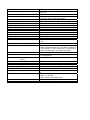
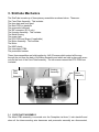
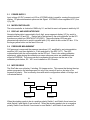
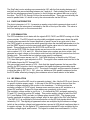
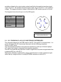
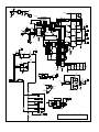
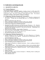
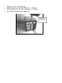
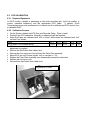
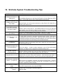
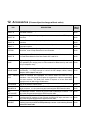
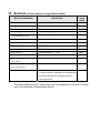
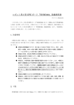
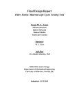
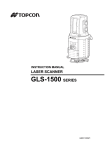
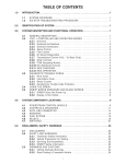
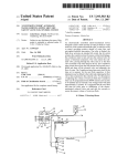
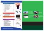
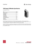
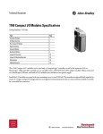
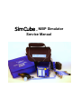
SimCube
NIBP Simulator
Service Manual
TM
In terms of the requirement of European Council Directive 2002/95/EC of
27 January 2003 (RoHS), SimCube NIBP Simulator Models SC-1, SC-2,
SC-3, SC-4, SC-5, SimCube Battery Boost Option, power supplies and
accessories are excluded in accordance with Article 2, Paragraph 1 as
these products fall into Category 9, Annex 1A set out in Directive
2002/96/EC of 27 January 2003 (WEEE).
To dispose this product, contact Pronk Technologies at
[email protected]. We will issue a RMA and pay for return
shipment.
SimCube, Pronk, and Pronk Technologies are trademarks of Pronk Technologies Inc.
©2007 Pronk Technologies Inc. All rights reserved.
Table of Contents
Contact Us
Sales:
Technical Support:
FAX:
Email:
Web site:
800-609-9802
800-541-9802 or 818-768-5604
818-768-5606
[email protected] for sales
[email protected] for service
www.pronktech.com
SimCube Service Manual
TM
Models SC-1, SC-2, SC-3, SC-4 and SC-5
1. Overview
1.1 SIMCUBE OVERVIEW
The SimCube simulation system provides NIBP simulation in a small, portable, easy to use
package. In addition to NIBP simulation, optional ECG, respiration and invasive blood
pressure simulation are available. Combined with the Battery Boost option and the OxSim
the SimCube family or products are the biomedical engineer’s ultraportable tools of choice.
1.2 CALIBRATION OVERVIEW
Calibration of the SimCube is simple and may be done by qualified individuals by using the
processes provided in this document. NIBP calibration is done via an access hole on the
top of the SimCube. ECG R-wave calibration is done by lifting the faceplate and accessing
the calibration potentiometer located on the ECG PCBA. IBP is calibrated at the factory with
0.1% resistors. If IBP calibration check yields the need for re-calibration, contact Pronk
Technologies technical support for assistance.
1.3 WARRANTY
The SimCube has a three year warranty. Pronk Technologies provides many assembly
level parts to repair the SimCube if it is out of warranty or if it is necessary to performs
repairs outside of the factory. A list of parts is provided in this document.
1.4 SERVICE CAUTION
The SimCube is small, and so all the electronics, mechanics and pneumatics that make up
the SimCube are compact and specifically routed. When opening up the SimCube care
must be taken to note the routing and positioning of all harnesses, pneumatics and other
assemblies. When reassembling these must be correctly re-positioned to ensure proper
operation of the SimCube. If you have any questions, please feel free to contact us.
1.5 TECHNICAL SUPPORT
Pronk Technologies is dedicated to providing support to our customers in whatever manner
they need. Our technical support staff are available by phone or email to provide help from
operation level to component level. Whether it is an application issue, a service issue, or
your thoughts about how our products could better fit your needs, we look forward to
hearing from you.
2. SimCube Specifications
Physical Dimensions
Size
Weight
Power
NIBP Connection
ECG/Resp Connection
IBP Connection
Manometer
Range
Precision
Accuracy
User Interface
Single Button Operation
Operating Modes
NIBP Adult Simulation
Simulated Pressure
Simulated Heart Rate
Simulated Pulse Volume
NIBP Neonatal Simulation
Simulated Pressure
Simulated Heart Rate
Simulated Pulse Volume
NIBP Hypertensive Simulation
Simulated Pressure
Simulated Heart Rate
Simulated Pulse Volume
NIBP Hypotensive Simulation (SC-5)
Simulated Pressure
Simulated Heart Rate
Simulated Pulse Volume
ECG Simulation (SC-2, 4, 5)
Isolated
Synchronized with NIBP
R Wave Size
R Wave Width
Wave Shape
3”x 3” x 3.5” (7.6cm X 7.6cm X 8.9cm)
2.5 Lbs
External A/C Adaptor
(Output: 6VDC / 2amps,
2.1mm, center positive connector) or
4 AA Batteries (with Battery Boost Option)
Quick Disconnect, Female
10 ECG snaps
Mini-DIN
(SC-1, 2, 3, 4) 0 – 480 mmHg
(SC-5) – 400 to + 400 mmHg
(SC-1, 2, 3, 4) 0.5 mmHg
(SC-5) 0.1 mmHg
+/-1% of reading
Adult NIBP
Neo NIBP
Hypertensive NIBP
Hypotensive NIBP (SC-5 only)
Manometer
Peak Detect (SC-3, 4, 5 only)
HR Seq. Alarm Test (SC-4, 5 only)
ECG Pace ON
Arrhythmia Sequence (SC-5 only)
Heart Rate Sequence (SC-4, 5 only)
Invasive BP Zero (SC-5 only)
Invasive BP 100, 200 (SC-5 only)
Invasive BP Sequence (SC-5 only)
120/80 (100) mmHg
70 bpm
1 ml
70/40 (55) mmHg
95 bpm
0.5 ml
190/120 (150) mmHg
70 bpm
1 ml
80/40 (60) mmHg
70 bpm
1 ml
Yes
Yes
1mV (lead I) +/- 5%
35 ms
QRS wave
Connection
Simulation Rates
10 Snaps
70, 95, Asystole, Arrhythmia (SC-5), Pacer, HR seq.
(SC-4, 5)
HR Sequence (SC4, 5)
30 seconds each of:
30, 60, 90, 120, 45, 160, and 220 bpm
Pacer Simulation
Isolated
Synchronized with NIBP
Pacer Size
Pacer Width
Respiration Simulation
Isolated
Synchronized with NIBP
Wave Shape
Size
Rate
Simulation rates
Yes
Yes
3 mV
1.2 ms
Yes
Yes
Square Wave
4 Ohm
35 bpm (47 bpm for neonatal)
20, 40, Apnea, Sequence = 00, 30, 45, 60, 22, 30, 80,
110.
Arrhythmia Simulation (SC-5)
Cardiac failure sequence: ~ 90 seconds of normal
beats interspersed with PVCs and Runs, followed by
~20 seconds of VTAC, followed by ~35 seconds of
VFIB, concluding with ~30 seconds of asystole.
Peak Detect
Precision
Invasive Blood Pressure Simulation
(SC-5 )
Isolated
Synchronized with NIBP
Excitation Voltage
Pressure range
Simulated Pressure accuracy
Wiring
Simulation rates
Environmental
Voltage Range
0.5mmHg (SC-4)
0.1mmHg (SC-5)
Yes
Yes
DC range = 3.3 to 5.7 AC range = 6.65 to 11.4p-p
0-250 mmHg
+/- 1 mmHg
+ Excit = pin 1, - Excit = pin 4, + Sig = pin 3, -Sig = pin
6
Dynamic = 120/80, 70/40, 190/120.
Static = 0, 100, 200.
Step = 0,25,50,100,150,200, 250
100-240 VAC, 50-60 Hz
3. SimCube Mechanics
The SimCube is made up of three primary assemblies as shown below. These are:
The Face Plate Assembly. This includes:
The face plate and front decal
The Main PCB on standoffs
The pneumatic bulkhead
The IBP connector (SC-5 only)
The Housing Assembly. This includes:
The Metal housing
The power Jack
The ECG PCB and Snaps (if applicable)
The Motor Assembly. This includes:
The Motor
The NIBP plastic
The Interrupter PCBA
The pneumatic harness
These three assemblies are held together by 4 #6-32 screws which extend all the way
through the unit from the back of the Motor Assembly and which are held in place with acorn
nuts on the front of the Face Plate Assembly. The two screws nearest the ECG PCBA are
insulated.
Face
Plate
Assembly
Housing
Assembly
Motor
Assembly
3.1 FACE PLATE ASSEMBLY
The Main PCBA assembly is mounted onto the Faceplate via three ¼ inch standoffs and
when all the interconnecting wire harnesses and pneumatic assembly are disconnected,
can be removed from the SimCube as a complete assembly. With the Face Plate Assembly
removed from the unit, the main PCBA can be removed by removing the three plastic nuts
holding it in place. There are two different main PCBA assemblies. The SC-1 through SC-4
Main PCBA is based on a PIC16F872, while the SC-5 SimCube is based on a PIC16F876.
A SC-5 Face Plate assembly is shown below. The layout of a SC-4 through SC-4
Face Plate assembly is the same except that that there is no IBP connector and the
programming connector is populated differently. Also, the SC-1 through SC-4 use analog
rather than digital calibration, so the Calibration switch is replaced with a calibration
potentiometer.
SC-5 Face Plate Assembly
Program / Comm
Connector
(8 pin)
CPU
Pressure
Transducer
Interruptor
Connector
(3 pin)
ECG
Connector
(4 pin)
Pneumatic
Bulkhead
IBP
Connector
(6 pin)
Calibration
Button
Motor
Connector
(4 pin)
IBP
Mini-Din
Connector
3.2 HOUSING ASSEMBLY
The housing assembly is shown below.
ECG
Snaps
Calibration
Hole
Power
Jack and
Harness
ECG
PCBA and
Harness
The ECG PCBA is mounted on the shafts of the snaps on the inside of the Housing
Assembly. Note that for proper operation the ECG it must be electrically isolated from the
rest of the assembly. Opto-couplers carry the signals across while keeping the ECG circutry
isolated, but it is also critical to maintain the mechanical isolation between the PCBA and
the aluminum housing. The correct stack up of mounting hardware to maintain this
isolation is shown below. The snap feeds from the outside of the housing through a plastic
shoulder washer. On the inside of the housing a plastic washer sits between the housing
and the PCBA. On the top of the PCBA the snap is retained and held to the pad on the
PCBA via a lock-washer and a #4-40 small pattern nut. Metallic contamination under the
ECG PCBA on any of the plastic hardware can violate the electrical isolation and lead to
reduced ECG performance.
ECG
Snap
Shoulder
Washer
Plastic
Washer
Lock
Washer
and Nut
A calibration hole is provided in the top of the housing assembly to allow calibration of the
manometer without disassembly of the unit. It can be accessed by lifting the foil tape.
On the wiring harness that comes from the ECG PCBA, Pin 1 or Red color wire is ECG,
which contains the digitized ECG signal, Pin 3 or Blue color wire is RESP, which contains
the digitized respiration, and Pin 2 or Green color wire is PACE, which contains the pacer
artifact signal. Pin 4 or the black wire is ground.
3.3 MOTOR ASSEMBLY
The Motor Assembly is shown below:
Motor
Pneumatic
Harness
Cam
Slide
Bearing
Elastic
Tube
Interrupter
PCBA
Home
Position
Dot
Frame
This assembly functions as follows: The Motor turns the Cam, which moves the Slide (via
the bearing) and compresses the Elastic Tube, which creates pressure pulses. The
pressure pulses are conveyed to the bulkhead and pressure transducer via the pneumatic
harness. A tab on the top of the Slide breaks the beam of a photo interrupter, which is
mounted on the interrupter PCBA. The Frame provides the structure for the assembly.
The Cam is equipped with a home position Dot, which allows us to observe and express
Cam position and movement. Cam position is expressed in terms of clock hands with the
assembly oriented as shown. Normal home position (shown), for example, is usually
between 12:30 and 1:30.
Note that all connections on the pneumatic harness are sealed with silicone glue to reduce
any chance of leakage around the hose barbs on the fittings. If the harness is
disassembled for any reason all joints that have been disturbed should re-glued.
4. SimCube Electronics
VCCRAW
U8
lp2951
8 IN
OUT1
7 FBKSENS2
6 TAPSHDN 3
5 ERR GND 4
VCC
R24
2k
C6
1000uF
C7
47uF
TP2
TP
R25
1k
R10
R5
10k
R4
1k
R1
10k
VCC
R26
1k
R7
10k
16 VCC
14
11 DATA
CLK
12 LD
13
10 /OE
9 /CLR
8 OUT
GND
MCLR
B7
A0
B6
A1
B5
A2
B4
A3
B3
A4
B2
A5
B1
GND
B0
CLKIN
VCC
CLKOUT
GND
C0
C7/RXS
C1
C6/TXS
C2
C5/SDO
C3/SCK
C4/SDI
PCUFF
HOME
10MHZ
C2
22pf
C1
22pf
PACE
ECG
SCLOCK
2
VCC
S2
C18
47uF
U1
74HC595
U6
PIC16F873A
VR1
100K 50%
O0 15
O1 1
O2 2
O3 3
O4 4
O5 5
O6 6
O7 7
VCC
C19
0.1u
VCCRAW
R14
IRF7304
500
Q1A
R15
IRF7304
Q2B
Q2A
TP6
TP
Q1B
TP7
TP
IBPLD
MODEEN
MODELD
MOTORLD DIGLD
VCC
VCC
500
R2
1K
RXSERIAL
TXSERIAL
SDATAOUT
SDATAIN
2
S1
J30
GND
1
IRF7307
R16
1
R3
1k
R13
500
R23
10K
J5
R12
500
500
R8
10k
MOTOROE
VCC
R11
500
VCCRAW
+
+
J32
+
5.
IRF7307
500
C5
0.1u
Q3B
TP8
TP
Q4B
VCCRAW
P Channel
J6
RESP
U7
Q5
NPN
Q6
NPN
R46
1k
VCC
DATA
CLK
LD
/OE
/CLR
OUT
GND
R32
500k
R18
100k 40%
VCC
DATA
CLK
LD
/OE
/CLR
OUT
GND
DIGLD
ISOGND
C14
0.1u
D4
LED0
D5
LED0
D6
LED0
D7
LED0
1 2
D3
LED0
1 2
D2
LED0
1 2
VCCRAW
R33
200k
O0 15
O1 1
O2 2
O3 3
O4 4
O5 5
O6 6
O7 7
1 2
16 VCC
14 DATA
11
12 CLK
13 LD
10 /OE
9 /CLR
8 OUT
GND
SDATAOUT
SCLOCK
MODELD
MODEEN
Q10
NPN
U14
1 TLP190
OUT+ 6
3 IN+
IN- OUT-4
O0
O1
O2
O3
O4
O5
O6
O7
U10
74HC595
R34
500k
Q9
PNP
TP22
TP
C11
0.1u
U9
74HC595
1 2
C13
0.1u
VCCRAW
1 2
OUT-4
O0
O1
O2
O3
O4
O5
O6
O7
R19
1K
1 2
3 IN-
R30
100k
Q4A
Q3A
U2
74HC595
Q8
NPN
TP21
TP
U15
TLP190 6
1 IN+
OUT+
500
Q7
NPN
TP20
TP
TP9
TP
N Channel
R17
DIG1
B
DIG2
G
D
A
L
C
E
NC
DIG3
F
DP
NC
DIG4 NC
D8
LED0
C12
0.1u
ISOGND
R50
620
ISOGND
J8
H21A1
U12
1 LEDA
2 LEDC
TP4
TP
R51
10K
TP3
TP
VCC
J7 J4
E4
C3
HOME
VCC
U13
TLP190 6
1 IN+
OUT+
U4
OUT-4
R52
100k
C26
0.1u
R44
200k
ISOGND
R9
100k
C25
1u
R55
1M
R36
60k
J17
914
C17
47uF
C8
1u
C10
1u
C9
1u
C15
1u
C1+
VCC
V+
GND
C1- ROUTA
C2+
RINC
C2- TOUTC
VTINA
ROUTB TINB
RIND TOUTD
Q11
PMBFJ109
D
S
V3
P1
R39
360
C3
0.1u
DIGLD
SDATAIN
SCLOCK
U18
12F508
P1
U19
1 IRDET
VCC GND
B5 B0/PD
B4 B1/PC
B3/VP B2
LL
2 VOUT
3 GND
VCC
P1
LA
VCC
V2
SDATAOUT
SCLOCK
IBPLD
P1
R49
4.3k
R43
60k
R48
4.3k
RL
VCC1
VCC2
GND1
GND2
IN1 OUT2
IN2 OUT2
IN3 OUT3
IN4 OUT4
NC
NC
GND1
GND2
C16
47uF
5
C23
10pf
7
U30A
+2
C22
1u
R56
30
OUT CF+
IN
CFM GND
C24
R58
1.02k
0.1%
R45
1.02k
0.1%
U20
TPS60403
1u
P1
1
ISOGND
U30B
MCP6002
6 +
CLK *CS
SDI VDD
RFB GND
VREFIOUT
C27
100uF
+
P1
U11
DAC8811
8
P1
U16
HCPL-090J
C20
1u
4
R42
499
RA
R35
30k
0.1%
R53
30k
0.1%
J2
EXPLUS
BP2PLUS
BP1PLUS
EXMINUS
BP2MINUS
BP1MINUS
R41
30k
0.1%
R31
1.02k
0.1%
R29 R28
30k 1.02k
0.1% 0.1%
TP1
TP
8
R47
100k
D1
V1
4
R40
499
R22
200k
D9
P1
+
G
R38
499
VREFVCC
IN+ CLK
IN- DOUT
GND *CS
IOGND
V6
U17
MCP3301
R1A R1B
VINMVCC
VINP
VOUT
GND REF
J9
IOVCC
V4
SIG-4
R21
200k
R27
1k
R6
1k
V5
P1
R54
100k
1 REF-
U21
INA326
C21
U3 0.1u
MAX232
D10
P1
R37
499
PRESXDCR 2
3 REF+
SIG+
VCC
IOVCC
+
3 IN-
PCUFF
R20 2k
3
SimCube (SC-5) Rev J
C4
0.1u
5.1 POWER SUPPLY
Input voltage (6V DC) comes in at J22 as VCCRAW which is used for running the motor and
display. C6 prevents transient spikes on this Signal. VCCRAW is then regulated VCC (4.xx
V) by U8.
5.2 MICROCONTROLLER
The microcontroller is clocked at 10MHz by X1, and held in reset until power is stable by U8.
5.3 DISPLAY AND USER INTERFACE
Numeric display data is presented to the 4 digit, seven segment display (U7) by serial to
parallel latches (U2 and U2). Data is fed to the latches by the microcontroller via the SPI
synchronous serial bus (SDATAOUT,SCLOCK). The mode display LEDs are also
presented with data from a serial to parallel latch (U10) which is also on the SPI bus. S1 is
the larger yellow button on the face of the unit.
5.4 PRESSURE MEASURMENT
Cuff pressure is measured the pressure transducer (U7), amplified by an instrumentation
amplifier (U21) and then digitized to 13 bit resolution by the ADC (U17). The ADC
communicates with the microcontroller via the SPI bus. There is no analog calibration
adjustment, rather during the calibration process reference points are established and
stored in EEPROM. The microcontroller coordinates this process via the use of the
calibration push button, S2. VR1 is not installed on SC-5 boards.
5.5 MOTOR DRIVE
The SimCube uses a bipolar, 2 winding, 3V stepper motor. This means that during the step
pattern progression the windings need not only to be turned off and on, but also to be
reversed in polarity. This is normally done with switch configuration called a H bridge, and
is illustrated below:
V+
V+
Switch 1
Switch 3
Winding
Switch 2
Switch 4
Ground
Ground
When the winding needs to be at a positive polarity Switch 1 and Switch 4 are turned on
while Switch 2 and Switch 3 are turned off. When the winding needs to be at a negative
polarity Switch 2 and Switch 3 are turned on and Switch 1 and Switch 4 are turned off.
The SimCube’s motor windings are connected at J20, with the first winding between pin 1
and pin2 and the second winding between pin 3 and pin 4. Each winding has a H bridge,
and the two windings are placed in series, so the H bridges are placed with one on top of
the other. The FETs Q1 through Q4 form the actual switches. These are controlled by the
serial to parallel latch, U1 which is run by the microcontroller via the SPI bus.
5.6 PHOTO-INTERRUPTER
The photo-interrupter is U12. It presents an analog output which represents how much of
the light path in the interrupter is occluded by the tab on the top of the slide. This value is
fed to an analog input on the microcontroller.
5.7 ECG SIMULATION
The ECG simulation circuit starts with the signals ECG, PACE, and RESP coming out of the
microcontroller. The ECG signal is a pulse width modulated square wave, where the width
of each pulse represents the correct amplitude of each R wave at any give point in time.
The PACE signal is a narrow pulse which goes high when the simulated pacemaker is to fire
and the RESP signal is a slow square wave which toggles value twice for each simulated
breath. These signals are fed to the ECG PCB via J6 and J8.
Once on the ECG PCBA the three signals are sent across the isolation barrier formed by the
opto-couplers U13, U14, and U15. Note that these opto-couplers are photo-voltaic: they
generate an output voltage on the isolation side from only the light they receive from the non
isolation side. This means that no isolation power supply is necessary.
The ECG signal comes across via U15. The PWM frequency is filtered out by R30 and
C13, then the signal is gain adjusted via R18. The signal is then scaled down and fed to the
ECG ladder formed by R37 through R42.
The pace signal comes across on U14. Note that this signal bypasses the low pass filter
used by the ECG signal so that it can represent the higher frequency pacemaker signal.
The RESP signal comes across on U13. The signal is rescaled and processed to prepare it
to drive the gate of JFET Q11. Q11, when on, switches a 200k parallel resistance across
the ECG ladder effectively changing the resistance value of each resistor in the ladder.
5.8 IBP SIMULATION
Like the ECG circuit the IBP circuit is separately isolated. Also, like the ECG circuit, there is
no specific isolation power supply. In the case of the IBP the supply is derived from the
excitation voltage supplied by the monitor to the transducer. For most monitors the
excitation voltage is a 5V DC signal, however some monitors use an AC excitation or a
pulsed DC excitation. Support for these adds some complexity to this circuit.
The excitation voltage comes in via J2 pin 1. It is buffered by R56, and peak captured by
D1 and C27, forming a positive DC supply. This positive supply voltage is fed to the DAC
(U11) and OpAmp (U30), and also to a charge pump inverter (U20). The charge pump
inverter generates a negative supply voltage, which is also used by the DAC and OpAmp.
The DAC (U11) is controlled by the microcontroller via the SPI bus signals which are
isolated by U16. The digitally programmed values are multiplied by the reference voltage
(which is the excitation voltage) and presented as a current to U30 which transforms them to
a negative voltage. So the signal at TP1 represents the desired BP value multiplied by the
excitation voltage signal, and inverted. This signal is scaled down and biased to ½ of the
excitation voltage by the output resistor network and fed to the negative transducer signal
output (J2 pin 6). The positive transducer signal output (J2 pin 3) is tied to ½ the excitation
voltage. The negative excitation voltage is tied directly to IBP isolation ground on J2 pin 4.
The diagrams below show the pin-out of the IBP signals
Signal Name
Excitation Plus
Excitation Minus
Signal Plus
Signal Minus
No Connect
No Connect
Pin Number
1
4
3
6
2
5
IBP connector pin-out
Looking at SimCube face
5.9 SC-1 THROUGH SC-4 VS. SC-5 ELECTRONICS DIFFERENCES
The schematic diagram for the PCBA used on the SC-1 through SC-4 is shown below. It is
mostly identical to the SC-5 previously discussed, with the following exceptions:
There is no IBP Circuit
The instrumentation amplifier for the pressure transducer is made up of discreet opamps
(U5), rather than being an integrated instrumentation amplifier.
The ADC on board the microcontroller is used to digitize the cuff pressure signal rather than
a separate ADC as on the SC-5.
Manometer calibration is performed by using a potentiometer to modify a reference signal
rather than by using the button to modify EEPROM constants as on the SC-5.
VCCRAW
U8
lp2951
VCC
C7
47uF
1 2
VCCRAW
R11
500
R12
500
500
R13
J5
C2
22pf
VCC
500
U1
74HC595
R1
1k
16
14 VCC
11 DATA
CLK
12 LD
13 /OE
10 /CLR
9 OUT
8 GND
U6
PIC16F872
X1
10MHZ
PCUFF
HOME
C1
22pf
PCUFFREF
R3
1K
J3
C18
47uF
R10
R4 R5 R6 R7 R8
1k 1k 1k 1k 1k
VCC
C19
0.1u
+
VCCRAW
TP2
TP
2 1
C6
1000uF
IN
OUT
FBKSENS
TAPSHDN
ERR GND
+
+
J32
MCLR
B7
A0
B6
A1
B5
A2
B4
A3
B3
A4
B2
A5
B1
GND
B0
CLKIN
VCC
CLKOUT
GND
C0
C7/RXS
C1
C6/TXS
C2
C5/SDO
C3/SCK
C4/SDI
R14
VCC
VCC
2
ALTIO
TP
Q1A
R15
IRF7304
Q2B
Q2A
500
R2
1K
RXSERIAL
TXSERIAL
C5
0.1u
IRF7304
500
TP6
TP
Q1B
TP7
TP
SDATA
Test Mode Jumper
VCC
15
O0 1
O1 2
O2
O3 3
O4 4
O5 5
O6 6
O7 7
S1
1
J30
GND
IRF7307
R16
TP5
IRF7307
500
Q3B
TP8
TP
Q4B
VCCRAW
P Channel
J6
U7
Q5
NPN
Q6
NPN
R46
1k
R32
500k
VCC
DATA
CLK
LD
/OE
/CLR
OUT
GND
R18
100k 40%
ISOGND
C14
0.1u
O0
O1
O2
O3
O4
O5
O6
O7
D4
LED0
D5
LED0
D6
LED0
D7
LED0
1 2
D3
LED0
1 2
D2
LED0
1 2
VCCRAW
R33
200k
O0
O1
O2
O3
O4
O5
O6
O7
1 2
VCC
DATA
CLK
LD
/OE
/CLR
OUT
GND
SDATA
Q10
NPN
U14
TLP190 6
1 IN+
OUT+
3 IN- OUT-4
C11
0.1u
U10
74HC595
R34
500k
Q9
PNP
TP22
TP
VCCRAW
U9
74HC595
1 2
C13
0.1u
O0
O1
O2
O3
O4
O5
O6
O7
1 2
R30
100k
VCC
DATA
CLK
LD
/OE
/CLR
OUT
GND
R19
1K
1 2
U15
Q4A
Q3A
U2
74HC595
Q8
NPN
TP21
TP
TLP190 6
1 IN+
OUT+
3 IN- OUT-4
500
Q7
NPN
TP20
TP
TP9
TP
N Channel
R17
DIG1
B
DIG2
G
D
A
L
C
E
NC
DIG3
F
DP
NC
DIG4 NC
D8
LED0
C12
0.1u
ISOGND
R20
151K
5
6
U4
OUT+ 6
OUT-4
1 REF-
SIG- 4
R22
100Ohm
C4
0.1u
PCUFFREF
R29
1k
9 +
10
U5A
MCP609
VR1
100OHM 50%
R36
60k
R25
1K
4
1
11
4
2 +
3
13 +
12
8
11
R28
1k
R27
10K
R24
1K
R23
887Ohm
VCC
C17
47uF
C3
0.1u
R21
887Ohm
3 PRESXDCR
REF+
SIG+ 2
VCC
+
4
U13
PVT312
14
U5C
MCP609
R26
10K
V5
P1
V3
P1
R39
500
J17
VCC
LL
C10
1uF
P1
LA
C15
1uF
P1
R40
500
R47
60k
V1
P1
R42
500
+
R38
500
V6
P1
+
V4
P1
+
R37
500
+
1 IN+
2 IN-
U5B
MCP609
7
11
HOME
+
R9
1k
C8
1uF
C9
1uF
U3
MAX232
C1+
VCC
V+
GND
C1- ROUTA
C2+
RINC
C2- TOUTC
VTINA
ROUTB TINB
RIND TOUTD
J18
J19
TXSERIAL
RA
RXSERIAL
P1
V2
P1
R49
2k
R43
60k
+
J8
E4
C3
TP4
TP
VCC
J7 J4
11
1 LEDA
2 LEDC
R51
10K
4
H21A1
U12
R50
1k
C16
47uF
ISOGND
R48
2k
RL
P1
SimCube Rev J (SC1 – SC4)
TP3
TP
PCUFF
U5D
MCP609
6. Basic Checkout
6.1 BOOT-UP SEQUENCE SEEN FROM THE FRONT
At boot up, the main PCBA will display software version number, then display four dashed
lines while the manometer is zeroing to atmosphere pressure. The dashed lines will remain
until the zeroing process is complete, typically four to 15 seconds. If the SimCube is not
vented to atmosphere at boot-up, no further operation will be allowed, as the manometer
cannot be considered reliable. Four dashed lines will be displayed until the transducer
determines is atmospheric pressure. Once the zeroing process is complete the unit will
show 000.0 on the display and the first of the mode indicator lamps will be lit. In the unlikely
event that the EEPROM calibration values have been lost the unit will display ‘CAL’ instead
of the dashes and the boot process will stop there.
6.2
BOOT-UP SEQUENCE SEEN FROM THE REAR
Also during boot up the stepper motor will rotate the cam clockwise one or two times to
establish the home position for the cam. The home position is the cam orientation from
which each simulated pulse will begin and end. See section 3.3 for a definition of home
position. Home position will vary somewhat from unit but should always be in the range of
12:00 to 1:30. Looking for and understanding the home position at boot-up can tell you a lot
about the operational status of your SimCube.
6.3 POWER CABLE AND JACK
Test the power jack and the strain relief on the input power cable by wiggleing input cable in
the power jack and verifying that the unit does not reset.
6.4 MANOMETER
Attach a syringe or a hand bulb to the pressure port on the SimCube. Place the SimCube in
Manometer mode and introduce pressure. Verify the that manometer responds correctly.
6.5 PULSE GENERATION
Attach a syringe or a hand bulb to the pressure port on the SimCube. Place the SimCube in
Adult mode and inflate to 100mmHg and observe the cam motion. The cam should rotate
from its home position (in the range of 12:00 to 1:30) to its peak position of 4:00 to 5:30 and
back. During operation the cam should never move beyond the 6:00 position. See Section
3.3. It may be necessary to use a small volume to absorb the pulses made by the
SimCube. If too small of a volume is used for this test it will be difficult to get the pressure to
an accurate 100mmHg as it will be pulsing substantially.
6.6 ECG OPERATION
Connect the SimCube to the ECG lead wires of a known working patient monitor and verify
the presence of ECG, pacer, and resp signals.
6.7 IBP OPERATION
Connect the SimCube (via the extender and provided adapter cable) to a known working
patient monitor and verify the presence of the IBP signal.
7. SimCube Disassembly and Assembly
The SimCube is very small and compact. Being so small means that harnesses and
pneumatic assembly must be specifically routed to avoid pinching or kinking the tubing.
Please take note of routing during disassembly. When opening the SimCube the blue
plastisol boot must first be removed. Take care to not catch the ECG snaps while removing
the large boot.
7.1 REMOVING THE FACEPLATE ASSEMBLY
To remove the faceplate assembly that includes the Main PCBA, start by loosening and
removing the acorn (cap) nuts at the front of the SimCube. Lift the faceplate off of the four
inch, 6-32 screws that hold the SimCube together. Note harness and pneumatic placement
before disconnecting and freeing the faceplate assembly. To completely remove the Main
PCBA, loosen and remove the three nylon standoffs and if configured, disconnect the IBP
harness. The Main PCBA should be completely free.
7.2 REMOVING THE HOUSING ASSEMBLY
If configured with ECG/RESP, the housing assembly will include the ECG PCBA. To
remove the housing assembly, place the SimCube on the clear polycarbinate bottom. From
above, place hands on outside of housing and push on the top of the motor assembly with
your thumbs. The Housing should slide up and completely lift off of motor assembly.
7.3 REMOVING THE PNEUMATIC ASSEMBLY FROM THE MOTOR ASSEMBLY
To remove the pneumatic assembly it does not require you to remove the motor. Remove
the small phillips screw and washer at the end of the assembly that holds the unit to the
frame. Using a small slotted screwdriver pry the nylon elbow fitting up and out the channel.
Then slowly pull the pneumatic assembly free of the frame.
7.4 REMOVING THE INTERRUPTER ASSEMBLY FROM THE MOTOR ASSEMBLY
It is important to note that removing the Interrupter assembly can affect the dynamic
calibration of your SimCube. This should be done only with communication with Pronk
Technologies technical support to ensure reading capture accuracy.
7.5 COMPLETE DIS-ASSEMBLY OF THE MOTOR ASSEMBLY
To remove the motor and gain access to the slide, loosen the four mounting screws holding
the motor onto the assembly. Slowly lift the motor, cover and four mounting screws off of
the rest of the assembly. Take note of any washers, their size and locations before going
forward. This will help during re-assembly. Lift off the slide.
7.6 RE-ASSEMBLY TIPS
Please read these tips to help make your servicing successful. Because the SimCube is so
small and compact, attention to detail during re-assembly can make all the difference.
7.6.1 Motor assembly
There are two important concepts to re-assembling the Motor assembly. First, the slide and
frame must be cleaned and re-lubricated before re-assembly. It is important that there be
no foreign particles that can find there way into the area where the slide rails meet the frame
rails. Motor harness should be oriented to the front of the assembly, determined by the
pneumatic harness large tube being in front. Second, be sure to clean motor mount screws
of any thread locker or plastic before re-installing. Be sure to re-locate washers during reassembly. Finally, because of the vibration during NIBP reading, we recommend applying
thread locker on the motor mount screw and nut. ONLY use thread locker made for ABS
material, as other thread locker chemicals may dissolve plastic materials.
As noted above, re-installing the interrupter assembly can have an affect on NIBP dynamic
calibration. Please contact Pronk Technical support if interrupter requires re-installation.
7.6.2 Housing assembly
The single important thing here is to NOT pinch the pneumatic tubing while re-installing the
housing assembly. The best way to avoid this is to turn the Cam at the back of the unit to
the 9:00 position. This allows for maximum space for the pneumatic tube to lie in, away
from the aluminum housing during re-installation. Once the housing is fully down onto the
frame, tuck the pneumatic tube into a natural position and away from the polycarbonate
bottom.
If configure with ECG/RESP be sure that the two long screws that hold the SimCube
together and are on either side of the ECG PCBA have heat shrink on them to isolate them.
7.6.3 Faceplate assembly
Re-installing the faceplate assembly is about getting the harnesses correctly re-connected
and closing the SimCube without pinching harnesses and ensuring that the harnesses do
not get in the way of the pneumatic assembly potentially causing a kink in the tubing.
Start by having the rest of the SimCube assembled. This should include motor assembly,
ECG housing assembly, bottom polycarbonate plastic and the four long screws. Place the
SimCube on it’s bottom with the front facing the ceiling. Facing the SimCube, orient the
faceplate assembly and start connecting the wire harnesses. The Red motor harness
should be first and connected to the 4 pin non-locking connector. The correct orientation for
the motor harness is for the wires to be pointing in towards the center of the PCB, NOT
coming out off the PCB. All other connectors are keyed. Work your way through the power
harness (2 pin) IBP harness (6 pin) ECG harness (4 pin) and interrupter harness (3 pin).
After all the wire harness are connected, the last thing to connect is the pneumatic
assembly. Refer to section 3.1.
It is critical to SimCube operation that the pneumatic assembly is fully connected and, when
the circuit is completed to the monitor, completely air tight. Ensure that the silicone tubing is
fully engaged on to fittings.
For SC-5 platform: Route the blue tubing to the bulkhead connecter so that the ECG and
power harnesses are pushed between the housing wall and the bulkhead connector and are
tucked down between the motor and the ECG board. Ensure the blue silicone tubing is fully
onto the bulkhead connector. Always connect the small clear/white tube to the transducer
last, just before closing up to ensure connection. To connect small clear/white tube rout so
that there are no wire harnesses in the area of the Y connecting the blue and clear tube.
Ensure the clear tube is fully on to the transducer located in the center of the main PCBA.
For SC-1 through 4 platform: Pneumatic routing is slightly different with this assembly.
Rout the blue tubing to the bulkhead connector so that the tubing is next to the housing wall
and the ECG and power harness are on the opposite side of the bulkhead connector. Rout
the wire harnesses off to the opposite side and out of the way of the pneumatic tubing.
For both platforms: One last, important task before closing up the SimCube; On the
pneumatic assembly there is a 2.5 inch rise of blue silicone tubing that separates the Y and
the L fittings. This part of the pneumatic tubing needs to the routed so that the tubing
passes between the housing wall and the blue potentiometer as in the drawing below. This
will help keep the tubing from kinking when the SimCube is closed. This is also a good time
to check that all the above has been successfully implemented and to do a trial power up. If
the SimCube comes up as expected, remove power and complete the assembly.
Finally, when closing up the SimCube ensure all harnesses and pneumatics are fully
connected, then close the SimCube and replace the acorn or cap nuts. Connect the power
supply again and check that there is no kinking in the pneumatics by blowing into the
bulkhead connector. You should see the manometer move in response to the pressure
change.
Blue Tubing
Blue Pot
Motor
Motor Harness
Cover
8. Calibration and Adjustments
8.1
MANOMETER CALIBRATION
8.1.1 Required Equipment
The following equipment is necessary:
A high quality reference manometer, capable of reading at least 0 to 500 mmHg (SC-1
through SC-4) or –420 to +420mmHg (SC-5) with an accuracy of at least 0.2mmHg over the
measurement range. One option is Miriam’s ‘Smart Manometer’ series. The reference
manometer must have a valid, traceable, certificate of calibration.
8.1.2 Manometer Calibration Process for SC-1 through SC-4
• Pre-check calibration at 50, 150, 200, 300mmHg, +/- 1%. Normally no adjustment will
be required. Proceed with the following steps only if it is found that adjustment is
required.
• Remove the SimCube’s blue rubber boot.
• Power up SimCube for calibration and allow to warm up for 3 minutes
• Connect manometer to SimCube in a closed circuit with inflation bulb.
• Inflate circuit to 100mmHg on calibrated manometer.
• Adjust SimCube NIBP potentiometer until SimCube reads 100mmHg, +/- 1%. Note that
the NIBP potentiometer can be accessed with a small screw driver via a hole in the top
of the SimCube’s aluminum case about ¾” back from the front face. Disassembly of the
SimCube is not necessary.
• Deflate and allow re-zeroing. (Approximately 10 seconds.)
• Re-pump and check 100mmHg again. Adjust potentiometer again if necessary.
• Check calibration at 50, 150, 200, 300mmHg, +/- 1%
• Re-install the SimCube’s blue rubber boot.
8.1.3 Manometer Calibration Process for SC-5
• Precheck calibration at 100, 200, 400mmHg, -100, -200, -400mmHg, to+/- 0.5mmHg.
Normally no adjustment will be required. Proceed with the following steps only if it is
found that adjustment is required.
• Remove the SimCube’s blue rubber boot.
• Power up SimCube for calibration and allow to warm up for 3 minutes
• Connect manometer to SimCube in a closed circuit with inflation bulb.
• Vent to atmosphere and press calibration button, S2.
• Inflate circuit to 100mmHg on calibrated manometer. Allow for settling and adjust to
exactly 100mmHg.
• Press calibration button.
Note that the calibration button can be accessed without
disassembling the unit. Use a non-metal probe such as an orange stick to press button.
• Inflate circuit to 400mmHg on calibrated manometer. Allow for settling and adjust to
exactly 400mmHg.
• Press calibration button.
• Deflate to 0mmHg
• Using 60cc syringe, create a vacuum and adjust to –100mmHg. Allow for settling and
adjust to exactly -100mmHg.
• Press calibration button.
•
•
•
•
Repeat for –200, -300, -400mmHg.
Check calibration at 100, 200, 400mmHg, +/- 0.5mmHg.
Check calibration at -100, -200, -400mmHg, +/- 0.5mmHg.
Re-install the SimCube’s blue rubber boot.
Calibration
Access Hole
8.2
ECG CALIBRATION
8.2.1 Required Equipment
An ECG monitor, capable of generating a strip chart recording with 1mV=1cm scaling, in
current, traceable calibration, and the appropriate ECG cable.
If needed, Pronk
Technologies can provide a schematic for a simple circuit to calibrate and ECG monitor from
a calibrated DVM.
8.2.2 Calibration Process
• On the Monitor, disable the ECG filter and Recorder Delay. Place in lead I.
• Precheck the ECG calibration. Normally no adjustment will be required.
• Some SimCubes are calibrated with 1mV on Lead I while others are calibrated with 1mV
on Lead II as follows:
Model
SC-1 SC-2 SC-3
SC-4 SC-5
Cal on Lead II for Software above
1.10.0 1.10.0 3.2.0
3.2.0 4.2.0
• ECG size should be 1mV +/-5%. Proceed with the following steps only if it is found that
adjustment is required.
• Remove the SimCube’s blue rubber boot.
• Remove the four acorn nuts and pull back the Face Plate assembly
• Adjust ECG pot until R-wave equals 1mV on recorder +/- 5%
• Replace the Face Plate assembly (see disassembly/ assembly instructions
• Replace the four acorn nuts
• Re-install the SimCube’s blue rubber boot.
Adjusting ECG Gain
8.3
IBP CALIBRATION
8.3.1 Required Equipment
An invasive blood pressure monitor in current, traceable calibration, and the appropriate
adapter cable.
8.3.2 Calibration Process
The Calibration of the SimCube’s IBP circuit is set with fixed 0.1% resistors so there is no
adjustment. If the reading is out of specification the unit has a failure and must be repaired.
• Hook up the IBP adapter cable to the monitor and the SimCube.
• Select the SimCube mode which shows 0 mmHg in the IBP column.
• Zero the IBP on the patient monitor.
• Select the SimCube mode which shows 100mmHg in the IBP column.
• The reading on the patient monitor must be 100mmHg.
9. The Battery Boost Option
The schematic diagram for the Battery Boost Option PCBA is show below. The purpose of
this module is to provide the 6VDC require by the SimCube from a pack of 4 AA batteries
whose voltage can vary from 6VDC to 2.5VDC depending on discharge level. The module
also automatically switches over to the external power supply when that is plugged in and
displays battery and external power supply status.
• The external power supply is connected at J6, the battery pack connects and J4 and the
output of the module is on J5.
• The internal power supply signal is VCC which is regulated by regulator J3. U3 takes its
power (VLOCAL) from and or’d combination of external power supply voltage, battery
pack voltage, and the module’s output voltage. Running on the module’s output voltage
is important in that it means the module can continue to operate even when the battery
voltage drops too low to support its internal electronics.
• The heart of the module is the boost converter formed by L1, Q1A, D2, and C3. When
Q1A is on current flows through L1 to ground. When Q1A is turned off the voltage on
output of L1 rings up over its input voltage. The spike generated by this ringing is
captured by D2 and C3.
• The switching of L1 is controlled by the microcontroller U2 which can adjust the width
and frequency of the switching based on battery and load conditions.
• Several limit conditions, such as a maximum duty cycle limit and a maximum voltage
limit are evaluated by the comparators formed by U1, and gated into the switching
waveform by U4A and B.
• When the external supply is connected the boost converter is turned off and the external
supply voltage is switched to the output by Q3A, Q3B, and Q1B. Note that three FETS
are used for this switch because the internal body diode in the FETs conduct the output
voltage back to the external supply input and the voltage drop generate by the body
diode of a single FET is not enough for the microcontroller to accurately assess whether
it is seeing an active external supply or body conduction of the output voltage.
• Battery status is displayed on D1 and external power supply status is displayed on D8.
J6
S
Q3A
IRF7304
VEXTD
S
Q3B
IRF7304
VBATT
S
Q1B
IRF7307
P Channel
Fet
2
1
VEXT
7
8
D5
914
R19
1k
Q4
NPN
5
6
3
4
D7
914
VLOCAL
R9
10k
3
VCC
C2
47u
R26
10k
VEXTD
C3
47u
Q1A
IRF7307
N Channel
Fet
7
8
U3
lp2951
8 IN
OUT1
7 FBKSENS
2
6 TAPSHDN 3
5 ERR GND 4
R28
1k
J5
D9
914
+
D4
914
1
D3
914
VBATTD
D2
SCHOTTKY
L1
4.7uH
+
J4
5
6
VOUT
VBATTD
ON.OFF
S1
4
2
0.1u
C7
INREG
VCC
R17
3.16k
X1
10MCUTOFF
R18
1k
C4
22pf
J19
MCLR
B7
A0
B6
A1 PIC16F872B5
A2
B4
A3
B3
A4
B2
A5
B1
GND
B0
CLKIN
VCC
CLKOUT
GND
C0
C7/RXS
C1
C6/TXS
C2
C5/SDO
C3/SCK
C4/SDI
C5
22pf
2 1
U2
PIC16F872
R13
1k
J20
D8
LED1
R20
1k
R29 100
r1
R11
1k
R31
500
c
D1
R25
500
Test Jumper
J22
R14
500
VBATT
R21
500
R24
500
R15
1k
R16
1k
INREG
VCC
R2
10k
1
2
13
R7
1k
U4A
3
4
5
12
U4B
6
U1D
+ LM324
R8
3.16K
C1
0.01u
VCC
VOUT
R1
10k
D6
914
CUTOFF
VLOCAL
R3
3.16k
R5
1k
2 +
3
4
VCC
U1A
LM324
9
10
11
U4C
8
1
11
VEXT
C6
0.1u
0.1u
C8
R12
3.16k
VOUT
J13
g3
VBATT
R10
3.16k
2
D10
914
R4
1k
R6
1k
U1B
+ LM324
Battery Option Rev H
10. SimCube System Troubleshooting Tips
SYMPTOM
Readings inconsistent or no
reading at all
Readings inconsistent, error
message (C05) on Welch
Allyn 52000
During NIBP simulation,
monitor continually inflates
cuff without reading
SOLUTION
If using Battery Boost be sure the Batt On/Off switch is ON and Batt Level LED is
green. If Level LED is Red or dark, replace batteries with fresh set.
Reduce/Control cuff volume and movement by using Pronk Cuff Jacket Duo or
inserting cuff inside 2” tube.
Check for leak in hose and cuff. Use standard adult size cuff only for adult and
hyper modes. Use 3-4 fingers of space in center of cuff (or use Cuff Jacket Duo).
Neo mode requires size 3 or 4 (8-13cm) cuff to be effective.
Alaris / IVAC 4410 does not
get readings
This device calculates diastolic during inflation. Wait until it is done with its first
inflation cycle; it will automatically restart inflation and will get reading.
IVAC 4200 does not get
readings
The IVAC 4200 is primarily an auscultatory blood pressure monitor, in fact there is
a microphone built into the cuff itself. However, these monitors also have an
oscillometric algorithm and will get consistent readings if you remove the cuff from
the hose and connect the hose directly to the SimCube simulator.
Can’t get RESP waveform
on Datascope
Battery Boost Option does
not charge batteries
Readings are always
high/low on specific
model/manufacturer
Respiration does not count
SimCube won’t read 0000
(shows ----) at power up
Can’t connect 12 Leads to
snaps
10.1.1.1 Unable to resolve
problem
Reconfigure snaps to the following: black lead to white RA, red lead to black LA
and white lead to green RL.
This is by design. In order to allow customers to use off the shelf alkaline
batteries, no charge current is applied to the batteries being used.
Each model of monitor has a different algorithm for calculating NIBP values;
therefore different models even from the same manufacturer can yield different
results. Use the SimCube Sample Reading chart as a reference.
The amplitude of the respiration signal was carefully selected to ensure that
monitors will not count if 60hz noise is present. Some monitors may require an
adjustment to increase resp size in order to get an accurate respiration rate.
During power on initialization, SimCube auto szeroes pressure itself. Therefore,
vent circuit to atmosphere at power up and wait 15 seconds for auto zero to
complete, signified by 0000 on display.
Order ECG snap extender, part number EXTEND.
Contact Pronk Technologies Technical Support at:
(800) 541-9802
11. Parts List
Service Assemblies
SC-5 Main PCBA
SC-1 through 4 Main PCBA
ECG Housing Assembly
Motor assembly
Interrupter assembly
Power Harness Assembly
Pneumatics assembly
Battery Option case assembly
SC-5Faceplate/bottom kit
Description
Main PCBA for SC-5 with software
Main PCBA for SC-1 through 4. Specify model for
software.
ECG/Resp PCBA installed in SimCube housing
SimCube motor assembly with serial number,
interrupter assembly and pneumatics assembly
Interrupter harness, mounts on motor assembly
Power harness for SimCube
Pneumatics assembly for installation on motor
assembly
Battery option case service replacement. Includes
top, bottom and face parts.
Set of 1 SC-5 faceplate and bottom plates, with
bulkhead. Specify graphic overlay.
12. Accessories (Prices subject to change without notice)
P/N
DESCRIPTION
PRICE
(USD$)
ADAPT-D
DINAMAP/Critikon style: A threaded screw-on connector, used on Critikon
and MDE monitors.
40.00
ADAPT-M
Marquette style: A freely-rotating twist-on connector, used on GE/Marquette
monitors.
40.00
ADAPT-L
Quick Disconnect: A push-pull quick disconnect connector used on HP
monitors.
Luer: A friction-based connector used on Spacelab monitors and most
neonatal monitors.
40.00
EXTEND
ECG Snap Extenders: If using 12-lead clips instead of snaps to connect to the
SimCube, a set of Snap Extenders is recommended.
40.00
ADAPT-B
Bulb Adapter - This hand bulb adapter is utilized in static calibration, as well as
in Peak Detect Mode for SimCube models SC-3 and SC-4.
40.00
ADAPT-Q
CASE
LARGE CASE
CUFF JACKET
DUO
IBPEXTENSION
IBP-MERLIN
IBPDATASCOPE
IBP-GE
IBP-MDE
Nylon Carrying Case - When using your SimCube system outside the shop,
this padded nylon carrying case is recommended for added security and holds
all your adapters nicely .
Large Nylon Carrying Case – This case is for use with the SC-5 and all
accessories. It is large enough to hold all the IBP adapter cables, battery
Module, NIBP adapters and more.
Cuff Jacket - Slide the NIBP cuff inside our patent-pending Cuff Jacket to
create a controlled and repeatable cuff volume without the need for bulky
mandrels. Use of the larger Cuff Jacket is suggested for optimum repeatability
on most monitors. The small Cuff Jacket is required on a few older NIBP
monitors such as Welch Allyn 52000 series.
IBP Extension Cable – This six foot long extension cable allows you to use
any of the interface cables below.
IBP Interface Cable for Merlin –This cable has a six pin mini-DIN to Merlin
style connector. It is six inches long and works with the IBP-Extension cable.
IBP Interface Cable for Datascope Monitors – This cable is used to interface
to Datascope monitors. It has a six pin mini-DIN to Datascope connector. It is
six inches long and works with the IBP-Extension cable.
IBP Interface Cable for GE/Marquette Monitors – This cable is used to
interface with GE monitors. It has a six pin mini-DIN to GE style connector. It is
six inches long and works with the IBP-Extension cable.
IBP Interface Cable for MDE/Spacelabs – This cable is used to interface with MDE and Spacelabs
monitors. It has a six pin mini-DIN to MDE/Spacelabs style connector. It is six inches long and works
with the IBP-Extension cable.
40.00
50.00
80.00
40.00
20.00
80.00
80.00
80.00
80.00
13. Services (Prices subject to change without notice)
SERVICE ITEM NUMBER
DESCRIPTION
PRICE
(USD$)
SC-1/3 Upgrade Service
SC-1 to SC-3 Upgrade
150.00
SC-1/4 Upgrade Service
SC-1 to SC-4 Upgrade
450.00
SC-2/4 Upgrade Service
SC-2 to SC-4 Upgrade
150.00
SC-2/5 Upgrade Service
SC-2 to SC-5 Upgrade
900.00
SC-3 to SC-4 Upgrade
300.00
SC-4/5 Upgrade Service
SC-4 to SC-5 Upgrade
750.00
Warranty-SC-1
Extended Warranty* – 1 year
96.00
Warranty-SC-2
Extended Warranty* – 1 year
112.00
Warranty-SC-3
Extended Warranty* – 1 year
104.00
Warranty-SC-4
Extended Warranty* – 1 year
120.00
Warranty-SC-5
Extended Warranty* – 1 year
140.00
Calibration Service
Full checkout and calibration incl. certification
100.00
Full checkout and calibration incl. certification
120.00
SimCube Rejuvenation Service:
283.00
SC-3/4 Upgrade Service
SC-1 / SC-3
Calibration Service
SC-2 / SC-4 / SC-5
Rejuvenation
- Complete checkout, calibration and certificate and
multiple part replacement, depending on wear.
- Boot replacement
*Extended Warranty (up to 5 years total) may be purchased only at time of original
sale or with purchase of Rejuvenation Service
14. Warranty and Service Information
SimCube Limited Warranty
The SimCube NIBP Simulator with optional ECG/Respiration and IBP feature is warranted
against defects in materials and workmanship for a period of thirty-six (36) months from the
date of shipment to the original purchaser. Warranty is valid only to the original buyer.
Defective equipment should be returned freight prepaid to Pronk Technologies Inc.
Equipment returned with defective parts and assemblies shall be either repaired or replaced
at the manufacturer’s sole discretion. This warranty is not applicable if the unit has been
opened, if repair has been attempted, if the unit has been damaged due to operation
outside the environmental and power specifications for the product, or due to improper
handling or use.
If any fault develops, notify Pronk Technologies (see Returns and Repairs, below) giving full
details of the difficulty, and include the model and serial number of the device. Upon receipt
of shipping instructions, forward the device prepaid and repairs will be made at the factory.
The foregoing warranty is in lieu of all other warranties expressed or implied, including but
not limited to any implied warranty or merchantability, fitness or adequacy for any particular
purpose or use. Pronk Technologies shall be liable only for repair or replacement of the
SimCube NIBP Simulator and optional features. Pronk Technologies shall not be liable for
any incidental or consequential damages.
ORDER CANCELLATION AND REFUND POLICY
You may return your item within 14 days of delivery for a full refund. We are unable to
exchange items (however, if you received a defective or incorrect item, we will be happy to
make an exchange). Item(s) returned for refund must be in its original condition,
undamaged and with no missing parts, packed in its original packaging, and include both
the original receipt and an RMA number.
We will notify you via e-mail or fax of your refund once we have received and processed the
returned item. You can expect a refund in the same form of payment originally used for
purchase within 7 to 14 business days of our receiving your return.
RETURNS AND REPAIRS
Please call Pronk Technologies’ Service Department at 800-541-9802 to obtain a Return
Merchandise Authorization (RMA) number and the shipping address. Returns should be
packaged securely in the original packaging materials. The RMA number should be clearly
marked on the packaging. If the return is for a new item and is a result of our error, we will
make arrangements for payment of return shipping. Otherwise, items should be returned
freight prepaid to Pronk Technologies.
Sample Readings
Different manufacturers, different models and sometimes even different software
versions can give quite different readings, but the following are some average values
obtained from a variety of devices.
Model
Systolic
Diastolic
Systolic
STD Dev
Diastolic
STD Dev
Alaris 4410
Alaris 4510
Colin BP8800C
Critikon 8700
Critikon 1846SX
CSI
Datascope Accutor
Datascope Passport
Draeger
Fukuda Denshi
GE Dash 3000
GE Pro200
GE Pro 400
GE Pro 400 V2
GE/Marquette Solar 8000
HP Merlin
HP Viridia
IVAC4200
J&J
Marquette Eagle
MDE E300
MDE Prism
Nihon Khoden
Philips Heart Smart
Phillips Intelliview
Phillips M8007
Spacelabs 90369
Welch Allyn 52000
Welch Allyn VS
128.7
120.3
116.8
118.3
117.0
123.0
119.9
118.5
119.7
118.6
120.3
107.0
113.1
120.0
119.8
113.0
120.0
118.5
117.0
114.2
117.9
119.0
110.1
108.1
119.7
116.7
114.9
121.4
116.1
77.7
79.0
78.0
78.9
79.0
82.0
73.0
72.6
79.0
78.5
78.7
82.6
73.6
80.9
81.3
74.0
72.7
82.0
79.0
78.7
78.8
82.6
80.1
77.1
80.7
77.7
78.3
83.8
83.1
3.0
4.6
1.3
2.8
0.7
N/A
4.2
0.8
0.6
0.5
2.9
2.9
5.0
4.0
1.0
3.1
1.5
0.7
N/A
1.8
1.5
1.2
0.8
2.8
1.2
0.6
0.9
2.8
3.2
3.7
1.8
1.2
3.0
0.0
N/A
2.9
2.3
1.0
0.4
1.2
4.0
5.2
1.0
1.7
4.3
2.2
1.4
N/A
0.7
1.0
0.7
1.2
1.0
4.2
1.5
0.8
2.8
3.2