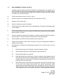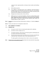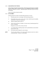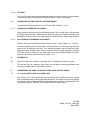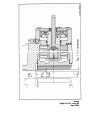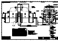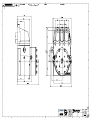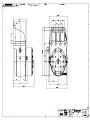
1
TWIFLEX
DISC BRAKE CALIPER
TYPE ‘VKSD’ BASE MODEL
INSTALLATION, OPERATION
AND
MAINTENANCE INSTRUCTIONS
M1438
AMENDMENT AND REVISION RECORD - M1438
SIGNATURE AND DATE
WHEN AMENDMENT ISSUED
AMENDMENT NUMBER
ISSUE AND DATE
13325
01
August 2004
02
April 2005
(i)
CONTENTS
Page
1.
Specification
1.1
1.2
1.3
General description
Detail specification
Monitoring units
2.
Installation & Adjustment
2.1
2.2
Installation
Initial Adjustment
3.
Maintenance
3.1
3.2
3.3
3.4
3.5
3.6
3.7
3.8
3.9
3.10
3.11
Running-in period
Maintenance inspection programme
Adjustment for friction pad wear
Friction pad replacement
Hydraulic supply failure
Mechanical retraction
Loss of braking force
Removal and replacement of caliper half
Replacement of seals 'in-situ'
Replacement of springs
Ships shaft brake operation
2
3
5
7
7
9
10
11
12
12
13
13
14
15
16
18
4. Rotabolts
18
5. Conversion of VKSD 119/62 into VKSD 64/28 or vice verse
18
Appendix 1. Spares
Appendix 2. Operational sequence (including figs. 1 – 5)
G1354 Data Sheet (weak spring detection)
G1457 Performance curves of VKSD 119/62
G1458 Performance curves of VKSD 64/28
G1459 Combined performance curves of VKSD 119/62 and VKSD 64/28
20
21
28
29
30
31
List of drawings:
VKSD 119/62 Caliper General Arrangement and Installation
VKSD 64/28 Caliper General Arrangement and Installation
VKSD 119/62 Spring module assembly
VKSD 64/28 Spring module assembly
A01517
A01518
A01519
A01520
References:
VKSD Performance Curves – Explanatory Notes.
V Type Monitor Unit I.O & M Manual.
S1025
M1438
Page 1 of 31, Issue 02
April 2005
1.
SPECIFICATION
1.1
GENERAL DESCRIPTION
THE OPERATIONAL SEQUENCE is illustrated in Appendix 2. Numbers in brackets
refer to item nos. on Drg. No. A01519 for VKSD 119/62 and A01520 for VKSD 64/28.
The VKSD disc brake caliper is a spring applied, hydraulically retracted unit which may
be used on any disc having a diameter of at least 1.0m and a thickness of 20mm or
greater. There is no upper limit on diameter or thickness. Braking torque may be
controlled by any combination of air gap setting, varying shim thickness, or by the use
of hydraulic backpressure during braking. The caliper consists of two halves which are
mounted each side of a mounting plate or pedestal by means of 4 M24 tie rods and 3
M16 bolts. No special bleeding arrangements are required for mounting at any angle
as the fluid is almost entirely evacuated when the hydraulic pressure is fully released
with the pads fully wound back.
The braking force is applied by the disc spring packs (25) through spring guides (4)
and thrust screws (3) to the pressure plates (2) and hence to the friction pads. The
calliper is available in two models: the VKSD 119/62 with 5 pairs of disc springs per
module, and the VKSD 64/28 with 7 single disc springs per module. Conversion of
model VKSD 119/62 into VKSD 64/28 is possible and is described in Section 5. The
pads are kept in position by pad retraction hooks (13) on to the pressure plates (2),
which transmit the braking force to the main housing (1).
The housing contains the spring chamber. The hydraulic retraction cylinder (6) is
spigoted to the housing and the bleed screw and inlet port can be positioned by
releasing two set screws (55) and rotating the cylinder. The hydraulic retraction piston
(5) is held onto the spring-guide by means of a piston collet (8) with its retainer (9).
Brake rating can be varied by removing or adding shims (27,28) between piston (5)
and end cover (7). Gap adjustment is manual and is effected by turning the hexagonal
adjusting spindle (10). Nominal gaps are as given on the drawing. Maintaining the
correct gap ensures that the braking torque is effectively constant and minimises the
stress range for the springs, leading to an extended fatigue life. Reduction in torque
due to a 1mm stroke increase is about 6% to 8% for the VKSD 119/62 and 4% to 15%
for the 64/28. Failure of an individual spring would result in a substantial loss of braking
torque in the affected caliper (see 3.7d).
Connections are provided for piping away any oil leakage.
Optional monitoring units are available which indicate:
a)
Full retraction of the brake - i.e. correct functioning of the hydraulic system. In
conjunction with a suitable hydraulic pressure switch this facility can be used to
give an indication of spring breakage. (see section 3.7 (d))
b)
Need for adjustment for pad wear.
c)
Need for pad replacement.
M1438
Page 2 of 31, Issue 02
April 2005
1.2
DETAIL SPECIFICATION
1.2.1
The VKSD series has a special operational feature called 'Parked-Off' position. This is
made possible by having a piston stoke long enough to permit the disc springs to fully
expand. Hence no internal spring loads exist in this condition. Yet the brake pads can
be retracted to be within the mounting face and 11.5mm (0.45") clear of the disc. This
brings the following advantages:
a)
The unit can be shipped without a retraction tool and with the cylinder endcover and monitoring unit in position.
b)
The unit can be installed without the need for hydraulic pressure.
c)
The pads can be safely exchanged without a retraction tool and with the
hydraulics at zero pressure.
d)
Hydraulics can be operated and tested, and air gap set without placing
unbalanced axial load on the brake disc and shaft.
e)
The module, including spring pack, can be safely assembled and
disassembled.
f)
In the case of hydraulic failure, the retraction tool is only required to release the
brake. Full retraction is not necessary as upon release the pad can be wound
back in the parked-off position, and the retraction tool removed.
g)
For 'ship-shafts' maintenance use, the brake when placed in the 'parked-off'
position cannot be applied accidentally or due to inadvertent operation or
hydraulic failure (see also 3.11). The 'parked-off' feature combined with a
separate cylinder allows:-
h)
Cylinder to be rotated to position the bleed, at any time, even after installation.
j)
Cylinder can be dismantled, permitting replacement of seals and cylinder
wearing surface 'in-situ'.
M1438
Page 3 of 31, Issue 02
April 2005
1.2.2.
BRAKING FORCE & TORQUE (SEE DRG. A01517 and A01518 AND
CURVES G1457 and G1458)
The braking force 'F' (kN) acting tangentially on the disc is given by F = 2 x µ x S
where µ is the friction coefficient of the brake pad and S is the spring pack thrust (kN)
(1bf). Nominal values for braking force are given on the drawings together with the
appropriate air gap settings; please note that these values are based on a coefficient
of friction µ = 0.4.
This value can only be achieved under ideal conditions. Factors which influence µ are:
- material and surface finish of disc, amount of surface contact (after bedding in),
cleanliness of pad and disc, humidity, temperature and grade of pad material, and
finally, rubbing speed. In a near static application for example µ can be as low as 0.15.
Braking torque T (kNm) is given by T = F x (R - 0.095m) where R is the outside radius
of the disc in metres.
(T lbf.ft = F lbf x (R - 0.312)ft).
The braking force obtained is also dependent on the gap setting and the amount of
shims fitted as is shown on performance curve G1457 and G1458. Please note that
these curves are also based on µ = 0.4 and that a service factor has to be applied for a
particular application. Also shown on these curves is the fatigue life for (99%) of the
springs for a particular gap setting. See Publication S1025 for an explanation of how to
read the curves.
1.2.3
RETRACTION CYLINDERS STANDARD.
Diameter = 150mm (5.9 ins)
Spring guide diameter = 70mm (2.756 ins)
Effective area = 13823mm2 (21.425 in2)
Hydraulic pressures for brake release and full retraction are given on the drawing for
the nominal gap setting. For other gap settings or shim settings these pressures can
be read from the curves. (See Publication S1025 - Performance Curves - Explanation)
In order to avoid overstressing the 8 M10 set screws on the end cover it is
recommended that the maximum hydraulic pressure shall not exceed the retraction
pressure by more than 25 bar (363 psi).
Recommended hydraulic fluid is a good quality mineral oil such as Shell 'Tellus 37' or
an approved fire resistant type.
Fluid inlet connections are 3/8” BSP (G3/8) and fittings are normally provided to
connect the cylinders by means of 12mm o/d. x 1.5mm seamless steel tubing to DIN
2391/C.
1.2.4
FRICTION PADS
Friction pads in non-asbestos material are supplied; some types may have a lower
coefficient of friction. Initial thickness of the pads (including back plate) = 22mm
(0.866in).
M1438
Page 4 of 31, Issue 02
April 2005
Total pad area (two pads) = 694 cm2 (107.5 in2)
The permissible wear on these brakes is 10 mm (0.39 ins) with a wear life of 25 000
MJ. For pad replacement see Section 3.4.
1.2.5
MATERIALS AND QUALITY ASSURANCE
The housings, pressure plates and cylinders* on the VKSD are castings of SG iron, to
BS 2789, grade 420-12. Other metal components are steel. Calipers can be supplied
with non-destructive test (NDT) certificates for all critical components, if required. The
main hydraulic seals are PTFE; 'O' rings are nit rile rubber.
* Some cylinders may be steel.
Each caliper is fully tested after assembly and a test certificate issued.
1.3
MONITORING UNITS
Monitoring units are supplied as an option; a typical 3-function model, part number
7700660 (drg. no. A22444) is described below. The unit is fitted to the cylinder end
cover. Each unit contains three micro-switches, which may be used to operate warning
lamps or other indicating devices. One switch (SWC) is operated by a collar on the
adjusting spindle, the other two are operated by a spring loaded actuator which bears
directly on the back of the hydraulic piston (SWA, SWB). A 20mm conduit entry is
provided. All switches are sealed to IP67 and suitable for temperature down to -500C.
The Box itself is also sealed to be splash proof. The functions and connections of the
switches are as follows:
SWA Terminals 2 (NC) 3 (NO)
Switch operates when brake is fully retracted, indicating correct functioning of the
hydraulic system, and providing "brake-off" warning.
SWB Terminals 5 (NC) 6 (NO)
Switch closes, with brake on, when stroke has increased due to pad wear sufficiently to
required adjustment. Normally set to indicate 1mm wear.
M1438
Page 5 of 31, Issue 02
April 2005
SWC Terminals 8 (NC) 9 (NO)
Switch closes when the pad requires replacement. Normally set to indicate 10mm (3/8
in) pad wear.
The switch settings may be adjusted to some extent to suit particular applications.
These units are supplied loose and correctly set, but should be checked for correct
adjustments after re-fitting to the caliper.
The switch ratings, in amperes, are as follows:
VOLTAGE
AC
DC
RESISTIVE
LOAD
TUNGSTEN LAMP LOAD
N/C
N/O
INDUCTIVE
LOAD
125
3
0.5
0.5
3
250
3
0.5
0.5
3
up to 15
3
3
1.5
3
30
3
3
1.5
3
50
1
0.7
0.7
1
75
0.75
0.5
0.5
0.25
125
0.5
0.4
0.4
0.05
250
0.25
0.2
0.2
0.03
For a full description see Publication M1105.
M1438
Page 6 of 31, Issue 02
April 2005
2.
INSTALLATIONS AND ADJUSTMENT
2.1
INSTALLATION
Refer to Drawing A01517 for VKSD 119/62 and Drawing A01518 for VKSD 64/28.
Ideally, two calipers should be used on each disc, mounted diametrically opposite each
other, in order to neutralise the braking torque reaction forces on the shaft bearings.
Any other position can also be catered for, as the bleed screw on the cylinder can be
indexed to any position, after releasing the two set screws (55); the set screws should
be retightened to 6Nm (4.5 lbf.ft)
Brake mounting plates or pedestals should be of adequate strength and rigidity, and
must be flat, and parallel to the disc surface. Each caliper is secured by four M24 tie
bolts and three M16 bolts, (can be supplied by Twiflex) which should be tightened to a
minimum torque of 775Nm (575 lbf.ft) and 200 Nm (148 lbf.ft) respectively.
NOTE:
VKSD 119/62 calipers subject to REVERSING BRAKING LOADS over 70kN
must be provided with one M24 ‘fitted’ tie rod at either end of the row of 4 tie
rods. One end hole in the mounting plate must also be machined to
Ø25(+0.025/+0.000).
The mounting plate should be positioned with respect to the disc as shown on the
drawing with the mounting surfaces lined up with, but 6 mm proud of, disc rubbing
surface.
Sufficient space should be allowed for access to the calipers for routine inspection and
maintenance and for pad renewal as indicated on drawings A01517 and A01518.
Calipers are supplied in the "parked off" position in which the springs are fully relaxed
and the pad is retracted within the mounting face. When the caliper halves have been
bolted into position, the hydraulic supply should be connected and all air bled from the
system using the bleed screws (19).
2.2
INITIAL ADJUSTMENT
a)
With the bleed screws closed the cylinders may be pressurised to a maximum of 25
bar (360 psi) above the retraction pressure as given on the drawing. In the fully
pressurised condition the back of the spring guide (4) should be 2.0 mm (0.079 in) from
the inner face of the cylinder end cover (7) or shims (27,28) where fitted.
M1438
Page 7 of 31, Issue 02
April 2005
b)
The Air Gap should be set as follows:
Remove the M5 screws in the spindle locking plate (12) and disengage its slot from the
hexagon spindle (10). Using a 19mm AF spanner turn one of the hexagonal adjusting
spindles (10) clockwise until the pad is in firm contact with the disc, then back off by
2/3rds of a turn for 2mm (0.080 in) air gap, 1 turn for 3mm (0.120 in) air gap or 1 1/3
turns for 4mm (0.160 in) air gap. (The pitch of the thrust screw (3) is 3mm (0.12 in)).
The actual retraction dimensions will be slightly greater when the caliper deflects under
load. Repeat the setting procedure on the other side of the caliper. Operate the caliper
and check that the air gap or stroke is correct; Adjust if required. The minimum
adjustment which can be made is 1/6th of a turn = 0.5mm (0.020 in) by leaving the
locking plate in the same position or 1/12th of a turn = 0.25mm (0.010 in) by removing
the M5 screws and inverting the locking plate (12).
c)
Please note that the correct shim stack height will have been fitted, commensurate with
the brake performance required. The braking force can however be reduced by adding
shims or increased by removing shims.
Notes
i)
Maximum shim stack height is 7mm for VKSD 119/62 and 6mm for VKSD
64/28, both with the step on the end cover (7) inwards. Exceeding these
amounts will under stress the disc springs and shorten their life.
WARNING
The position of the step on the end cover (7) of the VKSD 119/62 MUST
ALWAYS BE INWARD - NEVER OUTWARD, as this would severely
overstress the disc springs.
ii)
Always remove or add the same amount of shims on each side of the caliper.
iii)
Always, after refitting end cover (7), retighten set screws (47) evenly in turn to a
torque of 50Nm (36 lbf.ft).
d)
The drain connections (two each side of the caliper) can now be piped away to waste.
It may be convenient to use flexible tubing, and if transparent tubing is used any
leakage will be immediately apparent.
M1438
Page 8 of 31, Issue 02
April 2005
3.
MAINTENANCE
3.1
RUNNING-IN PERIOD
For the first full week of operation make a DAILY CHECK of the following items:
a)
Note:
Hydraulic Fluid Leakage. Note and report any evidence of fluid leakage. If the
leakage occurs at the pipe connections or at the bleed screws, tighten as
appropriate, carefully wipe away spilled fluid and check for further leaks with
brakes off.
The air gap is measured between pad and disc at full retraction. The
stroke is the air gap plus caliper deflection and is the movement of the
adjusting spindle from brake 'on' to full retraction, measured with
respect to the end cover (item 7).
If friction pads become fouled with fluid, they must be replaced after curing the
leak and the disc(s) wiped clean. A very slight seepage of oil past seals (29)
(30) is normal, but should not be such as to cause a flow in the drain pipes.
b)
Observe brake operation including smooth retraction and application of brake
pads. Note and report any unusual observations.
c)
Check condition of the brake paths. They should remain smooth and free from
contaminants, for example rope lubricant. Remove any deposits.
d)
At the end of the running-in period, check the security of all bolted connections
and pipe connections.
The caliper mounting bolts should be paint marked to provide a visual security
check.
M1438
Page 9 of 31, Issue 02
April 2005
3.2
MAINTENANCE INSPECTION PROGRAMME
After the running-in period the following schedule should be followed in addition to any
statutory requirements.
MAINTENANCE SCHEDULE
ITEM
WEEKLY
a) Check for hydraulic fluid leakage
x
(note I)
b) Observe brake operation
x
(note ii)
c) Clean calipers of accumulated
deposits
MONTHLY
PERIODIC
x
d) Clean brake paths on disc
x
(note iii)
e) Observe bolt security
x
(note iv)
f) Note and record brake pad
thickness
x
(note v)
g) Note and record brake pad
movement, (stroke). Adjust if
required.
x
(note vi)
h) Check availability and condition
of spares and tools
x
j) Remove and inspect brake pads
(see 3.4)
x
NOTES
(i)
See note (a) under "Running-in period" (3.1). Any appreciable flow from the drain pipes
indicates that one or more of the hydraulic seals needs replacing. This may be
conveniently done by replacing the complete half as in Section 3.8. However, if
servicing on site is essential, consult Section 3.9.
(ii)
See note (b) under "Running-in period".
(iii)
Under adverse conditions this may be required more frequently.
(iv)
Check that no movement has occurred at paint-marked bolts and test security of other
fasteners.
Note brake pad wear by measuring proximity of pad backing plate edges to disc, with
(v)
M1438
Page 10 of 31, Issue 02
April 2005
brakes on. A dimension of 2mm at any position indicates that the pad needs to be
replaced. Replacement thickness is 12mm (0.470 in) measured over backing plate.
New thickness is 22 mm (0.866in) over backing plate.
(vi)
Air gap is nominally as shown on the drawing or on the curves but is affected by disc
axial float and run-out and will vary by that amount. Actual stroke measured at the pad
will be greater, due to deflections of the caliper, and movement of the adjusting spindle
is the most convenient measurement. - See Publication S1025.
Where no monitoring units are fitted and when pad wear is very low (as is generally the
case), comparative checks of pad movement may be made monthly with accurate
measurements at less frequent intervals.
3.3
ADJUSTMENT FOR FRICTION PAD WEAR
The adjustment is made by turning the adjusting spindle (10) clockwise using a
suitable spanner. Adjustment can be made in 0.5mm (0.020 in) increments (1/6th of a
turn) by leaving the locking plate in the same position or in 0.25mm (0.010 in) by
inverting the locking plate.
a)
Determine adjustment required to bring piston stroke into line with original gap setting
(see note (vi), section 3.2 above).
b)
Remove the M5 screws from spindle locking plate (12) and slide it back to disengage
spindle.
c)
Turn spindle clockwise by one 'flat' (600) for 0.5mm (0.020 in) adjustment, two 'flats'
(1200) for 1mm (0.040 in) etc. Should adjustment required be 0.25mm (0.002in) then
the locking plate must be inverted for 1/12 turn.
d)
Replace locking plate and tighten M5 screws to 6Nm (4.5lbf.ft) so locking the adjusting
spindle.
e)
Repeat for opposite pad; pads should always be adjusted in pairs.
M1438
Page 11 of 31, Issue 02
April 2005
3.4
FRICTION PAD REPLACEMENT
Brake pad replacement is indicated when:-
a)
The monitor switch (where fitted) has signalled that pad is fully worn.
b)
Top of the plunger (14) is level with housing face.
c)
The backing plate edges are 2mm or less from disc.
d)
If the pad thickness has more than 2mm (0.08 in) taper, as measured at the four
corners, it should be replaced, even if not fully worn.
e)
Minimum pad thickness is 12mm (0.47in).
Before removing brake pads, secure the disc against rotation. Retract brakes fully,
hydraulically, and as a SAFETY measure place the brake in the 'parked-off' position by
turning the adjusting spindle fully anti-clockwise. The hydraulic pressure may now be
released. Unhook the pad retraction hook (13) by inserting a large screwdriver in the
pad retraction plunger (14), depressing spring (24) and turning the hook through 1800.
The pad can now be removed, first by pushing it away from the pressure plate through
the holes provided, then by sliding it along the disc-rubbing surface.
Remove dirt using a clean dry cloth and note condition of pad friction surface, which
should be polished, uniformly marked and free of serious pitting. Replacement of the
pad is carried out by reversing the removal procedure, but first clean the pressure
plate. Ensure that pad is properly seated by turning adjusting spindle such that pad is
forced firmly against disc. Refit pad retraction hooks.
After fitting the pads the piston stroke must be reset as in Section 2.2 (Initial
Adjustment) paragraph (b).
3.5
HYDRAULIC SUPPLY FAILURE
The brake may be released by means of a hand pump connected direct to the feed
port. After the brake has been released the 'parked-off' position can be obtained by
turning the adjusting spindle fully anti-clockwise. The hand pump can then be removed.
M1438
Page 12 of 31, Issue 02
April 2005
3.6
MECHANICAL RETRACTION
The retraction tool kit, an optional, can be purchased separately.
The retraction tool should only be required to release the brake when a hand pump is
not available or there is a hydraulic failure, such as when the seals leak to such an
extent that the brake cannot be released by hand pump. The retraction tool should
then be used as follows:
a)
Remove end covers (7) complete with monitoring units, if fitted. Take care not to lose
any shims.
b)
With nuts (M12) already threaded onto the retraction screws, attach the retractor flange
to the hydraulic piston (5). See scrap view on drawings A01519 and A01520.
c)
Release brake by tightening the nuts evenly in turn.
d)
Turn the adjusting spindle fully anti-clockwise thus placing the brake in the 'Parked-Off'
position.
e)
The retractor flange may now be removed, by loosening the nuts evenly in turn.
f)
Always remove retractor flange before resuming normal operation.
3.7
LOSS OF BRAKING FORCE
Possible causes are:-
a)
Contaminants on surface of pads or disc, especially lubricants,
b)
Higher than normal hydraulic back pressure when brakes are applied.
c)
Increased stroke (due to pad wear, necessitating adjustment; or incorrect adjustment).
M1438
Page 13 of 31, Issue 02
April 2005
d)
Damaged or broken disc spring or springs
Where the monitoring switch assembly is fitted any significant reduction in the force
developed by a spring can be detected by the addition of a pressure switch to the
hydraulic fluid supply, as shown in data sheet G1354. If the above system is not used,
spring force can be checked by use of a calibrated oil pressure gauge suitable for the
maximum back pressure employed. Pressures required for full retraction are given on
the drawing or can be taken from the curves. Springs should be changed if the
reduction in pressure is 12.5% or more. Normally the easiest procedure would be to
remove the complete caliper half as in 3.8 below and return it to Twiflex for service or
replacement. However, for cases where this is not possible the procedure for seal
replacement is described in section 3.9 and replacement springs is described in
section 3.10.
3.8
REMOVALS AND REPLACEMENT OF CALIPER HALF
a)
Balance load and secure the installation from rotation.
b)
Remove monitoring units if fitted.
c)
Release the brakes hydraulically or mechanically and place the brake in the 'ParkedOff' position by turning the adjusting spindle fully anti-clockwise; hydraulic pressure
may then be released.
d)
If the brake pads are re-usable, remove them and put them in a dry clean place;
otherwise ensure that spares are available.
e)
Disconnect the hydraulic unions, controlling the fluid loss.
f)
Support the weight of the caliper half to be removed.
g)
Unscrew and remove the four M24 tie rod nuts and remove the three M16 mounting
bolts.
h)
Carefully slide the caliper half from the tie rods.
j)
Replacement of the caliper half is the reverse of removal. It is essential to preload the
M24 bolts to 188 kN (42300 lbf) by torquing to 775 (575 lb.ft). The M16 bolts should be
torqued to 200Nm (148lb.ft) See Note under 2.1 on calipers subject to reversing loads.
M1438
Page 14 of 31, Issue 02
April 2005
3.9
REPLACEMENT OF SEALS 'IN SITU'
Leakage of large cylinder seal (29) is indicated by oil seeping from the cylinder cover
drain. Leakage of rod seal (30) is indicated by oil seeping from the 1/8" BSP holes at
the sides of the housing fitted with plugs (58) on delivery. At least one plug, normally
the lower one, must be removed.
a)
Follow instructions as under 3.8 a,b,c, and e.
b)
Remove end cover (7) complete with bolts (47) and shims (27-28).
c)
Slacken off set screws (55).
d)
Remove retaining ring (40) from piston.
e)
Retract and remove collet retainer (9) by inserting M4 x 40 screws in the tapped holes
in this retainer.
f)
Remove split piston collet (8). It may be necessary to free the segments by tapping
them towards the pad end of the caliper. Note that collet segments are marked with a
batch number, e.g. B/20.
g)
Remove cylinder (6) and piston (5) together, by means of bar bolted to M12 retraction
holes in piston. 'O' ring (36) may be reused unless severely damaged.
h)
Take assembly to work bench and carefully remove piston (5).
j)
Inspect wear surfaces, seals, wear rings and 'O'-rings for damage and refurbish or
replace as necessary.
k)
Re-assembly is generally as dismantling procedure but in reverse order; note the
following:i)
Exercise great care not to damage seals and wearing surfaces.
ii)
Clean wearing surfaces on spring guide (4) and cylinder (6).
iii)
First assemble piston into cylinder.
iv)
Note that cylinder seal (29) has to be 'sized' by means of the cylinder, and rod
seal (30) by means of a tool, with a diameter of 69.970/69.940 (Ø 70f7) with a
chamfer of 8mm (0.3 in) long @ 150 blended into this diameter; surface finish to
be 0.4 microns (16 micro-ins).
v)
Slide cylinder-piston assembly onto spring guide, ensuring that cylinder spigot
is fully home into housing. Move piston into cylinder so that split collet
segments (8) can be entered into groove in spring sleeve. Refit 'O'-ring (35) to
hold segments in place. Insert collet retainer (9) and apply some air pressure
to the cylinder port to 'blow' piston into place. Collet segments should be
M1438
Page 15 of 31, Issue 02
April 2005
replaced in their original positions, referring to batch number and identifying
marks.
vi)
Refit retaining ring (40).
vii)
Turn cylinder so that bleed screw (19) is uppermost. Note that thread at
hydraulic feed port and at bleed screw port are the same size; hence adaptor
(20) and bonded seal (61) can be removed to port which is nearest top and
thus save turning cylinder an unnecessary amount.
viii)
Retighten two set screws (55) to 6 Nm (4.5 lb.ft).
ix)
Refit end cover (7), (note correct position - see note 1), with monitoring unit if
fitted, taking care to enter the 3 tension pins (42) into the holes in the spring
guide. Tighten set screws (47) evenly in turn to a torque of 50 Nm (36 lbf.ft).
Refit external 'O' Ring (36). Finally reconnect hydraulic pipes, bleed and,
readjust brakes as under 2.1 and 2.2
Note 1 Note position of end cover (9) and refit as shown on drawing, i.e. flat side is always on
outside.
Note 2 Tension pins (39) have to be tapped into inside of lid.
3.10
REPLACEMENT OF SPRINGS
3.10.1
DISMANTLING
a)
Proceed as under 3.8 (a) to (h) and transfer caliper half to workshop.
b)
Proceed as under 3.9 steps (b) to (f).
c)
The pressure plate (2), thrust screw (3) and spring guide (4) with springs (25)
can now be removed from the housing.
d)
Alternatively the pressure plate (2) and thrust screw (3) can be removed first by
rotating the latter clockwise by means of the adjusting spindle (10).
The spring guide (4) with springs (25) can then be removed for inspection.
Note:
Take great care not to damage the rubbing surface for the rod seals (29). Keep springs
in their order as assembled if possible.
M1438
Page 16 of 31, Issue 02
April 2005
3.10.2
NON-DESTRUCTIVE TESTING
If the springs are visually sound an N.D.T. method may be employed. It is essential
that the surface finish of the disc springs is not damaged by electrical contacts,
sparking or otherwise, so an N.D.T. should be adopted, which does not give rise to any
such danger.
Inspect other parts as may be required.
3.10.3
RE-ASSEMBLY
Follow generally the reverse of the dismantling procedure, but note:
i)
Exercise great care not to damage seals and bearing surfaces.
ii)
Re-assemble spring in the reverse order to that in which they were originally
assembled (to extend their fatigue life).
iii)
Observe assembly notes under 3.9.
iv)
Clean wearing surfaces of cylinder (6), thrust screw (3) and spring guide (4)
before re-assembly.
Retighten set screws (55) to 6 Nm (4.5 lbf.ft).
NOTE:
v)
It is essential when reinstalling caliper half to preload M24 tie rods and M16
bolts as under 3.8(j).
vi)
Re-fit brake pads and adjust for correct air gap.
The disc spring bearing on the spring guide abutment must do so with its
smallest diameter, as shown on the drawing.
M1438
Page 17 of 31, Issue 02
April 2005
3.10.4
TESTING
Carry out functional testing and operational testing as may be required. Check settings
of monitoring units (if used) after refitting the caliper. Adjust if necessary.
3.11
OPERATION AS 'SHIP SHAFTS' HOLDING BRAKE
It is assumed that the brakes are in the "Parked Off" Position - 1.2.1g.
3.11.1
HYDRAULIC PRESSURE AVAILABLE
Apply hydraulic pressure and turn adjusting spindle (10) on both sides, until the pads
are firmly against the disc. Releasing the hydraulic pressure will apply the brake, and
Braking Force will be as for zero gap setting as indicated for the shim height as fitted.
3.11.2
NO HYDRAULIC PRESSURE AVAILABLE
Remove end cover and fit mechanical retraction tools - see section 3.6 a, b, and c.
Continue tightening the nuts until piston is fully retracted, i.e. when spring guide (4) is
within 8 mm of retraction tool face. Turn adjusting spindles until the pads are firmly
against the disc. Releasing the nuts on retraction bolts will apply the brake. Braking
Force will be as for caliper at zero gap setting at no shim height. Braking force will,
however, be affected by the factors as under 1.2.2.
4.
ROTABOLTS
4.1
Special Tie bolts are available, optionally, with a ‘Rotabolt’ tell-tale at one end.
This tell-tale can be rotated by hand when the pre-load is below specification and
cannot be rotated when the pre-load is correct.
5.
CONVERSION OF VKSD 119/62 INTO VKSD 64/28 OR VICE VERSA
5.1
To convert VKSD 119/62 into VKSD 64/28
See Section 3.10.1 and remove the ten disc springs (25). Discard three disc springs
and re-assemble springs facing alternate directions, and with the disc spring bearing
on the spring guide abutment with its smallest diameter as shown on drawing A01518.
Add spacer, part no. 7952008, at the other end of the spring stack.
M1438
Page 18 of 31, Issue 02
April 2005
5.2
Follow further re-assembly instructions as under 3.9 and 3.10.3 and fit shims as
required up to a maximum of 4mm with the end cover (7) step outward or 6mm with the
cover step inward.
5.3
To convert VKSD 64/28 into VKSD 119/62
See section 3.10.1 and remove 7 disc springs and discard spacer. Add 3 disc springs,
part no. 2500154, and re-assemble springs into 5 pairs, facing alternate directions, and
with the disc spring bearing on the spring guide abutment with its smallest diameter as
shown on drawing A01517.
5.4
Follow further re-assembly instructions as under 3.9 and 3.10.3 and add or discard
shims as required up to a maximum of 7mm.
NOTE: Position of end cover (7) on VKSD 119/62 the flat side is on outside; on VKSD 64/28
the stepped side is on the outside for the higher capacity settings and to the insider for
the lower capacity settings.
5.5
Follow installation and adjustment instructions as under 2.1 and 2.2.
M1438
Page 19 of 31, Issue 02
April 2005
APPENDIX 1 TO PUBLICATION M1438
RECOMMENDED SPARES FOR VKSD SERIES
For each brake in use at remote sites or in marine installation, the following spares should be
carried:ONE SET OF BRAKE PADS
These are to be stored in a dry place away from contact with oil or grease.
Please order correct grade of friction material.
Component
Part No.
Qty.
IFI 75103 (non asbestos)
7080153-Z
2
Ferodo 3904F (non asbestos) STANDARD
70A0153-9
2
70A0153-AR
2
70M0228-AS
2
One set of seals
6000543
2
2 Part cylinder seal
6000428
2
2 Part rod seal
6000427
2
150 I/D
6000402
2
70 I/D
6000403
2
172 I/D
6000404
2
‘O’ ring 150 x 145 x 3
6000399
2
‘O’ ring 74 x 70 x 2.4
6000398
2
‘O’ ring 190 x 185 x 3
6000167
2
‘O’ ring 65 x 75 x 3
6000445
2
6000490
6000450
2
2
Pad –
Select
from :-
Dynamex/Ferodo D2013 - High
Temperature (non-asbestos)
Sintered
Bearing ring (piston)
Bearing ring (rod)
Bearing ring
Back-up ring
Quad ring seal
70 I/D
171.05 I/D
M1438
Page 20 of 31, Issue 02
April 2005
APPENDIX 2 TO PUBLICATION M1438
OPERATIONAL SEQUENCE (REF; FIGS 1 TO 5).
Brake 'Parked Off' (Fig.1)
The brake is supplied in the 'Parked-Off' position, so that it can be mounted with disc springs
fully relaxed and yet with brake pads 11.5 mm clear of disc.
Brake cannot come on accidentally and can be dismantled safely. Connect hydraulic feed and
bleed brake in this position.
To Operate Brake
-
Apply hydraulic pressure as for full retraction. This compresses disc springs. Thrust
screw and pressure plate will separate at 'A' (Fig. 2).
-
Check for oil leaks.
-
Turn adjusting spindle clockwise:- up to 5 turns max. On the VKSD 119/62; up to 7½
turns on the VKSD 64/28, thus closing the gap at 'A' (Fig. 3). The number of turns
depends on the number of shims fitted.
The brake is now operational with about 11.5 mm retraction.
To Set Correct Air Gap
-
Maintaining full retraction pressure, continue turning spindle clockwise until brake pad
is firmly up against disc (Fig. 4).
-
Slacken off brake by turning spindle anti-clockwise to obtain required air gap.
-
Thread pitch on thrust screw is 3 mm
e.g.
1/6 turn for 0.5mm Air Gap
1/3 turn for 1mm Air Gap
1/2 turn for 1.5mm Air Gap
1 turn for 3mm Air Gap etc.
1/12 turn for 0.25mm Air Gap can be obtained by inverting locking plate.
Releasing hydraulic pressure will now apply the brake.
M1438
Page 21 of 31, Issue 02
April 2005
APPENDIX 2 CONT/D
Replacing Brake Pads
Return brake to 'Parked-Off' position as follows:
-
Apply just sufficient hydraulic pressure to release brake
-
Turn spindle fully anticlockwise.
-
Release hydraulic pressure.
Sufficient space is now available to remove old pad and insert new pad.
Hydraulic Supply Failure
-
Release brake by means of hand-pump connected direct to feed port.
-
Turn spindle anti-clockwise to obtain 'Parked-Off' position.
Mechanical Retraction
-
Fit retraction tool (Fig. 5).
-
Release brake by turning nuts the same amount in turn.
-
Turn spindle anti-clockwise to obtain 'Parked-off' position.
M1438
Page 22 of 31, Issue 02
April 2005
M1438
Page 23 of 31, Issue 02
April 2005
M1438
Page 24 of 31, Issue 02
April 2005
M1438
Page 25 of 31, Issue 02
April 2005
M1438
Page 26 of 31, Issue 02
April 2005
M1438
Page 27 of 31, Issue 02
April 2005
M1438
Page 28 of 31, Issue 02
April 2005
M1438
Page 29 of 31, Issue 02
April 2005
M1438
Page 30 of 31, Issue 02
April 2005
M1438
Page 31 of 31, Issue 02
April 2005
Used on
A01519
A01520
Component
Item
Number
Quantity Remarks
Drawing
Number
Part Number
A32661
7952007
1
STEEL PLATE BS4360 GRADE 43A
GRADE 8.8, ZINC & YELLOW PASSIVATE
1
RETRACTOR FLANGE
2
SCREW, HEX. HEAD, M12 x 60
5300219
6
3
NUT, M12
5100189
6
Title
VKSD MECHANICAL RETRACTION TOOL KIT
Drawn
Date
AD
Alt No.
Checked
Issue
Assembly Drawing No.
A35035
Assembly Part No.
7903437
Installation Drawing No.
12-4-05
Schedule No.
01
Any loose fittings to be placed in a plastic bag and tied to unit
Z157/22
Sheet 1 of 1
Form No. DO/52-3
A
4
1
2
3
THIS DRAWING IS THE PROPERTY OF TWIFLEX LTD. IT MUST NOT BE LENT
COPIED OR DISCLOSED WHOLLY OR IN PART TO ANY PERSON WITHOUT WRITTEN
AUTHORITY FROM TWIFLEX LTD. DESIGN RIGHT SUBSISTS IN THE DESIGN OF
ARTICLES MANUFACTURED WHOLLY OR IN PART IN ACCORDANCE WITH THIS DRAWING.
USED ON
4
5
THIRD ANGLE PROJECTION
67A1541
A01517
67A1544
A01535
6
0
METRIC
10
7
50
8
9
10
12
13
14
REMOVE SHARP EDGES
DO NOT SCALE
100 mm
11
A
A
A
49
21
1
B
B
34
7
63
31
6
29
5
9
47
MECHANICAL RETRACTION DETAIL
TOOL KIT PART No. 7903437
TO BE PURCHASED SEPARATELY
SCHEDULE No. Z157/22
40
TIGHTENING TORQUE:
50Nm (36lb. ft)
19
20
8
61
C
42
G3/8(3/8"BSP) PORT FOR BLEED
SCREW (HYDRAULIC INLET AND
BLEED CAN BE INTER-CHANGED.)
C
58
G1/8 (1/8"BSP)
DRAIN PORTS
C
B
D
B
D
D
58
11
G1/8 (1/8"BSP)
DRAIN PORTS
12
54
USE LOCTITE
SCREWLOCK 222
ON ASSY. ITEM TO BE
REMOVED WHEN FITTING
MONITORING UNIT.
48
TIGHTENING TORQUE:
6Nm (4.5lb. ft)
A
35
37
38
30
36
32
25
3
4
39
33
2
E
SECTION
A-A
53
14
ASSEMBLE ITEM 14
IN POSITION SHOWN
WITH GROOVE IN LINE
WITH FACE OF HOUSING
ITEM 3 AS SHOWN.
NOTE PRESSURE PLATE,
ITEM 14, ADJUSTED
FULLY BACK.
F
G3/8 (3/8"BSP) PORT
FOR HYDRAULIC FEED.
CAN BE INDEXED TO
ANY POSITION
59
TIGHTENING TORQUE:
6Nm (4.5lb. ft)
27
55
17
28
13
41
SECTION
24
SECTION
D-D
C-C
PART SECTION SHOWING SHIMS
G
18
NOTES.
1. FOR PART IDENTIFICATION SEE SCHEDULE Z157/15
(SPRING MODULE BASIC PARTS, PART No.6701539)
45
2. (a) USE LITHIUM COMPLEX GREASE HTEP
(INDUSTRIAL PRODUCTS LTD)
16
SECTION
B-B
2
ITEM NO. QTY NAME
PART NO
1
1
HOUSING
7931996
2
1
PRESSURE PLATE
7931997
3
1
ADJUSTING SCREW
7953810
4
1
SPRING GUIDE
7951999
5
1
PISTON
7952000
6
1
CYLINDER
7951995
7
1
END COVER
7952001
8
1
PISTON COLLET
7952002
9
1
COLLET RETAINER
7952003
10
11
1
SPINDLE BEARING
7902224
12
1
SPINDLE LOCKING PLATE
7902225
13
2 PAD RETRACTION HOOK
7902005
14
2 PAD RETRACTION PLUNGER
7902006
15
16
1
THRUST WASHER
4700267
17
2 WASHER(VKSD)
4700274
18
2 WASHER
4700275
19
1
BLEEDSCREW, 1/8"BSP
6700381
20
1
ADAPTOR,3/8"BSP(M)x1/8"BSP(F)
7300662
21
1
LABEL
7901483
22
23
24
2 PAD RETRACTION SPRING
2500248
25
10 DISC SPRING
SEE Z157/3
26
27
1
SHIM 1mm
SEE Z157/3
28
1
SHIM 2mm
SEE Z157/3
29
1
CYLINDER SEAL, 150 O.D.
6000428
30
1
ROD SEAL, 70 I.D.
6000427
31
1
BEARING RING, 150 O.D.
6000402
32
1
BEARING RING, 70 I.D.
6000403
33
1
BEARING RING, 172 I.D.
6000404
34
1
O-RING, 150x145x3
6000399
35
1
O-RING, 74x70x2.4
6000398
36
1
O-RING, 190x185x3
6000167
37
1
O-RING, 67x75x3
6000445
38
1
BACK UP RING, 75 I.D.
6000490
39
1
QUAD RING SEAL, 171.05 I.Dx3.53 SECTI
6000450
40
1
RETAINING RING, 100 I.D.
4300195
41
3 GRIP RING,6 DIA
4300193
42
3 PIN, TENSION, 6DIAx50
3800183
43
44
45
1
SCREW, SOCKET CSK, M5x16
5500070
46
47
8 SCREW,HEX,HEAD,M10x30
5300192
48
4 SCREW, HEX. HEAD, M5x12
5300286
49
4 SCREW, HAMMER DRIVE No. 2
5600019
50
51
52
53
2 SETSCREW, HEX. SOCKET, M6x8
5400469
54
1
SETSCREW, HEX. SOCKET, M8x10
5400472
55
2 SETSCREW, HEX. SOCKET, M6x12
5400470
56
57
2 PLUG,3/8"BSP (TRANSPORT PURPOSES ONLY)
7300663
58
4 PLUG, 1/8" BSP
7300657
59
1
COUPLING, MALE STUD,3/8" BSPx12TUBE
7300664
60
61
1
SEAL, BONDED, 3/8" BSP
7301025
62
2 SEAL BONDED, 3/8" BSP (TRANSPORT PURPOSES ONLY) 7300148
63
1
COLLAR EYEBOLT, M16
1402353
C
D
E
F
G
(b) GREASE INNER AND OUTER ABUTMENT FACES OF ALL DISC SPRINGS.
3. ITEMS 57 AND 62 FITTED FOR TRANSPORT PURPOSES. THESE ARE TO BE REMOVED AND ITEMS
19, 20, 59 AND 61 FITTED ON INSTALLATION
THIS
ISSUE
SCHEDULE Z157/13
H
03
03
XXXXX
02
13325
01
-
ISSUE
No.
ALT. No.
DIMENSIONS IN mm.
OPEN TOLERANCES
0.25
ANGLES
0.5
GENERAL M/C FINISH = 1.6 m
SURFACE FINISH IN MICRONS
10/06/11 CONVERTED TO NX ASSOCIATIVE DRAWING
ITEM 15,46,51 AND 52 DELETED.MECHANICAL RETRACTION
13/04/05 TOOL KIT PART No. 7903437 & SCHEDULE No. Z157/22 ADDED
25/06/04
DATE
-
DESCRIPTION
GRID
REF.
ALTERATION
1
TWIFLEX LIMITED
AMPTHILL ROAD
BEDFORD MK42 9RD
2
e.g.
4
5
6
7
8
9
10
R.E.G.
MATERIAL
= 2 MICRONS
(0.002mm) CLA
( = 80 MICRO-INCHES CLA)
DATE
11
25/06/04
-
xx
PART
No.
FINISH
2
SCALE
3
SPRING MODULE ASSEMBLY
VKSD119/62, BASE MODEL
CHECKED
DRAWN
INERTIA
DESCRIPTION
CERT'D
WEIGHT
kg m 2
73
kg
6701537
-
DRG.
No.
1:1
12
H
13
A01519
14
SHT 1 OF 2
FORM No DO/36-4
A
0
1
USED ON
2
3
4
THIS DRAWING IS THE PROPERTY OF TWIFLEX LTD. IT MUST NOT BE LENT
COPIED OR DISCLOSED WHOLLY OR IN PART TO ANY PERSON WITHOUT WRITTEN
AUTHORITY FROM TWIFLEX LTD. DESIGN RIGHT SUBSISTS IN THE DESIGN OF
ARTICLES MANUFACTURED WHOLLY OR IN PART IN ACCORDANCE WITH THIS DRAWING.
5
THIRD ANGLE PROJECTION
6
0
METRIC
10
50
7
8
9
10
12
13
14
REMOVE SHARP EDGES
DO NOT SCALE
100 mm
11
A
A
180.0
238.6
163.0
60.0
60.0
60.0
91.0
57.0
32.5
57.0
B
95.0
50.0
19.9
B
C
D
80.0
D
125.0
339.9
25.0
C
E
100.0
E
91.0
5.0
134.0
F
F
184.4
216.0
275.5
282.3
G
G
THIS
ISSUE
H
03
DIMENSIONS IN mm.
OPEN TOLERANCES
0.25
ANGLES
0.5
GENERAL M/C FINISH = 1.6 m
SURFACE FINISH IN MICRONS
TWIFLEX LIMITED
AMPTHILL ROAD
BEDFORD MK42 9RD
e.g.
2
3
4
5
6
7
8
9
10
R.E.G.
MATERIAL
= 2 MICRONS
(0.002mm) CLA
( = 80 MICRO-INCHES CLA)
DATE
11
25/06/04
-
xx
PART
No.
FINISH
2
SCALE
1
SPRING MODULE ASSEMBLY
VKSD119/62 BASE MODEL
CHECKED
DRAWN
INERTIA
DESCRIPTION
CERT'D
WEIGHT
kg m 2
xx
kg
6701537
-
DRG.
No.
1:1
12
H
13
A01519
14
SHT 2 OF 2
FORM No DO/36-4
A
0
1
2
3
THIS DRAWING IS THE PROPERTY OF TWIFLEX LTD. IT MUST NOT BE LENT
COPIED OR DISCLOSED WHOLLY OR IN PART TO ANY PERSON WITHOUT WRITTEN
AUTHORITY FROM TWIFLEX LTD. DESIGN RIGHT SUBSISTS IN THE DESIGN OF
ARTICLES MANUFACTURED WHOLLY OR IN PART IN ACCORDANCE WITH THIS DRAWING.
USED ON
4
5
THIRD ANGLE PROJECTION
67A1542
A01518
67A1545
A01536
6
0
METRIC
10
7
50
8
9
10
12
13
14
REMOVE SHARP EDGES
DO NOT SCALE
100 mm
11
A
A
A
28
28
49
41
21
1
B
PART SECTION SHOWING SHIMS
END COVER POSITION 'A'
SEE NOTE 4
34
7
6
31
B
PART SECTION SHOWING SHIMS
END COVER POSITION 'B'
SEE NOTE 4
29
5
ITEM NO QTY NAME
PART NO
1
1
HOUSING
7931996
2
1
PRESSURE PLATE
7931997
3
1
ADJUSTING SCREW
7953810
4
1
SPRING GUIDE
7951999
5
1
PISTON
7952000
6
1
CYLINDER
7951995
7
1
END COVER
7952001
8
1
PISTON COLLET
7952002
9
1
COLLET RETAINER
7952003
10
11
1
SPINDLE BEARING
7902224
12
1
SPINDLE LOCKING PLATE
7902225
13
2 PAD RETRACTION HOOK
7902005
14
2 PAD RETRACTION PLUNGER
7902006
15
16
1
THRUST WASHER
4700267
17
2 WASHER(VKSD)
4700274
18
2 WASHER
4700275
19
1
BLEEDSCREW, 1/8"BSP
6700381
20
1
ADAPTOR,3/8"BSP(M)x1/8"BSP(F)
7300662
21
1
LABEL
7901483
22
23
24
2 PAD RETRACTION SPRING
2500248
25
7 DISC SPRING
SEE Z157/3
26
1
SPACER
SEE Z157/3B
27
28
1
SHIM 2mm
SEE Z157/3
29
1
CYLINDER SEAL, 150 O.D.
6000428
30
1
ROD SEAL, 70 I.D.
6000427
31
1
BEARING RING, 150 O.D.
6000402
32
1
BEARING RING, 70 I.D.
6000403
33
1
BEARING RING, 172 I.D.
6000404
34
1
O-RING, 150x145x3
6000399
35
1
O-RING, 74x70x2.4
6000398
36
1
O-RING, 190x185x3
6000167
37
1
O-RING, 67x75x3
6000445
38
1
BACK UP RING, 75 I.D.
6000490
39
1
QUAD RING SEAL, 171.05 I.Dx3.53 SECTI
6000450
40
1
RETAINING RING, 100 I.D.
4300195
41
3 GRIP RING,6 DIA
4300193
42
3 PIN, TENSION, 6DIAx50
3800183
43
44
45
1
SCREW, SOCKET CSK, M5x16
5500070
46
47
8 SCREW,HEX,HEAD,M10x30
5300192
48
4 SCREW, HEX. HEAD, M5x12
5300286
49
4 SCREW, HAMMER DRIVE No. 2
5600019
50
51
52
53
2 SETSCREW, HEX. SOCKET, M6x8
5400469
54
1
SETSCREW, HEX. SOCKET, M8x10
5400472
55
2 SETSCREW, HEX. SOCKET, M6x12
5400470
56
57
2 PLUG,3/8"BSP (TRANSPORT PURPOSES ONLY)
7300663
58
4 PLUG, 1/8" BSP
7300657
59
1
COUPLING, MALE STUD,3/8" BSPx12TUBE
7300664
60
61
1
SEAL, BONDED, 3/8" BSP
7301025
62
2 SEAL BONDED, 3/8" BSP (TRANSPORT PURPOSES ONLY) 7300148
63
1
COLLAR EYEBOLT, M16
1402353
63
9
47
40
19
TIGHTENING TORQUE:
50Nm (36lb. ft)
20
8
61
C
G3/8(3/8"BSP) PORT FOR BLEED
SCREW (HYDRAULIC INLET AND
BLEED CAN BE INTER-CHANGED.)
C
42
58
G1/8 (1/8"BSP)
DRAIN PORTS
C
B
B
D
11
58
G1/8 (1/8"BSP)
DRAIN PORTS
D
D
12
54
USE LOCTITE
SCREWLOCK 222
ON ASSY. ITEM TO BE
REMOVED WHEN FITTING
MONITORING UNIT.
48
TIGHTENING TORQUE:
6Nm (4.5lb. ft)
A
37
35
38
30
32
36
26
25
3
4
39
33
2
E
SECTION
G3/8 (3/8"BSP) PORT
FOR HYDRAULIC FEED.
CAN BE INDEXED TO
ANY POSITION
53
14
ASSEMBLE ITEM 14
IN POSITION SHOWN
WITH GROOVE IN LINE
WITH FACE OF HOUSING
ITEM 3 AS SHOWN.
A-A
59
17
F
24
CENTRE LINE OF 1/8" BSP
DRAIN PORTS IN HOUSING
13
SECTION
C-C
TIGHTENING TORQUE:
6Nm (4.5lb. ft)
G
C
D
E
F
G
NOTES.
18
55
1. FOR PART IDENTIFICATION SEE SCHEDULE Z157/15
(SPRING MODULE BASIC PARTS, PART No.6701539)
2. (a) USE LITHIUM COMPLEX GREASE HTEP
(INDUSTRIAL PRODUCTS LTD)
45
16
SECTION
MECHANICAL RETRACTION DETAIL
TOOL KIT PART No. 7903437
TO BE PURCHASED SEPARATELY
SCHEDULE No. Z157/22
B-B
(b) GREASE INNER AND OUTER ABUTMENT FACES OF ALL DISC SPRINGS.
2
3. ITEM 47 AND 62 FITTED FOR TRANSPORT PURPOSES. THESE ARE TO BE REMOVED AND ITEMS
19, 20, 59 AND 61 FITTED ON INSTALLATION
4. SEE THE PERFORMANCE DATA CHART ON DRAWING No. A01518
SHOWING END COVER POSITIONS 'A' AN 'B' REQUIREMENTS.
SECTION
H
THIS
ISSUE
SCHEDULE Z157/14
D-D
03
03
XXXXX
10/06/11 CONVERTED TO NX ASSOCIATIVE DRAWING
02
13325
ITEM 15,46,51 AND 52 DELETED.MECHANICAL RETRACTION
13/04/05 TOOL KIT PART No. 7903437 & SCHEDULE No. Z157/22 ADDED
01
-
ISSUE
No.
ALT. No.
25/06/04
DATE
-
DESCRIPTION
TWIFLEX LIMITED
AMPTHILL ROAD
BEDFORD MK42 9RD
GRID
REF.
ALTERATION
1
DIMENSIONS IN mm.
OPEN TOLERANCES
0.25
ANGLES
0.5
GENERAL M/C FINISH = 1.6 m
SURFACE FINISH IN MICRONS
2
e.g.
4
5
6
7
8
9
10
R.E.G.
MATERIAL
= 2 MICRONS
(0.002mm) CLA
( = 80 MICRO-INCHES CLA)
DATE
11
29/06/04
-
--
PART
No.
FINISH
2
SCALE
3
SPRING MODULE ASSEMBLY
VKSD64/28, BASE MODEL
CHECKED
DRAWN
INERTIA
DESCRIPTION
CERT'D
WEIGHT
kg m 2
kg
6701538
-
DRG.
No.
1:1
12
H
13
A01520
14
SHT 1 OF 2
FORM No DO/36-4
A
0
1
USED ON
2
3
4
THIS DRAWING IS THE PROPERTY OF TWIFLEX LTD. IT MUST NOT BE LENT
COPIED OR DISCLOSED WHOLLY OR IN PART TO ANY PERSON WITHOUT WRITTEN
AUTHORITY FROM TWIFLEX LTD. DESIGN RIGHT SUBSISTS IN THE DESIGN OF
ARTICLES MANUFACTURED WHOLLY OR IN PART IN ACCORDANCE WITH THIS DRAWING.
5
THIRD ANGLE PROJECTION
6
0
METRIC
10
50
7
8
9
10
12
13
14
REMOVE SHARP EDGES
DO NOT SCALE
100 mm
11
A
A
238.6
180.0
60.0
60.0
60.0
163.0
91.0
B
57.0
57.0
B
95.0
50.0
19.9
32.5
C
D
80.0
D
125.0
339.9
25.0
C
E
100.0
E
91.0
5.0
134.0
F
F
184.4
216.0
275.5
282.3
G
G
THIS
ISSUE
H
03
DIMENSIONS IN mm.
OPEN TOLERANCES
0.25
ANGLES
0.5
GENERAL M/C FINISH = 1.6 m
SURFACE FINISH IN MICRONS
TWIFLEX LIMITED
AMPTHILL ROAD
BEDFORD MK42 9RD
e.g.
2
3
4
5
6
7
8
9
10
R.E.G
MATERIAL
= 2 MICRONS
(0.002mm) CLA
( = 80 MICRO-INCHES CLA)
DATE
11
29/06/04
--
--
PART
No.
FINISH
2
SCALE
1
SPRING MODULE ASSEMBLY
VKSD64/28, BASE MODEL
CHECKED
DRAWN
INERTIA
DESCRIPTION
CERT'D
WEIGHT
kg m 2
--
kg
6701538
--
DRG.
No.
1:1
12
H
13
A01520
14
SHT 2 OF 2
FORM No DO/36-4
A
0