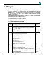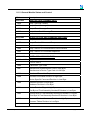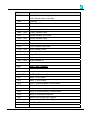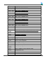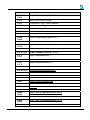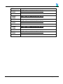
1
Maxiflex 8HI Hart Input Module
M1438A
SCOPE:
The HART protocol is a comprehensive open communications standard for
configuring and communicating with Smart field devices in industrial process
applications.
The Maxiflex M1438 8 Channel Hart Input Module is an Input Module that acts
as a permanent host interface device (primary master) on up to eight Hart
networks. The module is used to acquire data from the HART loops and to
make the data available for SCADA, data-logging etc. in the Maxiflex system.
Other specialised functions may be performed using the optional custom query
block mechanism.
This document describes the installation, set-up and use of the M1438A Hart
module in a Maxiflex system.
The reader is assumed to have a working knowledge of the Maxiflex system,
and in particular the use of Data Interchange Table Registers (DIT’s) for the
reading and writing of data in the module.
UMM1438R1.pdf
-2-
Copyright Omniflex
DATE
March 2012
REVISION
1
COMMENTS
Initial revision
COPYRIGHT AND PROTECTIVE NOTICES
1. The Copyright of this document and the associated drawings, is the property of Omniflex and
is issued on condition that it is not copied, reprinted or reproduced or transmitted in any form
or by any means, electronically, photocopying, mechanical or otherwise, nor its contents
disclosed, either wholly or in part, without the consent in writing of, or in accordance with the
conditions of a contract with Omniflex.
2. The publication of information in the document does not imply freedom from patent or other
protective rights of Omniflex or others.
3. Although every intention is made to ensure that performance figures and data are accurate the
company reserves the right to alter without notice any product or specification. Performance
figures and data must therefore be specifically confirmed by the company before they become
applicable to any tender, order or contract.
4. In the case of electrical components, enough data is included in the drawings to allow
maintenance of the equipment. However, if component availability or substitution information
is required please consult the factory for assistance, as it is impossible to include data on
every component in this document.
5. This product is sold without liability for consequential loss of any description.
UMM1438R1.pdf
-3-
Copyright Omniflex
Table of Contents
1.
Introduction..........................................................................................................................5
2.
Specifications ......................................................................................................................5
3.
The HART Protocol .............................................................................................................7
Background to the HART Protocol...................................................................................7
Application of the HART Protocol ....................................................................................7
Technical Features of the HART Protocol .......................................................................7
The M1438- 8 Channel HART. ........................................................................................8
3.1
3.2
3.3
3.4
4.
Installation ...........................................................................................................................9
4.1
Installing the 8HI on to a Maxiflex Base...........................................................................9
4.2
Connecting the HART Loops. ..........................................................................................9
4.3
Typical Connection Diagrams....................................................................................... 10
5.
Built in Resistor................................................................................................................. 10
6.
6.1
6.2
6.3
6.4
6.5
6.6
Operation.......................................................................................................................... 11
Hart Loop Independence .............................................................................................. 11
Philosophy of Operation ............................................................................................... 11
LED Indication............................................................................................................... 12
Device Identification...................................................................................................... 12
Burst Mode Operation................................................................................................... 13
Priority Polling Operation .............................................................................................. 14
7.1
7.2
7.3
7.4
Configuration .................................................................................................................... 16
Basic Configuration....................................................................................................... 16
Configuring Custom Query Blocks................................................................................ 16
Automatic Polling / Burst Mode Configuration .............................................................. 18
Automatic/Manual Polling Configuration....................................................................... 19
7.
8.
DIT Layout ........................................................................................................................ 20
8.1
Maxiflex Bus Interface Register Layout ........................................................................ 20
UMM1438R1.pdf
-4-
Copyright Omniflex
1. Introduction
The M1438A Hart ® 8HI module is an intelligent I/O module in the Maxiflex range of
products.
The M1438 plugs into an I/O slot on a Maxiflex base and independently interrogates field
devices on eight Hart networks, making the data available to the Maxiflex system.
This data may be accessed by the entire range of Maxiflex CPU’s. The method of access
may vary from CPU to CPU, and reference should be made to specific documentation for
these products for details of the implementation.
2. Specifications
Inputs/Outputs
Number of HART loops
8
Number of Field devices interrogated
15 max per HART loop
HART Operating Mode
Primary Master or Secondary Master
Loop Isolation Voltage
500V dc min.
Maximum Loop Voltage
35Volts
Minimum loop load resistance
230ohms
Maximum loop load resistance
1100ohms
HART Transmitter signal levels
400mV p-p min
600mV p-p max
HART Receiver sensitivity
120mV p-p min
2000mV p-p max
HART Receiver threshold (Must ignore)
80mV
DC load impedance
2microamps max at 60deg C 40Volts
AC load impedance
10 microFarads typical
UMM1438R1.pdf
-5-
Copyright Omniflex
HART Wiring Recommendations
Maximum Cable Impedance
R x C must be less than 65us
(e.g. 300ohms x 0.2uF = 60us)
(R includes load resistance)
(C includes field device capacitance)
Cable Type
Overall screen recommended
Individually screened pairs over 1500m
Loop Power Supply Maximum Ripple
0.2V p-p (47-125Hz)
Loop Power Supply Maximum Noise
1.2mV (500Hz – 10kHz)
Loop Power Supply Impedance
10ohms
Supported HART Commands as standard
Universal Commands
Command 0
Command 3
Identify Manufacturer, Device Type and
Revision Levels.
Read Current and four (predefined)
dynamic variables.
Other Commands
User Configurable
Up to 64 Custom Query Blocks may be
configured in the 8HI. Each query block
can address any HART device with any
command support supported by that
device.
The response is stored in its raw data
format in the Data Interchange Table
for interpretation by the user.
UMM1438R1.pdf
-6-
Copyright Omniflex
3. The HART Protocol
3.1
Background to the HART Protocol
HART is an acronym for “Highway Addressable Remote Transducer”.
The HART® protocol was originally developed by Rosemount Inc. but all rights in the
protocol have now passed to the HART Communication Foundation, and the HART
protocol is now freely available for general use.
There is an abundance of information on the HART protocol available from a number of
sources. The following Internet web-site is a recommended starting point for further
reading:
•
The HART Communication Foundation at http://www.hartcomm.org
3.2
Application of the HART Protocol
The HART protocol specifies a means for superimposing a digital messaging system on
top of a conventional 4-20mA instrumentation loop to allow the remote interrogation and
configuration of field devices. The operation of the HART system via the two wire 4-20mA
loop does not affect the accuracy of the dc current in the loop.
3.3
Technical Features of the HART Protocol
The HART protocol superimposes a Bell 202 Standard frequency-shift-keying signal at
1200 baud as an ac signal at a low level on the current loop.
HART is a master/slave protocol. The field devices act as slaves in the protocol and only
reply to requests addressed to them. Up to 15 slave devices may be connected on to a
single pair of wires. In this multi-drop configuration, the field devices disable their 4-20mA
signals and communication is exclusively via the HART protocol. When only a single slave
device is present, then both the 4-20mA and HART communication may operate
simultaneously.
The protocol allows for two masters to be present on a single HART loop. These are
typically a permanently connected control system (known as the primary master) and a
hand-held configuration device known as a HART Communicator (acting as a secondary
master).
The command messages defined in the HART protocol are broken into three groups:
1. The “Universal” commands are implemented in all field devices.
2. The “Common-Practice” commands provide functions common to many field devices,
but may not be installed in the device.
3. The “Device-Specific” commands provide functions that are unique to a particular
manufacturer’s device.
UMM1438R1.pdf
-7-
Copyright Omniflex
The HART “Device Description Language” (DDL) is a formal language that allows a
manufacturer to completely specify the communication interface to its HART equipped field
device. This includes a definition of accessible variables, commands and operating
procedures. It also includes a menu structure that a host device can use for a human
operator. Device Descriptions make it easy to upgrade master devices to support new
devices as they become available.
3.4
The M1438- 8 Channel HART.
The M1438 8HI HART module is equipped with eight independent HART primary master
interfaces. This allows this product to communicate independently with eight separate
HART loops at the same time.
The 8HI implements a subset of the universal commands and does not require DDL files to
configure the device. The list of commands implemented is defined later in this document.
The 8HI is designed to be self-configuring for ease of use. Once powered up, the 8HI
searches for HART devices on each of its eight HART interfaces and builds an inventory of
devices found. Various data elements are continuously and automatically read from the
device and stored in the Data Interchange Table (DIT) in the device for access by the rest
of the Maxiflex system. The 8HI in this mode uses HART commands 0 and 3 to extract the
most commonly used data from the field devices with no configuration necessary.
The 8HI is also provided with a custom query block mechanism. Up to 32 custom query
blocks may be configured per loop to perform specialised data manipulation on the
connected field devices using any of the command types supported by the field device.
UMM1438R1.pdf
-8-
Copyright Omniflex
4. Installation
4.1
Installing the 8HI on to a Maxiflex Base.
The M1438A 8HI must be inserted into one of the I/O positions of a Maxiflex Base.
Refer to the Maxiflex bases General Instructions (PN 98-8952-930-XXX) for more
detail on base layout, module insertion and module removal.
Figure 1: Layout of the 7I/O Master Base
4.2
Connecting the HART Loops.
Figure 2: Layout of the M1438 HART 8HI
UMM1438R1.pdf
-9-
Copyright Omniflex
Terminal-block connectors are provided for each HART interface. This interface is
completely isolated from the 8HI circuitry and therefore will not affect the
performance of a 4-20mA loop when connected.
The connection is not symmetrical, and correct polarity must be observed in order
not to affect the performance of the system.
It is NOT recommended that this connection be made while the 4-20mA loop is
active, as a small current upset may be observed when the 8HI circuit’s blocking
capacitors charge.
4.3
Typical Connection Diagrams
A
B
C
Two Wire Transmitter Connection
B
C
Four Wire Transmitter Connection
The HART NIM may be connected across A-B or B-C
5. Built in Resistor
Each Loop in the 8HI module has a built in 250 ohm 0.1% resistor. This resistor can be turned
ON and OFF by configuration. The configuration can be found under Configuration- Loop
Configuration- Loop n Configuration. The resistor can be turned ON and OFF by setting the
“Resistor” item to ON or OFF. This resistor can be used to terminate the HART loop.
UMM1438R1.pdf
- 10 -
Copyright Omniflex
6. Operation
6.1
Hart Loop Independence
The 8HI operates eight completely independent polling procedures, one for each HART
loop.
The following description applies to any of these HART loops.
6.2
Philosophy of Operation
In accordance with the Maxiflex inter-networking philosophy, the design of the M1438
8-Channel HART 8HI has been designed for maximum flexibility and ease of use.
The HART 8HI is designed as an interrogation device to be used for the purpose of
exchanging live plant data with a number of HART devices for data acquisition, monitoring
and data-logging applications.
The HART 8HI is not designed to replace the field device manufacturer’s recommended
set-up tools or procedures.
The configuration requirements for the 8HI have been kept to a minimum. In most
applications, no configuration at all is required, because the 8HI automatically identifies the
presence of field devices on the HART network, and begins polling for the most popular
field device configuration and dynamic data. This data is automatically stored in the 8HI’s
Data Interchange Table (DIT) from where it can be read by the rest of the Maxiflex system
in the conventional manner.
Upon power up, the 8HI begins an automatic polling sequence on each of the HART loops
(using universal HART command 0), and identifies any devices present on the loops. The
presence and identification of these field devices is made available in the DIT. Dynamic
data is then read on a regular basis (using universal HART command 3) from these
devices and is made available in the DIT.
The 8HI continues to poll on a regular but infrequent basis for the presence of any
additional field devices in the loop (using universal HART command 0), and automatically
begins polling these devices (using universal HART command 3) when found.
If a device is removed from the loop, then this is detected and the DIT updated
accordingly.
UMM1438R1.pdf
- 11 -
Copyright Omniflex
6.3
LED Indication
Name
8HI OK
Colour
GREEN
H1 – H8
GREEN
Indication
Steady ON - module healthy
OFF or Flashing – module unhealthy (except on startup)
Polled Mode
Slow Flash: Polling for devices on the loop. No devices
found yet.
Steady ON: Healthy communication with all configured
devices.
Fast Flash: Communicating with devices on the loop but
devices present does not equal configured devices.
Burst Mode
OFF: No communications present.
Steady ON: Healthy communication from the configured
device.
Slow Flash: Receiving burst packets from a device not
configured.
Note that the 8HI module always polls for new devices. This means that the H1-H8 LED’s
may flash continuously, even there are no devices connected to that loop.
6.4
Device Identification
There is a possibility of up to 16 devices being present on a single HART loop. These
devices are identified by their address in the range 0 to 15. (In normal operation it is not
permitted to have all sixteen devices present at one time, but the 8HI is designed to cope
with this error condition.)
If a field device is configured for poll address 0 then it assumes it is the only HART device
in the loop and its analogue current loop functions as a normal 4-20mA transmitter. If the
HART loop is to be used in its multi-drop mode, then all HART field devices on that loop
must be set to poll addresses in the range 1-15. If a HART device has its poll address set
to anything other than 0 then its analogue output current is set to a constant 4mA.
The 8HI reserves a space in the DIT for each address from 0 to 15. If a device is found,
then the data from this device is stored in the DIT in the space reserved for its address.
Each field device address slot can be in three states:
• State 0: No device present
• State 1: Revision 2,3 or 4 HART device present
• State 2:Revision 5 HART device present
The current state for each device address slot can be viewed in the DIT.
The 8HI will periodically poll each slot in the “Device Not Present” state for a device being
added. If a device is found then that slot is put into State 1 or 2 depending upon the type of
device found.
UMM1438R1.pdf
- 12 -
Copyright Omniflex
The Revision level of each field device dictates how the 8HI addresses the device. HART
Revision 5 devices have the facility to be addressed using a worldwide 5 byte unique
identifier instead of the single byte address in the range 0 – 15. If the 8HI identifies a
device as being Revision 5 or above, then this method of addressing is used for all other
messages sent to the device.
When the 8HI powers up, the entire DIT is cleared to 0 and all device slots are set to State
0 – No device present. The 8HI then searches for any present devices before entering its
normal scan cycle.
Part of this scan cycle entails periodically polling all address slots for a device to ensure
that no devices are added later. This procedure ensures that within 60 seconds of any
change in status, any device connected to the HART loop will have been identified and
data will be valid.
If polling of any present device fails 5 times in a row, then the device is returned to State 0
– device not present.
6.5
Burst Mode Operation
6.5.1
Introduction
In Burst Mode operation there can only be a single slave per Loop. Burst Mode
operation allows a single Slave to continuously send data to the Primary Master
without the Master polling for the data hence improving data throughput. The Master
will initiate Burst Mode once the User has selected Burst Mode operation in the
Configuration and the Master has detected the presence of the Slave device. If the
Slave has not been detected then the Master will revert to polled mode.
6.5.2
Master in Burst Mode and Slave in Polled Mode after Power on Reset
The configuration in the HART 8HI is retained after a power on reset. Therefore if the
Master was set to Burst and the Slave is in Polled Mode, then there will be no
communication between the Master and the Slave until the Master is set to Polled
Mode. Then if you recycle power the Master will start communicating with the Slave.
At this point if you wish for the Slave to be in Burst Mode then you can configure the
Slave by selecting Burst Mode in the configuration register for that Loop once the
Master has detected the Slave in Polled Mode.
6.5.3
Master in Polled Mode and Slave in Burst Mode after Power on Reset
If the Master was set to Polled mode and the Slave is in Burst mode then you will
need to set the configuration to Burst Mode then recycle power to the Master, this will
prevent the master from transmitting to the Slave which is already in Burst Mode.
Now if you wish to switch the Slave to Polled Mode you can simply select Polled
Mode in the configuration register for that Loop.
6.5.4
Master in Polled Mode and Slave in Polled Mode after Power on Reset
If both the Master and the Slave are in Polled Mode then after a power on reset the
Master will try to detect the Slave and once this has happened, then the Master will
get the data from the Slave and store it in the Loop Dynamic Data- Loop n- Device
x, n is the loop number (1to8) and x is the ID of the Slave when in Polled Mode.
UMM1438R1.pdf
- 13 -
Copyright Omniflex
Refer to the GROUP Loop Dynamic Data and the item Loop n Devices Present to
determine where to find the Dynamic data for that Slave.
6.5.5
6.6
Master in Burst Mode and Slave in Burst Mode after Power on Reset
If both the Master and Slave are in Burst Mode after a power on reset then the
Slave's Dynamic data will be stored in Loop n - Device 0 Data GROUP in Omniset,
where n is the Loop number to which the slave is connected. If you wish to switch the
Slave to Polled Mode you can simply select Polled Mode in the configuration for that
Loop and write it to the target. The Dynamic Data for the Slave will no longer appear
in Loop n - Device 0 Data but will rather appear in the GROUP pointed to by the
Slave ID. Refer to the GROUP Loop Dynamic Data and the item Loop n Devices
Present to determine where to find the Dynamic data for that Slave.
Priority Polling Operation
6.6.1
Introduction
This feature allows the User to prioritise the rate at which the transmitters are
polled by the Master. This is done using Configurable Transmitter Polling Rates.
These configurable timers will allow the User to adjust the rate of polling of each
device on each loop as per the User's requirements to allow the User to
customise the data throughput. The User can switch between Manual and
Automatic mode of Operation. Manual mode uses the Configurable Timers to
decide whether to poll the transmitter or not also how often to poll the transmitter.
In automatic mode all transmitters are polled at the same rate and the Poll Timer
Configuration is ignored.
6.6.2
Automatic Polling
When automatic polling is selected for the loop, all transmitters are polled at the
same rate. After every 7 cycles of polling, the Master will search for a device which is
not Online. If the device is found then it will be switched to Online. When Automatic
polling is selected the Programmable Poll Timers for each loop are ignored.
6.6.3
Manual Polling
When Manual polling is selected for the loop, all transmitters connected to the loops
are polled according to the Poll Timer setting rate. If the Poll Timer is set to “Do Not
Poll” then that slave device will be ignored by the polling engine. The User can
select from a range of polling rates which range from “As fast as Possible” to “5
seconds” per device. The polling engine will only search for Offline devices that have
their poll timers configured.
6.6.4
Inhibit Polling
In specialized applications where the two HART 8HI modules are used in a
redundant switch over configuration, two HART 8HIs are connected to the same
loop. One module is the active module whilst the other is in standby, ready to be
made active if the active module becomes faulty. In order to operate this way, it is
UMM1438R1.pdf
- 14 -
Copyright Omniflex
necessary to inhibit the transmitter of the standby 8HI module so as not to cause
conflict on the current loop. A special Dynamic DIT register (Loop Dynamic Data –
Loop Inhibit) is used for this purpose, where a single bit is used to control the
transmitter of each port. These bits are to be controlled by Maxiflex CPU program
only and are always cleared on startup i.e. transmitter always enabled. Refer to the
DIT layout for more details.
UMM1438R1.pdf
- 15 -
Copyright Omniflex
7. Configuration
7.1
Basic Configuration
No configuration is necessary for the 8HI to operate in its basic polling state. Once
connected and powered up, the 8HI automatically begins polling all addresses on the
HART loop identifying any HART field devices present on the loop.
The 8HI then reads the specified data from the device and stores it in the DIT to be
accessed by the Maxiflex CPU in the system.
It can take up to 60 seconds after power up for the data to become valid in the DIT. The
validity of data may be checked by monitoring the Loop Dynamic Data – Loop n Devices
Present DITs. These registers identify the presence of valid data for field devices by
setting the corresponding bits in the DIT. If the bit is clear, then the data in the DIT for that
device is not valid.
The layout of the DIT is shown in section 8.
7.2
Configuring Custom Query Blocks
7.2.1
Introduction
The user can configure up to 32 Custom Query Blocks per loop in the 8HI. Each
query block can contain any valid HART command and can address any device on
either of the HART loops.
Each Query Block can be configured as a “one-shot” query that is triggered by the
user, or can be configured as a “cyclic” query where the Query is triggered on a
regular basis by the 8HI.
The status of each Query is presented in the Loop Dynamic Data - Query Status
DIT registers. These registers indicate the success or failure of each query last time
it was sent.
7.2.2
Polling Sequence
As described above, the 8HI automatically identifies all field devices present on each
HART loop and polls each present device in turn using HART command 3. After the
Command 3 sequences to all present devices have been completed, all Custom
Query Blocks ready to execute are then triggered in turn. The 8HI then returns to
execute the command 3 queries to all present devices, and the cycle repeats. This is
known as a complete polling sequence.
7.2.3
Configuring Queries
Queries are configured by setting up the Query Block. This query block can be found
under Configuration- Query Configuration- Loop n- Queries 1-32.
Each Query Block consists of 5 DIT registers which will be described below.
7.2.4
Controlling the Execution of a Custom Query Block
Each Custom Query Block has a Control Register (Cyclic Polling Register) used to
control the Query Block. If this register is set to 0 then the query block is disabled.
UMM1438R1.pdf
- 16 -
Copyright Omniflex
If a value “n” between 1 and 255 is stored into this register then the Query block acts
as cyclic query, and the Query is triggered every “n” number of polling sequences.
To use the query as a one shot (sent once on command), set the control register
(Cyclic polling register) to zero and use the one shot query trigger bits (Loop
Dynamic Data- One Shot Query Triggers) to initiate it.
7.2.5
Setting the device to be addressed by a Custom Query Block
The least significant byte of the Hart Device Address register holds the polling
address of the field device to be polled using this query block.
If the device is a HART revision 5 device, then the 8HI will use the device’s
corresponding unique identifier to address it in this Query Block provided the device
is currently online.
7.2.6
Setting the command type in a Custom Query Block
For each Query Block, the HART command to be used is specified in the third
register of the query block (HART Command) along with two other items.
The Command is a single byte number in the range 0 to 153 as specified by the
HART protocol. The command to be used in this query block must be stored in the
least significant byte of this DIT register.
7.2.7
Setting the Data to be transmitted in a query
Some HART commands require that data be included in the message transmitted to
the field device. Store the number of bytes to be transmitted in the most significant
byte of the third DIT register (HART Byte Count) in the query block. This is a count
of the number of actual data bytes to be transmitted and excludes any header
information and checksum in the transmitted message. The HART protocol specified
that this count is limited to 25 bytes of data. If there is no data associated with the
command then this byte count must be set to 0.
If this data is to be changed dynamically by the user then store the actual data bytes
to be transmitted under Query Status – Loop n Query Data. These DITS are
packed 2 bytes per register, starting in the least significant byte position of the first
register. Store the DIT start address of the data in the fourth register in the Query
Block (Data Source DIT Address).
NB: Do not use one Loop’s dynamic Query Data block with another loop.
Care should be taken in the allocation of DIT space for this data to avoid overwriting
other data inadvertently.
7.2.8
UMM1438R1.pdf
Setting the destination of the received data from a Query Block.
Some HART commands return data as part of the reply. This data will be written to
the DIT in an area specified in the query block. Again the Dynamic area provided
under Query Status – Loop n Query Data should be used.
NB: Do not use one Loop’s dynamic Query Data block with another loop.
- 17 -
Copyright Omniflex
Store the DIT address where you wish the start of the returned data to be written in
the fifth register in the Query Block (Data Destination DIT Address).
By default, the data will be written packed two bytes to a register, however it is
possible to format the way in which the data is stored as explained in the next two
sections.
7.2.9
Setting an offset to the start of response data.
Many HART response messages have a mixture of single byte and multi-byte data.
As a result, it is sometimes convenient to start storing the returned data in the most
significant byte of the first DIT register. This will allow multi-byte data later in the
message to be conveniently contained in a one or two DIT registers instead of split
across DIT Register boundaries. This can be achieved by setting the Receive Data
Offset Bit which is the most significant bit of the third Query Block register (Offset
Receive Data register) (sharing space with the byte count and command type). Set
this bit to start the returned data storage in the most significant byte of the first
register. The least significant byte will then be set to zero. Clear this bit to start the
data storage in the least significant byte of the first DIT register.
7.2.10
Specifying a format for response data.
Where further formatting of the response data is required, use can be made of the
response formatting blocks. These blocks facilitate the specification of the exact
order and position that every byte in the response is stored in the DIT. Each block
consists of 25 registers to cater for the maximum of 25 bytes in a HART response.
Each register in a block can be configured to specify the byte number (data) from the
response that should be stored in either the least or most significant byte of the
corresponding DIT register. Up to 16 such format blocks may be configured per loop,
and any number of queries may reference a single format block. Note that a query
that uses a format block, will ignore the receive data offset setting as described in the
previous section.
7.3
Automatic Polling / Burst Mode Configuration
To configure a Loop for Burst Mode or Polled Mode operation select the static
GROUP Configuration- Loop Configuration- Loop n Configuration and set the
Loop n Burst Mode Control to either “Polled Mode” or “Burst Mode”. Refer to
Section 8 DIT Layout for the DIT address of these configuration items.
UMM1438R1.pdf
- 18 -
Copyright Omniflex
7.4
Automatic/Manual Polling Configuration
7.4.1
Automatic Polling
To configure a Loop for Automatic or Manual Polling operation select the static
GROUP Configuration- Loop Configuration- Loop n Configuration and set the
Polling Method Loop n to either “Automatic Polling” or “Manual Polling”.
7.4.2
Manual Polling
If Manual Polling is selected, then the device timer also needs to be configured. This
is done under Configuration- Loop Configuration- Loop n Configuration by
setting Device x Timer Config. The setting can be selected from the drop down
menu. The following options are available: “Do Not Poll”, “1 Second”, “2 Seconds”, “3
Seconds”, “4 Seconds”, “5 Seconds”.
UMM1438R1.pdf
- 19 -
Copyright Omniflex
8. DIT Layout
8.1 Maxiflex Bus Interface Register Layout
The HART 8HI Module is an intelligent module with a standard “Network Interface
Module Revision 2” internal interface. This implies that this module is not scanned by
the CPU as regular I/O. (This is due to the large number of interface registers
required by this module).
This module has its own Data Interchange Table (DIT) of 20000 registers that are
accessible from the User Program in the CPU.
The following Module DIT registers are defined:
8.1.1 Module Identification and Status
DIT No.
Description
0 – 23
Product Information
0
Product Code
Type
RO
Unique Number in BCD format that reflects the type of product as follows:
0405 – M1438A
1
DIT Revision Number
RO
Version Number of the DIT Layout supported by the Module.
2
Kernel Version Number
RO
Version number of the CPU Kernel in BCD format.
3
Supported Services Flags
RO
Network related services supported by the module Kernel:
Bit 0: DIT service =1
Bit 1: Subscription service = 1
Bit 2: Queue service = 0
Bit 3: Datagram service = 0
Bit 4: Routing service = 0
Bit 5: Reserved = 0
Bit 6: Forth Programming service = 0
Bit 7: ISaGraf Programming Service = 0
Bits 8-15: Reserved = 0
Bits set indicate which service is supported.
4-7
Tag Name
R/W
User configurable string of DIT registers in ASCII format. The user is able
to write up to 8 ASCII characters into these DIT registers (two characters
per register) to uniquely identify the module.
This Tag Name is used by OMNISET to verify that the correct module is
being communicated with. This Tag Name must match the Tag Name set in
OMNISET to allow the configuration to be changed.
8
Configuration Version
R/W
BCD number representing the current version of the User’s Configuration.
UMM1438R1.pdf
- 20 -
Copyright Omniflex
DIT No.
Description
Type
The two most significant digits represent the major revision number, and
the two least significant digits represent the minor revision number e.g.
Revision 02.01
This number is maintained by the user, and is used to assist the user to
manage configuration changes in the product. (See Omniset Configuration
Management)
9
Configuration Revision
R/W
This is an integer representing the revision number of the current
configuration version.
This number is maintained by the user, and is used to assist the user to
manage configuration changes in the product. Omniset automatically
increments this register if a change is made to the module from Omniset
(See Omniset Configuration Management)
10-22
RESERVED
23
Alive Counter
R/W
Free running counter in the module. Useful for communications
diagnostics. This register increments continuously while the software kernel
is operational. If this register stops changing, then the module is not
operational or communications to the module has failed.
24 – 49
UMM1438R1.pdf
Reserved
- 21 -
Copyright Omniflex
8.1.2 General Module Status and Control
DIT No.
Description
1050-1053
HART 8HI LOOP DYNAMIC DATA
1050
Loop 1 Devices Present
1051
Loop 1 Good Message Counter
1052
Loop 1 Error Message Counter
1053
Loop 1 Last Good Message Timer
1054-1085
DEVICE STATUS AND COMMAND RESPONSE
1054
Loop 1 Device 0 Communication /Device Status
1055
Loop 1 Device 0 Command Response
…
… (device 1-14)
1084
Loop 1 Device 15 Communication /Device Status
1085
Loop 1 Device 15 Command Response
1086-1469
HART LOOP 1 DYNAMIC DATA
1086 – 1109
Loop 1 Device 0
STATIC DATA
1086
Transmitter Type Code
1087
Manufacturer’s Identification Code in High Byte;
Manufacturer’s Device Type Code in Low Byte
1088
Number of Preambles Required
1089
Universal Command Revision in High Byte;
Device Specific Command Revision in Low Byte.
1090
Software Revision in High Byte;
Hardware Revision in Low Byte.
1091
Device Function Flags in High Byte;
First Byte of Final Assembly Number/ID Number in Low Byte.
1092
Second Byte of Final Assembly Number/ID Number in Hi Byte;
Third Byte of Final Assembly Number/ID Number in Low Byte.
1093
Common Practice Command Revision in High Byte;
Common Tables Revision in Low Byte.
UMM1438R1.pdf
- 22 -
Copyright Omniflex
DIT No.
1094
Description
Data Link Revision in High Byte;
Device Family Code in Low Byte.
1095
Reserved
DYNAMIC DATA
UMM1438R1.pdf
1096 – 1097
Current (mA)
1098
Primary Variable Units Code
1099 – 1100
Primary Variable Value
1101
Second Variable Units Code
1102 – 1103
Second Variable Value
1104
Third Variable Units Code
1105 – 1106
Third Variable Value
1107
Fourth Variable Units Code
1108 – 1109
Fourth Variable Value
1110 – 1033
Loop 1 Device 1
---
---
1446 – 1469
Loop 1 Device 15
1470
HART LOOP 1 INHIBIT
1470
Inhibit Loop 1
1471-1988
HART LOOP 1 Query Status
1471
Query 1 to 16 Status
1472
Query 17 to 32 Status
1473
Query 1 Communication / Device Status
1474
Query 1 Command Response
…
...
1535
Query 32 Communication / Device Status
1536
Query 32 Command Response
1537
Queries 1 to 16 One Shot Triggers
1538
Queries 17 to 32 One Shot Triggers
1539-1988
User Query Data
- 23 -
Copyright Omniflex
DIT No.
2050 – 2988
HART LOOP 2 DYNAMIC DATA
3050 – 3988
HART LOOP 3 DYNAMIC DATA
4050 – 4988
HART LOOP 4 DYNAMIC DATA
5050 – 5988
HART LOOP 5 DYNAMIC DATA
6050 – 6988
HART LOOP 6 DYNAMIC DATA
7050 – 7988
HART LOOP 7 DYNAMIC DATA
8050 – 8988
HART LOOP 8 DYNAMIC DATA
31000 31981
LOOP 1 NON-VOLATILE CONFIGURATION DATA AREA
31000
Burst Mode Configuration
31000
Loop 1 Burst Mode Control
31001 – 31016
UMM1438R1.pdf
Description
Poll Timers Configuration
31001
Device 0 Timer Configuration
…
…
31016
Device 15 Timer Configuration
31017 31176
Loop 1 Query configuration
31017
Start DIT Register for Query Response Codes
31018
Message Retry Count
- 24 -
Copyright Omniflex
DIT No.
UMM1438R1.pdf
Description
31019 31023
Loop 1 Custom Query Block No. 1
31019
Query Block Control Register
31020
Format Block / HART Device Address
31021
Count/Command Register
31022
Transmitted Data Address
31023
Received Data Address
31024 31028
Loop 1 Custom Query Block No. 2
---
---
31174 –
31178
Loop 1 Custom Query Block No. 32
31179-31578
QUERY FORMAT BLOCKS 1 TO 16
31179 31203
Query Format Block No. 1
---
---
31554 31578
Query Format Block No. 16
31579-31979
General User Non-Volatile Area
31980
Loop 1 Resistor Control
31981
Loop 1 Device Configuration
31981-31999
Reserved
32000 –
32999
HART LOOP 2 CONFIGURATION DATA
33000 –
33999
HART LOOP 3 CONFIGURATION DATA
- 25 -
Copyright Omniflex
DIT No.
UMM1438R1.pdf
Description
34000 –
34999
HART LOOP 4 CONFIGURATION DATA
35000 –
35999
HART LOOP 5 CONFIGURATION DATA
36000 –
36999
HART LOOP 6 CONFIGURATION DATA
37000 –
37999
HART LOOP 7 CONFIGURATION DATA
38000 –
38999
HART LOOP 8 CONFIGURATION DATA
- 26 -
Copyright Omniflex