1
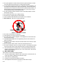
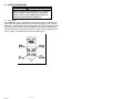
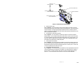
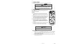
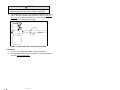
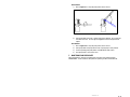
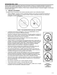
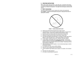
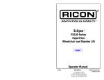
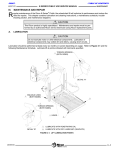
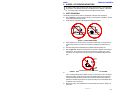
-PRINT- -TABLE OF CONTENTS® II. K-SERIES LIFT OPERATING INSTRUCTIONS T A. his chapter contains safety precautions, daily safety check instructions, control and indicator descriptions, and operating instructions for the RICON K-Series® KlearVue™ Wheelchair Lift. This chapter must be thoroughly understood by operator before using lift. SAFETY PRECAUTIONS The following safety precautions must be complied with at all times when operating lift: Refer to Figure 2-1. Deploying lift when vehicle is on sloped ground is hazardous. Operate lift with vehicle parked on level ground. Vehicle must be safely parked with parking brake ON before using lift. FIGURE 2-1: SLOPED PARKING HAZARD Inspect lift before use. DO NOT use lift if any unsafe condition exists, or unusual noises or movements are noticed, and contact a Ricon dealer or qualified service technician for repair. Read and comply with all warning labels and symbols affixed to wheelchair lift. Refer to Figure 2-2. Wheelchair occupant must face outward on platform when entering or exiting vehicle. Due to variations in the size and configuration of mobility aids, for maximum safety, Ricon requires that passengers always face outward when riding the lift platform. FIGURE 2-2: ALWAYS FACE OUTBOARD WHEN RIDING ON THE LIFT PLATFORM It is never safe for a wheelchair occupant to exit a vehicle facing inboard. It is not safe to rely on a threshold warning device (audible or other) to confirm that it is safe to exit vehicle while facing inboard. Exiting the vehicle while facing outboard allows for visual confirmation that the lift platform has been raised in the event that the threshold warning device is inoperative or unheard and prevents the occupant from exiting the vehicle backwards when the platform is still on the ground. When exiting vehicle, verify that platform is at same height as floor and front rollstop is up and locked. 32DSS101.D 2-1 Do not place equipment or furniture inside vehicle that may prevent pivoting of your wheelchair. Being able to pivot assures that you can safely exit facing outward. The outer rollstop is intended to prevent slow, or unintentional, rolling off the platform. The outer rollstop is not designed to stop a quick moving wheelchair. The wheelchair might tip and possibly injure its occupant if the small front wheels collide hard with the rollstop. The large rear wheels of a quick moving wheelchair can also roll over the rollstop. Use great care, board platform slowly, and lock wheelchair brakes. Be certain wheelchair fits safely on platform; it must not extend beyond edges or interfere with operation of rollstop. Do not operate with a load in excess of 800 lbs (364 kg). Keep arms, legs, and clothing away from moving lift parts. The lift is intended for ONE wheelchair and its occupant. Do not overload lift. Refer to Figure 2-3. Keep others clear while operating lift. FIGURE 2-3: STAND CLEAR OF PLATFORM Do not allow an untrained person to operate lift. Careful supervision is necessary if used by or near children. Do not allow anyone to stand on bridgeplate. A bent bridgeplate can interfere with the platform as it raises and lowers. LOCK WHEELCHAIR BRAKES before moving platform (power chair users should turn off power and set brake). Use great care in wet conditions, because the wheelchair brakes are less effective if wheels or platform are wet. Never leave platform outside of vehicle. Return lift to stowed position after use. Do not place a wheelchair on lift if it is too large for the vehicle. The wheelchair must be able to pivot freely inside vehicle to comply with lift instructions for entering and exiting vehicle. Read and understand these safety precautions. Review them periodically and ask any attendants or other operators to read them as well. Contact a Ricon dealer or Ricon Product Support if there are questions. B. DAILY SAFETY CHECK Inspect lift before use and meet the following conditions: All functions operate properly. DO NOT use lift if unusual noises or movements exist, and contact a Ricon dealer or qualified service technician for repair. Vehicle interlock is operating properly. No objects that may interfere with operation are present. General appearance and lubrication are satisfactory and all fasteners are tight. 2-2 32DSS101.D C. LIFT FUNCTIONS TABLE 2-1: LIFT FUNCTIONS FUNCTION DESCRIPTION DEPLOY Platform unfolds and deploys from stowed position. (the doors will automatically open before lift deploys if vehicle is equipped with a power door operator). DOWN Platform lowers from floor level to ground level. (rollstop lowers automatically when platform contacts ground). UP Platform raises from ground level to floor level. (rollstop raises automatically when platform leaves ground). STOW Platform folds and stows from floor level. (the doors will automatically close after lift is stowed if vehicle is equipped with a power door operator). END OF TABLE NOTE: The up and down functions do not operate when platform is stowed. NOTE: ARMRESTS AND PINCH POINT SHIELDS REMOVED FOR CLARITY. STOWED POSITION VEHICLE FLOOR LEVEL GROUND LEVEL FIGURE 2-4: PLATFORM POSITIONS 32DSS101.D 2-3 D. CONTROLS AND INDICATORS WARNING THE LIFT CAN OPERATE ONLY WHEN PERMITTED TO BY THE VEHICLE INTERLOCK CIRCUITRY. DO NOT OPERATE LIFT WITH INTERLOCK BYPASSED. REFER TO VEHICLE OWNER/OPERATOR MANUAL FOR INTERLOCK INSTRUCTIONS BEFORE OPERATING LIFT. Control Pendant Refer to Figure 2-5. The lift is operated with two rocker buttons located on a hand-held, hardwired remote-control pendant. Each lift function is controlled by pushing one end of the appropriate button. Pushing the DEPLOY button unfolds platform from vehicle, and pushing the STOW button folds platform into vehicle. Pushing the DOWN button lowers platform towards ground, and pushing the UP button raises platform towards floor. Buttons must be held depressed until function completes. The pendant is stowed on a wall-clip inside vehicle. FIGURE 2-5: LIFT CONTROL PENDANT 2-4 32DSS101.D INTERLOCK INDICATOR LIGHT OR LED STATUS INDICATOR 30 AMP DOOR OPERATOR CIRCUIT BREAKER PUMP SOLENOIDS 8 AMP CONTROL SYSTEM CIRCUIT BREAKER FIGURE 2-6: INDICATOR LIGHT/ CIRCUIT BREAKERS Interlock Indicator Light Refer to Figure 2-6. The vehicle interlock system prevents operation of lift when it is unsafe. The interlock indicator light reveals whether interlock is operating properly, if an interlock system is interfaced with lift. The light stays illuminated at all times if there is no interlock system installed. The indicator light illuminates when the interlock system provides electrical power to lift, and is off when power is removed. Circuit Breaker for Optional Door Operator Refer to Figure 2-6. The circuit breaker for optional door operator is mounted on hydraulic pump assembly. The circuit breaker button pops up when there is a short circuit in door operator. DO NOT hold button pressed if pressing and releasing button does not restore power. Contact a Ricon dealer or qualified service technician for repair. Refer to appropriate Ricon Power Door Operator Service Manual for a detailed description. Control System Circuit Breaker Refer to Figure 2-6. The Control System Circuit Breaker is mounted on hydraulic pump assembly. The circuit breaker button pops up when there is a short circuit in the control system. DO NOT hold button pressed if pressing and releasing button does not restore power. Contact a Ricon dealer or qualified service technician for repair. Pump Solenoid LED Status Indicator Refer to Figure 2-6. A second pump solenoid is installed next to the original pump solenoid and a LED is located between the 8A and 30A circuit breakers. The LED monitors the condition of the two solenoids. The LED is normally green when the pump is operating and off when the pump is off. For more information on this LED refer to the service manual 32DSSP02. 32DSS101.D 2-5 Main Circuit Breaker Refer to Figure 2-7. The main circuit breaker, located in engine compartment, interrupts electrical power to the lift electrical system when a short circuit occurs. The circuit breaker reset tab is shown in the normal, or reset, position. The circuit breaker reset tab flips down when a short circuit occurs. DO NOT hold button pressed if pressing and releasing button does not restore power. Contact a Ricon dealer or qualified service technician for repair. FIGURE 2-7: MAIN CIRCUIT BREAKER Manual Backup Pump Refer to Figure 2-8. The manual backup pump raises the platform when electrical power is not functional. Controls for the pump consist of a handle for raising platform, and a release valve for lowering it. Instructions for operating the manual pump are in the MANUAL OPERATION paragraph of the LIFT OPERATION section in this chapter. FIGURE 2-8: MANUAL BACKUP PUMP & HANDLE 2-6 32DSS101.D E. LIFT OPERATION WARNING IMPROPER USE OF LIFT CAN RESULT IN PERSONAL INJURY. USERS MUST READ AND FOLLOW OPERATING INSTRUCTIONS IN OPERATOR MANUAL. ADDITIONAL COPIES OF OPERATOR MANUAL ARE AVAILABLE FROM: RICON CORPORATION 7900 NELSON ROAD PANORAMA CITY, CA 91402 (800) 322-2884 OR (818) 267-3000 DO NOT EXCEED RATED LOAD CAPACITY OF 800 POUNDS (364 KG). PRIOR TO USE, INSPECT WHEELCHAIR LIFT FOR PROPER FUNCTION, REQUIRED MAINTENANCE, AND DAMAGE. IF A PROBLEM EXISTS, DO NOT USE LIFT AND CONTACT A RICON DEALER OR QUALIFIED SERVICE TECHNICIAN FOR REPAIR. THIS LIFT IS DESIGNED FOR USE BY WHEELCHAIR OCCUPANTS ONLY. RICON CORPORATION DISCLAIMS LIABILITY FOR DAMAGE OR PERSONAL INJURY RESULTING FROM MODIFICATION TO LIFT, LACK OF MAINTENANCE OR REPAIR, NEGLIGENCE, ABUSE, OR FAILURE TO FOLLOW LIFT OPERATING INSTRUCTIONS. Be certain vehicle is safely parked on a level area away from traffic before operating lift. Allow space for lift operation and passenger boarding. The lift operator must take special care to be certain that area is clear before deploying lift. Be certain there are no obstacles beneath platform. Open doors manually if vehicle is not equipped with a Power Door Operator. The vehicle door(s) will open automatically before platform deploys and close after platform is stowed, if vehicle is equipped with a Power Door Operator. Engage the vehicle safety interlock system (e.g. transmission, parking brake, etc), if so equipped, before operating lift. The lift will not operate until this is accomplished. WARNING ATTENDANT SHOULD ALWAYS REMAIN NEAR PASSENGER TO RENDER IMMEDIATE ASSISTANCE, IF NECESSARY. KEEP OTHERS CLEAR WHEN OPERATING LIFT. MAINTAIN PRESSURE ON BUTTON UNTIL FUNCTION COMPLETES. BE CERTAIN WHEELCHAIR FITS PROPERLY ON PLATFORM AND DOES NOT CONTACT ROLLSTOP, PREVENTING IT FROM LOCKING AS PLATFORM RAISES. 32DSS101.D 2-7 1. ENTERING VEHICLE: a. DEPLOY PLATFORM - Push and hold DEPLOY button until platform unfolds completely from vehicle and stops at floor level. WARNING DO NOT STAND ON BRIDGEPLATE (INBOARD ROLLSTOP) AS PLATFORM LOWERS. PUSH AND HOLD DOWN BUTTON UNTIL PLATFORM SETTLES AT GROUND LEVEL. CAREFULLY EXIT PLATFORM. b. c. d. 2. LOWER PLATFORM - DO NOT STAND on inboard rollstop as platform lowers. Push and hold DOWN switch until lift contacts ground and rollstop opens completely. 1) Carefully place wheelchair in center of platform, facing outward away from vehicle, and LOCK WHEELCHAIR BRAKES. 2) Be certain wheelchair is safely within platform perimeter and will not interfere with operation of front platform rollstop. RAISE PLATFORM - Push and hold UP button until platform raises and stops at vehicle floor level. Rollstop must raise when platform leaves ground. 1) Release wheelchair brakes, carefully board passenger into vehicle, and secure wheelchair. Refer to “Stowing Platform” section to stow platform. EXITING VEHICLE: a. b. c. DEPLOY PLATFORM - Push and hold DEPLOY button until platform completely unfolds from vehicle and stops at floor level. 1) Be certain platform is safely at vehicle floor level, front platform rollstop is in an up and locked position and bridgeplate is resting on baseplate. 2) Carefully place wheelchair in center of platform, facing outward away from vehicle, and LOCK WHEELCHAIR BRAKES. LOWER PLATFORM – DO NOT STAND on inboard rollstop as platform lowers. Push and hold DOWN button until platform settles at ground level. Carefully exit platform. RAISE PLATFORM – Push and hold UP switch until platform rises to vehicle floor level. WARNING DO NOT STAND ON BRIDGEPLATE (INBOARD ROLLSTOP) AS PLATFORM LOWERS. 2-8 32DSS101.D 3. y STOWING PLATFORM: Push and hold STOW button until platform is completely within vehicle. CAUTION Do not release stow button before platform is folded completely and pump motor stops operating. Be certain platform is stowed completely before closing doors. 4. MANUAL OPERATION: Refer to Figure 2-9. The lift can be operated manually if lift electrical power is not functional. Preparation: y y y y y Be certain vehicle is on a level area and away from traffic. Allow enough space for lift operation and passenger boarding. The operator must summon emergency assistance to move vehicle to a safe operating area if a break down situation exists and vehicle cannot be moved under its own power. Check to be certain obstacles are not in path of lift. Open door(s) manually if vehicle is not equipped with a Power Door Operator. If equipped with a Power Door Operator, refer to its Operator Manual for manual operation instructions. Consider that vehicle beeper may not be operating, and caution people in vicinity that platform is about to deploy. FIGURE 2-9: MANUAL OPERATION WARNING FOLLOW PRECAUTIONS IN “LIFT OPERATION” SECTION WHEN USING MANUAL BACKUP SYSTEM TO ENTER OR EXIT VEHICLE. Deploy Platform 1) 2) Release "Sto-Loc" by lifting bridgeplate (inboard rollstop). If "Sto-Loc" is difficult to release, use manual backup pump to remove tension from catch; refer to “Stow Platform” paragraph in this section. Insert notched end of pump handle through “RELEASE VALVE” hole in pump cover, and engage pump release valve. 32DSS101.D 2-9 CAUTION Do not open pump release valve more than ¼-turn. Opening valve further may cause it to completely disengage from pump body, which will disable its pumping ability. 3) Refer to Figure 2-10. Turn valve 1/4 turn COUNTER-CLOCKWISE to begin lowering platform. Turn valve CLOCKWISE when platform reaches floor level; do not overtighten valve. Do not lower platform below level. The rear edge of bridgeplate (inboard rollstop) must rest flat against lift baseplate. FIGURE 2-10: MANUAL BACK-UP PUMP - DEPLOY AND LOWER PLATFORM Lower Platform 1) 2) 2 - 10 Turn valve 1/4 turn COUNTER-CLOCKWISE to begin lowering platform. Hold valve OPEN until platform settles at ground level. Turn handle CLOCKWISE to close valve; do not over-tighten valve. 32DSS101.D Raise Platform 1) Refer to Figure 2-11. Verify that pump release valve is closed. FIGURE 2-11: MANUAL BACK-UP PUMP – RAISE PLATFORM 2) Insert pump handle into socket. Operate pump to raise platform. Do not raise platform above floor level. The rear edge of bridgeplate must rest flat against lift baseplate. Stow Platform 1) 2) 3) 4) F. Refer to Figure 2-10. Verify that pump release valve is closed. Insert pump handle into pump handle socket. Operate pump to raise platform. Continue operating pump until platform is COMPLETELY within vehicle. Stow pump handle. Close vehicle doors. MAINTENANCE AND REPAIR NOTE Follow the lubrication, cleaning, and maintenance instructions in the following chapter, MAINTENANCE. These instructions will optimize the operating condition of wheelchair lift. 32DSS101.D 2 - 11 This page intentionally left blank. -BACK TO TOP2 - 12 -GO TO NEXT CHAPTER32DSS101.D