1
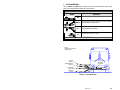
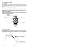
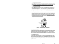
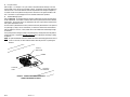
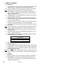
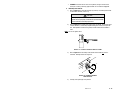
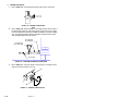
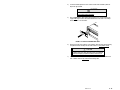
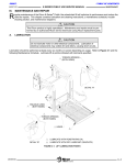
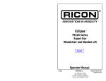
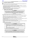
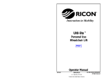
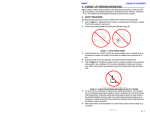
II. OPERATING INSTRUCTIONS
T
his chapter contains safety precautions, a daily safety check, a description of lift functions,
control and indicator descriptions, plus individual operating instructions for the Ricon Mirage
F9TF Public Use wheelchair and standee lift. This chapter must be thoroughly understood by the
operator.
A. SAFETY PRECAUTIONS
The following safety precautions must be complied with at all times when operating lift:
Refer to Figure 2-1. Operate lift with vehicle parked on level ground. Deploying lift when vehicle is on
sloped ground is hazardous.
FIGURE 2-1: VEHICLE INCLINED DUE TO SLOPE
Vehicle must be safely parked with parking brake on before using lift.
Inspect lift before use. Do not use lift if an unsafe condition exists, or if unusual noise or
movement is noticed. Contact a Ricon authorized service technician for repair.
Read and comply with all warning labels and symbols affixed to wheelchair lift.
Wheelchair occupant should face outward when entering or exiting vehicle.
Do not back onto platform when exiting vehicle. Face outward, if possible, and verify that
platform is at the same height as floor. Check that front rollstop is up and locked.
The front rollstop is intended to prevent slow, unintentional, rolling off of platform.
The front rollstop is not intended to stop a quick moving wheelchair. A quick moving
wheelchair could tip if the small front wheels collide with the rollstop. Also, the large rear
wheels of a quick moving wheelchair could roll over the rollstop. Possible injury to the occupant might occur in either case.
Verify that wheelchair fits safely on platform; it must not extend beyond edges or interfere
with operation of rollstop.
Do not operate with a load in excess of 660 lbs (300 kg).
Keep arms, legs, and clothing away from moving lift parts.
The lift is intended for one wheelchair and its occupant, or one standee. Do not overload
lift.
Keep others clear while operating lift.
Do not allow an untrained person to operate lift.
32DF9T15.A
2-1
Do not allow anyone to stand on bridgeplate. A bent bridgeplate can interfere with the platform as it raises and lowers.
Lock wheelchair brakes before raising or lowering platform (power chair users should turn
off power and set brake).
Use great care in wet conditions; the wheelchair brakes are less effective if its tires or the
platform are wet.
Do not leave deployed platform unattended. Return to stowed position after use.
Read and understand the preceding safety precautions. Review them periodically and ask attendants or
other operators to read them as well. Contact a Ricon authorized service technician or call Ricon Product
Support if there are questions.
B.
PRE-OPERATION LIFT INSPECTION
Refer to the “Driver Checklist” section in Chapter 3. Ricon recommends that the listed inspection points be performed each time the vehicle is put into service, or when a driver change occurs during a work-shift. This inspection can be part of the normal pre-use walk-through done
by the vehicle operator.
2-2
32DF9T15.A
C. PLATFORM MOTIONS
Refer to Table 2-1 and Figure 2-2. The table describes the four platform motions, and the figure
shows the four typical platform heights plus the stow position.
TABLE 2-1: PLATFORM MOTIONS
MOTION
DESCRIPTION
OUT
Platform extends out of vehicle, or deploys.
Platform lowers from present height towards ground; front rollstop
DOWN * lowers when platform contacts ground.
UP *
IN
Platform rises from present height towards vehicle floor; rollstop
rises before platform leaves ground.
Platform retracts into vehicle, or stows.
END OF TABLE
*
The UP and DOWN motions operate only when platform is fully deployed.
NOTE:
HANDRAILS OMITTED
FOR CLARITY.
FLOOR
HEIGHT
STOWED
POSITION
INTERMEDIATE
HEIGHT
DEPLOYED
POSITION
GROUND
LEVEL
FIGURE 2-2: PLATFORM POSITIONS
32DF9T15.A
2-3
D. CONTROLS AND INDICATORS
Control Pendant
Refer to Figure 2-3. The lift is operated with a hand-held, hard-wired remote-control pendant.
Turn on the POWER ENABLE switch and then control each lift motion by pressing an appropriate
button.
The POWER ENABLE switch provides power to the pendant and thereby enables the lift. When
turned on, the power switch and each button illuminate.
Pressing the DEPLOY button extends the platform from the lift storage compartment, and pressing the STOW button retracts the platform back into the storage compartment. Pressing the
DOWN button lowers the platform towards the ground, and pressing the UP button raises the
platform towards the vehicle floor.
A button must be held depressed until the motion is completed. Movement of the platform can
be halted at any time by releasing the button.
POWER
ENABLE
POWER
OFF
ON
STOW
DEPLOY
DEPLOY
STOW
UP
DOWN
UP
DOWN
FIGURE 2-3: CONTROL PENDANT
Electric Circuit Breakers
Refer to Figure 2-4. The circuit breakers shown interrupt electric power to specific sections of
the lift if a malfunction causes an abnormally high current flow. The Control System and In/Out
Motor circuit breakers are mounted on a common bracket, which is located at the top of the hydraulic pump enclosure.
IN/OUT MOTOR
CIRCUIT BREAKER
CONTROL SYSTEM
CIRCUIT BREAKER
2-4
FIGURE 2-4: LIFT CIRCUIT BREAKERS
32DF9T15.A
Control System Circuit Breaker
Refer to Figure 2-4. The five-amp control system circuit breaker is in the pump box. The circuit breaker button will “pop-out” when a control system short circuit occurs. Press button to
reset. Do not press button and hold it if pressing and releasing does not restore power. Contact a Ricon authorized service technician for repair.
In/Out Motor Circuit Breaker
Refer to Figure 2-4. The 30 amp In/Out motor circuit breaker is also in the pump box. The
circuit breaker button will “pop-out” when a short circuit occurs in the motor circuit that extends and retracts the platform. Press button to reset. Do not press button and hold it if
pressing and releasing does not restore power. Contact a Ricon authorized service technician
for repair.
Main Lift Circuit Breaker
Refer to Figure 2-5. The main circuit breaker is mounted in the vehicle engine or battery compartments, and will interrupt electrical power if a major short circuit occurs, particularly in the
hydraulic pump motor circuit. The reset tab rotates clockwise when a short occurs. Rotate
the reset tab counter-clockwise to reset breaker (as shown). Do not rotate tab and hold it if
rotating and releasing does not restore power. Contact a Ricon authorized service technician
for repair.
RESET
TAB
FIGURE 2-5: MAIN CIRCUIT BREAKER – SHOWN RESET
Vehicle Interlock System
The purpose of the vehicle interlock system is to prevent lift operation if it is unsafe to do so.
Typical requirements are that the vehicle transmission be in neutral, the parking brake be applied,
and the passenger door be opened before power is supplied to the lift. Before the vehicle can
depart, the lift must be stowed, and both the lift compartment door and passenger door must be
closed.
Bridgeplate Load Sensor
A sensor switch is located in the hydraulic line connected to the bridgeplate hydraulic cylinder.
When the sensor detects that an object is present on the bridgeplate it inhibits raising or lowering
of the platform. This protects the passenger from possible injury when the cylinder raises the
bridgeplate. It also protects the bridgeplate from damage, which could interfere later with proper
operation of the lift.
32DF9T15.A
2-5
Lift Cycle Counter
Refer to Figure 1-1 in Chapter I. The cycle counter is mounted inside the carriage, on the rear
frame member, just to the right of the hydraulic cylinder. The platform must be fully deployed to
view the counter. The counter advances each time the platform moves through a complete cycle, which consists of the platform moving from the vehicle floor to the ground and back to the
floor. The number of cycles displayed is used to schedule maintenance operations.
Threshold Warning System
Refer to Figure 2-6. The threshold warning system is installed at the top of the doorway above
the lift compartment. The module is turned on when the lift is powered, and the status indicator
will then light. The acoustic sensors are enabled when the door is open and the lift-vehicle interlock system requirements are met.
Acoustic sensors (transmitter and receiver) monitor the doorway threshold area for the presence
of a passenger (or object, such as a wheelchair). If someone is detected in the threshold area
when the platform is one inch, or more, below the floor an audible buzzer and flashing red light
are actuated.
This system provides a margin of safety for lift passengers by warning them when the platform
is below floor level. The platform must be at floor level when a passenger is boarding or exiting
the platform.
NOTE: An optional installation method can disable the buzzer and flashing light when the door is
closed. In this case, the status indicator flashes when the presence of a passenger is
detected.
STATUS
INDICATOR
BUZZER
FLASHING
LIGHT
ACOUSTIC
SENSORS
FIGURE 2-6: THRESHOLD WARNING SYSTEM MODULE
(VIEWED FROM INTERIOR OF VEHICLE)
2-6
32DF9T15.A
E.
LIFT OPERATION
WARNING
IMPROPER USE OF LIFT CAN RESULT IN PERSONAL INJURY. USERS MUST READ AND FOLLOW OPERATING INSTRUCTIONS IN THIS MANUAL. ADDITIONAL COPIES OF THE OPERATOR MANUAL ARE AVAILABLE FROM:
RICON CORPORATION
7900 NELSON ROAD
PANORAMA CITY, CA 91402
(818) 267-3000 or (800) 322-2884
DO NOT EXCEED RATED LOAD CAPACITY OF 660 POUNDS (300 KG).
INSPECT WHEELCHAIR LIFT FOR PROPER FUNCTION, REQUIRED MAINTENANCE, AND DAMAGE
PRIOR TO USE. DO NOT USE LIFT IF A PROBLEM EXISTS, AND CONTACT AN AUTHORIZED RICON
SERVICE TECHNICIAN FOR REPAIR.
THIS LIFT IS TO BE USED BY ONE WHEELCHAIR OCCUPANT OR ONE STANDEE, ONLY.
RICON CORPORATION DISCLAIMS LIABILITY FOR DAMAGE OR PERSONAL INJURY RESULTING FROM MODIFICATION TO THE LIFT, LACK OF MAINTENANCE OR REPAIR, NEGLIGENCE, ABUSE, OR FAILURE TO FOLLOW THE OPERATING INSTRUCTIONS.
Before operating lift, be certain vehicle is safely parked on a level area away from traffic.
Provide space for lift operation and passenger boarding.
The lift operator must take special care to ensure that area is clear before deploying platform. Be certain there are no obstacles beneath platform.
Open lift compartment doors completely and secure.
Open passenger entry door directly above lift compartment. This does not apply to models
that stop upward platform movement prior to reaching floor level. The entry door on these
models is opened after the platform reaches intermediate height (refer to Figure 2-2).
If the vehicle and lift are equipped with a safety interlock system (e.g. transmission, parking
brake, etc) be certain that it is in the proper mode before attempting to operate lift. The lift
will not operate until this feature has been properly engaged.
Turn on lift power switch located on or near vehicle dashboard, if so equipped.
Enable lift control pendant by turning on Power switch located on pendant.
A person that uses the wheelchair lift while standing (does not require mobility aid equipment) is referred to in this manual as a Standee.
WARNING
THE ATTENDANT MUST REMAIN NEAR LIFT PASSENGER
TO PROVIDE ASSISTANCE, IF NECESSARY.
WARNING
THE LIFT CAN ONLY BE OPERATED WHEN ENABLED BY THE VEHICLE INTERLOCK
CIRCUITRY. DO NOT BYPASS THE INTERLOCK TO OPERATE LIFT. REFER TO VEHICLE
SERVICE MANUAL FOR INTERLOCK INFORMATION BEFORE OPERATING LIFT.
WARNING
CAUTION PASSENGERS TO STAY CLEAR OF PASSENGER ENTRY DOOR WHILE IT IS OPENED.
32DF9T15.A
2-7
1.
NORMAL LIFT OPERATION
a.
To Enter Vehicle:
1)
ACTIVATE INTERLOCK: Refer to vehicle manufacturers operator manual to enable
vehicle interlocks; i.e. set parking brake, place transmission in neutral, etc.
2) DEPLOY PLATFORM: Press and hold OUT button until platform is fully deployed.
NOTE: Platform cannot be moved up or down unless platform is fully extended.
3) RAISE HANDRAILS: Lift right handrail to vertical and push firmly down into its
socket. Repeat for left handrail. Verify that both handrails are latched in place by
attempting to pull upward on them.
4) LOWER PLATFORM: Press and hold DOWN button until platform stops at ground
level and rollstop opens completely.
5) BOARD PLATFORM: Position wheelchair in center of platform, facing outward if
possible, and advise occupant to lock wheelchair brakes. Power should be turned
off on electric-powered wheelchairs.
Standee must stand near the center of the platform, facing in the direction of travel
(into vehicle), and firmly grasp handrails. Do not stand on bridgeplate.
6) BUCKLE SAFETY BELT. Pull safety belt from retractor on left handrail and fasten to
other handrail.
NOTE: The next two steps apply only to F9TF models that stop upward platform movement
at an intermediate level (refer to Figure 2-2). Other models continue at step 9.
7) PARTIALLY RAISE PLATFORM: Press and hold UP button until platform stops at
intermediate height.
8) OPEN VEHICLE DOOR: Fully open vehicle sliding door located above lift. The lift
operator, or attendant should do this.
9) RAISE PLATFORM: Press and hold UP button until platform stops at floor height
and bridgeplate lowers onto vehicle floor.
CAUTION
Verify that rear edge of bridgeplate lies flat on floor along
its entire edge and does not create a tripping hazard.
10) EXIT PLATFORM: Advise passenger to carefully enter vehicle.
11) UNBUCKLE SAFETY BELT.
12) LOWER HANDRAILS: Press release button at base of handrail and lift the left handrail upward out of its socket. Lower handrail to platform. Repeat for right handrail.
13) STOW PLATFORM: Press and hold IN button until platform reaches STOW height
and then fully retracts into vehicle.
NOTE: Do not use DOWN button to lower platform partway prior to stowing, and then complete the stowing process by using IN button. This method may not properly stow
platform.
b.
To Exit Vehicle:
1)
2)
2-8
DEPLOY PLATFORM: Press and hold OUT button until platform is fully deployed.
RAISE HANDRAILS: Lift right handrail to vertical and push firmly down into its
socket. Repeat for left handrail. Verify that both handrails are latched in place by
attempting to pull upward on them.
32DF9T15.A
3)
BUCKLE SAFETY BELT. Pull safety belt from retractor on left handrail and fasten to
other handrail.
NOTE: The next two steps apply only to F9TF models that stop upward platform movement
at an intermediate level (refer to Figure 2-2). Other models continue at step 6.
4) PARTIALLY RAISE PLATFORM: Press and hold UP button until platform stops at
intermediate height.
5) OPEN VEHICLE DOOR: Fully open vehicle sliding door located above lift. The lift
operator, or attendant should do this.
6) RAISE PLATFORM: Press and hold UP button until platform stops at floor height
and bridgeplate lowers onto vehicle floor.
CAUTION
Verify that rear edge of bridgeplate lies flat on floor along
its entire edge and does not create a tripping hazard.
7)
BOARD PLATFORM: Position wheelchair in center of platform, facing outward if
possible, and advise occupant to lock wheelchair brakes. Power should be turned
off on electric-powered wheelchairs.
Standee must stand near the center of the platform, facing in the direction of travel
(out of vehicle), and firmly grasp handrails. Do not stand on bridgeplate.
8) LOWER PLATFORM: Press and hold DOWN button until platform stops at ground
level and rollstop opens completely.
9) UNBUCKLE SAFETY BELT.
10) EXIT PLATFORM: Carefully assist passenger off of platform.
11) LOWER HANDRAILS: Press release button at base of handrail and lift the left handrail upward out of its socket. Lower handrail to platform. Repeat for right handrail.
12) STOW PLATFORM: Press and hold IN button until platform reaches STOW height
and then fully retracts into vehicle.
32DF9T15.A
2-9
2.
MANUAL LIFT OPERATION
The lift can be operated manually if it loses electrical power. The following sections describe
the lift controls associated with manual operation, important safety preparations to be followed
before using the lift, and operating procedures to deploy, raise, lower, and stow the lift. Ricon
recommends that manual operation be used only to exit from vehicle, not to enter vehicle.
a.
Manual Lift Controls
Manual operation components used are a hydraulic backup pump, platform release mechanism, and a rollstop control knob.
Hydraulic Backup Pump
Refer to Figure 2-7. The manual back -up pump is part of the hydraulic pump assembly,
and is operated with a separate pump handle. Pumping the handle raises the platform
when the release valve is closed. A pump pressure release valve for bleeding pressure
from the hydraulic system is also on the hydraulic pump assembly and is rotated with the
pump handle. Opening the release valve lowers platform.
The handle is also used to rotate the platform release shafts. Note that handle can be unfolded to gain greater leverage when rotating release shafts.
BACKUP
PUMP
SOCKET
PUMP
RELEASE
VALVE
PUMP
HANDLE
FIGURE 2-7: MANUAL BACKUP PUMP & HANDLE
Platform Release Shafts
Refer to Figure 2-8. The stowed platform is difficult to withdraw against the resistance of
the deployment system. For that reason, a release mechanism is provided to disengage the
platform when manual deployment is necessary. The platform is released by rotating either
keyed release shaft in the direction shown on the adjacent decal. The shafts are located
behind cutouts at the left and right sides of the front rollstop.
KEYED RELEASE
SHAFTS
ROT
STE ATE
90 M
CW
UNL TO
PLATOCK
FOR
MANUAL PUMP
HANDLE
ROT
ATE
STEM
90
CW
UNL TO
PLATOCK
FOR
M
DECAL
2 - 10
FIGURE 2-8: PLATFORM RELEASE SHAFTS
32DF9T15.A
Rollstop Control Knob
Refer to Figure 2-9. The manual rollstop control knob operates the platform rollstop directly. It is located on the right side of the platform. Lower platform to ground before attempting to lower, or open, the rollstop. Pull the control knob out and turn it counterclockwise to lower the rollstop. Close, or raise, the rollstop by pulling the control knob out
and turning it clockwise. Sometimes, closing the rollstop is easier if you lift the rollstop
with one hand, while turning the knob with the other hand.
CONTROL
KNOB
FIGURE 2-9: MANUAL ROLLSTOP CONTROL KNOB
Preparation:
Park vehicle on a level surface, away from traffic. Allow sufficient space for lift operation and passenger boarding.
The operator must summon assistance to move vehicle to a safe operating area if a
breakdown situation exists and vehicle cannot be moved under its own power.
Check to be certain obstacles are not in path of platform movement.
Open vehicle doors by hand and secure.
Caution people in vicinity that platform is about to deploy.
Follow the Safety Precautions at the beginning of this chapter when a passenger enters or exits the platform.
Manually Deploy Platform:
b.
1)
Refer to Figure 2-10. Obtain manual pump handle from its storage location, unfold, and engage either keyed release shaft located behind access holes in rollstop.
Rotate the shaft ¼ turn clockwise.
FIGURE 2-10: ROTATE PLATFORM RELEASE SHAFT
32DF9T15.A
2 - 11
WARNING
AN ABLE-BODIED PERSON MUST DEPLOY THE PLATFORM.
USE CAUTION AND AVOID INJURY.
2)
Grasp the top edge of the front rollstop with two hands and pull firmly. The platform moves smoothly after an initial resistance. Pull platform straight out to the
end of its travel.
3) Lift right handrail to vertical and push firmly down into its socket. Repeat for left
handrail
c. Manually Raise Platform:
1)
Refer to Figure 2-11. Engage pump release valve with pump handle. Note that the
notches in handle must engage the pin on the stem of the release valve. Turn valve
lightly clockwise to verify that valve is closed (valve should have been closed previously). Remove handle.
FIGURE 2-11: CLOCKWISE CLOSES RELEASE VALVE
2)
Refer to Figure 2-12. Verify that rollstop is up (closed). Pull rollstop control knob
out and rotate fully clockwise, if it isn’t up.
FIGURE 2-12: CLOCKWISE CLOSES ROLLSTOP
3)
4)
2 - 12
Refer back to Figure 2-11. Insert handle into backup pump socket, then pump
handle to raise platform to floor height.
Position wheelchair in center of platform, facing outward if possible, and advise occupant to lock wheelchair brakes. Power should be turned off on electric-powered
wheelchairs.
32DF9T15.A
STANDEE must stand near the center of the platform, facing in the direction of
travel (out of vehicle), and firmly grasp handrails. Do not stand on bridgeplate.
Manually Lower Platform:
d.
1)
Refer to Figure 2-12. Verify that rollstop is up (closed). Pull rollstop control knob
out and rotate clockwise, if it isn’t up.
CAUTION
Do not open pump release valve more than 1/4-turn. The valve will
separate from the pump body if unthreaded too far, which will disable
both the automatic and manual pump functions.
2)
Refer to Figure 2-13. Engage pump release valve with handle. Slowly rotate valve
counter-clockwise (1/4-turn max) until platform begins to lower; do not open further. Allow platform to settle on the ground, and then rotate valve clockwise to
close.
NOTE: Do not over-tighten valve!
FIGURE 2-13: COUNTER-CLOCKWISE LOWERS PLATFORM
3)
Refer to Figure 2-14. Pull rollstop control knob out and rotate fully counterclockwise. Rollstop must lie flat on ground.
FIGURE 2-14: COUNTER-CLOCKWISE
OPENS ROLLSTOP
4)
Carefully assist passenger off of platform.
32DF9T15.A
2 - 13
e.
Manually Stow Platform:
1)
2)
Refer to Figure 2-15. Verify that pump pressure release valve is closed (CW).
FIGURE 2-15: CLOCKWISE CLOSES RELEASE
VALVE
Refer to Figure 2-16. Raise the platform to stow height; position the top surface of
the platform lifting frame arm at the same height as the top surface of the carriage.
If the exact height cannot be obtained, a slightly low platform is preferred to slightly
high. This alignment eliminates interference between the platform and enclosure
when pushing the platform into the enclosure.
TOP SURFACE
OF CARRIAGE
TOP SURFACE
OF LIFTING ARM
PLATFORM
FIGURE 2-16: LIFTING ARM AND CARRIAGE AT SAME HEIGHT
3)
Refer to Figure 2-17. Verify that rollstop is closed (fully up). Pull rollstop control
knob out and rotate clockwise, if it isn’t up.
FIGURE 2-17: CLOCKWISE CLOSES ROLLSTOP
2 - 14
32DF9T15.A
4)
Lift the left handrail upward out of its socket and then lower handrail to platform.
Repeat for right handrail.
WARNING
AN ABLE-BODIED PERSON MUST STOW THE PLATFORM.
USE CAUTION AND AVOID INJURY.
5)
Refer to Figure 2-18. Obtain manual pump handle from its storage location and
engage either keyed release shaft located behind the access holes in the rollstop.
Rotate the shaft ¼ turn clockwise.
FIGURE 2-18: ROTATE PLATFORM RELEASE SHAFT
6)
Grasp the top edge of the rollstop, or the handrails, with two hands and push firmly.
The platform moves smoothly after an initial resistance. Push platform in fully.
CAUTION
The platform must lock in place when fully stowed. Check platform
retention by attempting to pull platform outward; it must not move.
7)
If platform does not lock, rotate either platform release shaft ¼ turn counterclockwise. Platform must be fully stowed before rotating shaft.
32DF9T15.A
2 - 15
-RETURN TO TABLE OF CONTENTS-
-GO TO NEXT CHAPTER-
This page intentionally left blank.
2 - 16
32DF9T15.A