1
22,5"
OPERATOR
MANUAL
Initial issue : 05/11
Latest revision : 05/12
9.134.244
Content of this documentation has a confidential nature and remains
the exclusive property of c.p. bourg s.a. It is only put at the user
(including without limitation: Renter or Purchaser or their employees)
disposal within the exclusive scope of using and servicing the product.
Without c.p. bourg s.a. prior agreement in writing, disclosure to
third party and/or reproductions as well as changes are prohibited.
Operator Manual Initial issue: 05/11
Page 9 - 2
Latest revision: 10/11/11
22,5"
Table of content
1. Introduction5
1.1 Foreword............................................................................................................ 5
1.2 Warning pictograms.......................................................................................... 6
1.3 Warning pictograms location............................................................................ 7
1.4 Job Definition Format (JDF) Capability.............................................................. 8
2. Machine Description9
2.1 General Description........................................................................................... 9
3. BSF-X Technical Specifications10
3.1 Space requirements for BSF-x...................................................................... 10
3.2 Technical specifications.................................................................................. 11
4. Paper Process Description13
5. Use of BSF-x14
5.1 Power ON/OFF the BSF-x.............................................................................. 14
5.2 Machine Line Power ON procedure................................................................ 14
5.2.1 BSF-x - Bourg Box - Downstream Device :.......................................... 14
5.3 Use of Drawer and High Pile handles............................................................. 15
5.4 Use of START/STOP buttons......................................................................... 15
5.5 Drawer loading............................................................................................... 16
5.6 High Pile loading............................................................................................. 17
5.7 Jam clearance................................................................................................. 19
5.7.1 For Input Conveyor :............................................................................. 19
5.7.2 For By-Pass Conveyor :........................................................................ 20
6. Use of Graphical User Interface21
6.1 BSF-x Paper Specification.............................................................................. 22
6.2 BSF-x Edit Subset........................................................................................... 23
6.2.1 BSF-x Feeding mode........................................................................... 24
6.2.2 BSF-x Custom Paper Menu................................................................. 29
6.3 BSF-x Speed Menu......................................................................................... 32
6.4 BSF-x Error mode Menu................................................................................. 33
6.5 BSF-x File menu parameter........................................................................... 34
6.6 BSF-x Preference Menu.................................................................................. 39
6.7 BSF-x RUN Menu........................................................................................... 42
6.7.1 Adjustment of the suction and the blower levels for the feeding :..... 43
6.7.2 Adjustment of the High Pile paper stops :........................................... 44
Operator Manual Initial issue: 05/11
Page 9 - 3
Latest revision: 27/03/12
22,5"
7. Barcode45
7.1 Barcode reader specifications....................................................................... 45
7.1.1 Locations of the barcode reader in the BSF-x.................................... 45
7.1.2 Current locations of the barcode on the paper................................... 46
7.1.3 Code definition .................................................................................... 49
7.1.4 Barcode job setup............................................................................... 52
7.1.5 Current barcode applications............................................................... 53
8. OMR Specifications59
8.1 Locations of the OMR sensors in the BSF-x.................................................. 59
8.2 Locations of mark on the paper...................................................................... 60
8.3 OMR applications............................................................................................ 63
8.4 OMR Calibration definition.............................................................................. 64
8.4.1 OMR Calibration sheet......................................................................... 64
8.4.2 OMR Calibration Procedure.................................................................. 65
9. Handheld Scanner67
9.1 Handheld scanner operation.......................................................................... 68
9.1.1 Beeper and LED sequences and meaning.......................................... 68
9.1.2 Override Locked Handheld scanner..................................................... 68
9.1.3 Unlinking the Handheld scanner.......................................................... 69
9.2 Use of Handheld Scanner............................................................................... 69
9.3 Troubleshooting............................................................................................... 70
9.3.1 Troubleshooting the Base..................................................................... 70
9.3.2 Troubleshooting the Handheld Scanner............................................... 70
10. Preventive Maintenance73
11. Environmental Compliance74
11.1 Product Recycling and Disposal.................................................................... 74
Operator Manual Initial issue: 05/11
Page 9 - 4
Latest revision: 27/03/12
22,5"
1. Introduction
1.1 Foreword
Thank you for choosing a c.p. bourg product.
This manual is a guide to operate the Bourg Sheet Feeder-x.
Please follow carefully the instructions and you will enjoy years of excellent work with your
system.
If you have any difficulty using your equipment, please call us and ask for technical assistance
(all the phone numbers are available at the end of this manual).
We will be delighted to help you.
All the information in this publication is based on the latest information available at the time of
approval for printing.
We reserve the right to revise this publication and to make changes in the content without
obligation to notify such revision or changes.
THIS MANUAL IS INTENDED TO BE USED EXCLUSIVELY
BY QUALIFIED TECHNICAL PERSONNEL
Operator Manual Initial issue: 05/11
Page 9 - 5
Latest revision: 10/11/11
22,5"
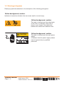
1.2 Warning pictograms
Please pay particular attention to the description of the following pictograms:
Yellow background, caution.
Indicates a hazardous situation that can cause small or severe injury.
Yellow background, caution.
This label is located near the wheel-work
of the chain. It indicates a high risk of
injury to your fingers if they get stuck
between the wheel-work and the chain.
9139157
CAUTION
ELECTRICAL HAZARD
AUTHORIZED SERVICE
PERSONNEL ONLY
Yellow background, caution.
This label is located near the main power
supply.
It indicates that this power supply cabinet
may be opened only by qualified
personnel.
9199681
Operator Manual Initial issue: 05/11
Page 9 - 6
Latest revision: 10/11/11
22,5"
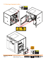
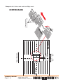
1.3 Warning pictograms location
CAUTION
ELECTRICAL HAZARD
AUTHORIZED SERVICE
PERSONNEL ONLY
CA
UT
ELEC
TRIC
AUTH
AL
ORIZ HAZA
PERS
ED
RD
ONN
SERV
EL
ONL ICE
Y
IO
N
CAUTION
ION
UT
CA
ELECTRICAL HAZARD
RD
HAZA ICE
AL
SERV
TRIC
ED
ELEC
ORIZ L ONLY
AUTH
ONNE
PERS
AUTHORIZED SERVICE
PERSONNEL ONLY
Operator Manual Initial issue: 05/11
Page 9 - 7
Latest revision: 10/11/11
22,5"
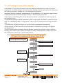
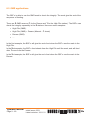
1.4 Job Definition Format (JDF) Capability
A new Web to Finish solution makes touch less workflow achievable from order to finished
product with no manual setup or intervention; thus, helping automatic print production by giving
the finishing devices an integral role in the manufacturing process.
Integrating finishing equipment capabilities into the job definition at the prepress stage reduces
or eliminates operator involvement and reduces or eliminates job setup time.
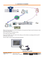
A new device, called Bourg Box, allows all on-line products to communicate with any type of
Xerox digital printer.
The WorkFlow Manager (WFM) embedded in BSF-x GUI allows the BCME-x (optional) and the
BSF-x of a BB/BCME-x/BSF-x configuration, to be set up for jobs and service using the BSF-x
GUI.
The WFM uses a digital job ticket to set up the finishing equipments automatically.
The job ticket is an XML based file format standard for information exchange in the graphic
arts environment.
The JMF synchronization between Ultimate Bindery and the Bourg finisher informs Ultimate
Bindery of the finisher status. When the finisher is ready, Ultimate Bindery releases the job at
the FFPS queue and the job is printed and finished.
Note: - Press should have software FFPS version 7.0 SP3 and higher.
- JDF mode is only enabled with the optional Bourg JDF Kit.
FreeFlow Web
Services
Solution Workflow Diagram
1
JDF instructions and PDF file via JMF
FreeFlow Process
Manager
2
PDF File via Hot Folder
Ultimate Impostrip
OnDemand Digital
3
Imposed PDF is
submitted via IPP
FFPS returns Job ID
Ultimate Bindery
4
Release job via IPP
Xerox FreeFlow
Print Server
Finishing setup info
passed in JDF via JMF
5
Xerox iGen4 Press
6
DFA level 1
Bourg Box
7
GUI
CAN
BIP
BSF-x
BIP
Operator Manual Initial issue: 05/11
Page 9 - 8
CAN
Latest revision: 10/11/11
22,5"
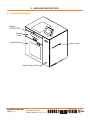
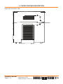
2. Machine Description
2.1 General Description
Buttons
START/STOP
Drawer
(Tray)
High Pile Door
Paper output
Input Conveyor Door
Operator Manual Initial issue: 05/11
Page 9 - 9
Latest revision: 10/11/11
22,5"
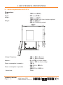
3. BSF-X Technical Specifications
3.1 Space requirements for BSF-x
Dimensions
-- 1229 mm (48.38")
Width :
-- 913 mm (35.94")
Depth :
-- 1316 mm (51.81")
-- 1626 mm (64") with User Interface optional
Height :
-- 450 Kg (992 Lbs)
-- 500 Kg (1102 Lbs) packed
Weight :
880mm
34.6”
-- 120 V - 60 Hz (1phase).
-- 230 V - 50 Hz (1phase).
Voltage/ Frequency :
-- 6 A at 230 Vac input voltage.
-- 10 A at 120 Vac input voltage.
Ampere :
Power consumption in stand-by :
Power consumption in operation :
-- 160 W
-- 546 BTU/H - 200 VA.
-- 720 W
-- 2460 BTU/H - 980 VA.
-- 75 dB.
- Noise level :
Operator Manual Initial issue: 05/11
Page 9 - 10
310mm
12.2”
610mm
24”
913mm
36"
1229mm
48.38"
Latest revision: 10/11/11
22,5"
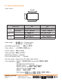
3.2 Technical specifications
- Paper format :
Crosstrack
Intrack
Paper Path
Paper size
Drawer
High Pile
By Pass
Min
8” = 203,2 mm
4.73" = 120 mm
8” = 203,2 mm
7” = 177,8 mm
8” = 203,2 mm
4.73" = 120 mm
In-track
Cross track
In-track
Cross track
In-track
Cross track
Max
22.5” = 571,5 mm
14.33" = 364 mm
22.5” = 571,5 mm
14.33" = 364 mm
26" = 660,4mm
14.33" = 364 mm
- Paper weight :60-300 gsm – Uncoated paper.
60-350 gsm – Coated paper.
- Input/Output paper height :
- Paper velocity :
860 mm (33.9").
from 1000 to 2000 mm/s.
- Drawer capacity : 140 mm (5.5").
- Paper pile height :500 mm (19.7").
- Miss/Double detection : Standard.
- End of set detection OMR :
Standard.
- Bar Code reader :Optional (from 1 to 4 Bar Code readers).
- Cart compatibility :- XEROX : DT6180-6135 / Nuvera with DS3500 & 5000.
- IGEN.
- HP Indigo Press (pallet and cart).
- KODAK / Canon
Digimaster / Digisource
- XEROX DocucolorDC 6000 - 7000 - 8000
- XEROX ColopressCP800 / 1000
4112 / 4127
- XEROX
- OCE Varioprint 6
000 Series (6250 - 6320 - 6200 - 6160,...)
4000 Series (4120 - 4110, ...)
Operator Manual Initial issue: 05/11
Page 9 - 11
Latest revision: 13/03/12
22,5"
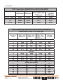
- Productivity :
BSF Productivity (SHEETS/H) in NEAR LINE MODE
Paper Format
A4 LEF (210mm)
A4 SEF (297mm)
A3
SRA3
BSF - BME BSF - BDF
2000 mm/s 1850 mm/s
14255
12160
10068
9663
BSF - BCME - BME
BSF - BCME - BDF
1300 mm/s
13973
11816
9700
9294
12278
9997
7917
7534
Watkiss
PSQ 200
1020mm/s
10865
8640
6701
6353
BSF Productivity (BOOKLETS/H) in NEAR LINE MODE
Manual Mode or OMR LE or center OMR
Number of
sheets
BSF - BME
2000 mm/s
3
6
10
15
22
1825
1182
804
575
411
3
6
10
15
22
2013
1345
933
674
486
3
6
10
15
22
50
BSF - BDF
1850 mm/s
A3
Watkiss
PSQ 200
1590
992
661
466
330
655
655
574
402
283
1818
1176
800
571
408
655
655
655
504
358
A4 SEF with rotation
Operator Manual Initial issue: 05/11
Page 9 - 12
1788
1151
781
557
397
A4 SEF
1985
1320
912
658
474
BSF - BCME BME BSF BCME - BDF
1300 mm/s
Latest revision: 10/11/11
655
655
655
613
440
206
22,5"
4. Paper Process Description
Paper path schematic view.
Operator Manual Initial issue: 05/11
Page 9 - 13
Latest revision: 10/11/11
22,5"
5. Use of BSF-x
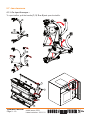
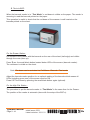
5.1 Power ON/OFF the BSF-x
Bo
ur
g
Bo
x
A
1) Open the conveyor door.
2) Switch ON/OFF the BSF-x using the Main switch (A).
The button is highlighted when the machine is ON.
3) Close the conveyor door.
5.2 Machine Line Power ON procedure
5.2.1 BSF-x - Bourg Box - Downstream Device :
Switch ON the BSF-x.
Switch ON the Bourg Box.
Switch ON the Downstream Device.
Operator Manual Initial issue: 05/11
Page 9 - 14
Latest revision: 10/11/11
22,5"
5.3 Use of Drawer and High Pile handles
There are 3 status for the Drawer and High Pile tray :
1) Ready : The tray is up and ready to feed.
2) Down : The tray is at the bottom position.
3) Offline : The tray is stopped between the up and down position. The tray is not used.
The drawing below shows the logic of Drawer and High Pile Handle buttons.
5.4 Use of START/STOP buttons
From any state (Ready, Offline or Down) press green button (START) to start the feeding.
Press black button (STOP) to stop the feeding.
While feeding, press High Pile or Drawer button to make a PAUSE.
Press again the green button (START) to restart the feeding.
Press the black button (STOP) to stop the pause and the feeding.
Operator Manual Initial issue: 05/11
Page 9 - 15
Latest revision: 10/11/11
22,5"
5.5 Drawer loading
(1)
(1)
1) Open the Drawer.
Note: To open the Drawer, it must be in down position.
2) Move the stops.
3) Place paper properly in the Drawer.
4) Adjust the paper guides. Pay attention not to damage the paper edges.
5) Close the Drawer.
Intrack
Crosstrack
Note: Install the Magnetic Stops (1) on the paper guides
when using paper format from 4.73" (120 mm) to
7" (177,8 mm) is the crosstrack direction.
Feeding accuracy is also improved in the Drawer
when using the paper stops (1) for small paper
format in the intrack direction (paper format less
than 260 mm).
Paper Path
Operator Manual Initial issue: 05/11
Page 9 - 16
Latest revision: 10/11/11
22,5"
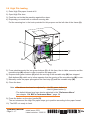
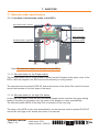
5.6 High Pile loading
1) Enter High Pile paper format at UI.
2) Open High Pile door.
3) Push the cart inside the machine against the stops.
4) Depending on model with or without securing bar.
Put the securing bar in the hook provided for this purpose on the left side of the frame (H).
G
H
M
F
D
T
5) Press simultaneously the two green buttons (G). At this time, the air table connects and the
movable stop (M) moves in order to position the paper pile.
6) Depress both green buttons (G) when the moving of the movable stop (M) has stopped.
Both buttons (G) switch on to inform operator that the moving of the movable stop (M) is over.
7) Manually move the paper pile against the fixed stop (F) and the movable stop (M).
8) Close the door.
Note: - The blower level can be adjusted by - the RH green button (+).
- the LH green button (-).
- The default blower level can also be adjusted in the "Preference Menu"
(see chapter "6.6 BSF-x Preference Menu", page 39.
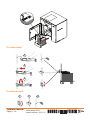
9) Press the button on the door handle (D).
The cart raises and the High Pile paper stops go in position according to the paper format.
10) The BSF-x is ready to feed.
Operator Manual Initial issue: 05/11
Page 9 - 17
Latest revision: 13/03/12
22,5"
To clamp stack
1
2
3
To release stack
1
2
3
Operator Manual Initial issue: 05/11
Page 9 - 18
Latest revision: 10/11/11
22,5"
5.7 Jam clearance
5.7.1 For Input Conveyor :
To open baffles, pull the handle (1, 2, 3 or 4) and open the baffle.
1
3
2
4
1
3
2
4
1
2
3
4
Operator Manual Initial issue: 05/11
Page 9 - 19
Latest revision: 10/11/11
22,5"
5.7.2 For By-Pass Conveyor :
Open the Drawer and use to knurled knob (5) to dejam the By-Pass Conveyor.
Open also the conveyor door (6) to turn easily the knurled knob.
6
5
Operator Manual Initial issue: 05/11
Page 9 - 20
Latest revision: 10/11/11
22,5"
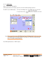
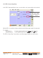
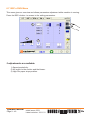
6. Use of Graphical User Interface
The User Interface is a touch screen.
Select your choice by pressing on the screen with your finger.
The User Interface is divided into several tabs that vary according to the configuration.
Each tab has its own preference and/or adjustment buttons.
The control buttons are common to all tabs.
Software version / Date
Tabs
Adjustment buttons
Control buttons
Care and cleaning
Do not place anything on the screen.
Do not let liquid get on or into the screen.
Use a regular glass cleaner to clean the screen (proceed as explained below).
To clean the screen:
1) Switch off the BSF-x.
Do not use a spray cleaner on the screen, because the cleaner may drip inside.
2) Wet a soft cotton cloth with the cleaning solution and gently wipe the screen.
3) Do not use cleaning solutions containing solvents. Dry with a clean, soft cotton cloth.
CAUTION: Danger of explosion if battery is wrongly replaced. Replace only with the
same or equivalent type recommended by the manufacturer. Dispose of used
batteries according to the manufacturer's instructions. See Section Adjustment/
Replacement of Service Manual for battery replacement.
Operator Manual Initial issue: 05/11
Page 9 - 21
Latest revision: 13/03/12
22,5"
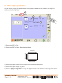
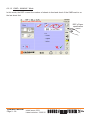
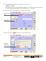
6.1 BSF-x Paper Specification
On this screen, enter the specifications for the paper loaded into the Drawer, the High Pile
station and/or the By-Pass.
1
3
4
5
2
1) Select the BSF-x Tab.
2) Select the BSF-x Paper Specifications Menu.
Crosstrack
Intrack
Paper Path
3) Select the paper format for the intrack and crosstrack dimensions.
4) Select the paper weight (in gsm).
5) Select "Apply to High Pile" to copy the paper format of the Drawer to the High Pile station.
Operator Manual Initial issue: 05/11
Page 9 - 22
Latest revision: 10/11/11
22,5"
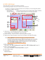
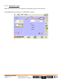
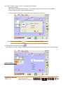
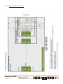
6.2 BSF-x Edit Subset
This menu allows to setup the sequence of feeding.
In the following example, there are 2 subsets in the current job.
A subset is a sequence of feeding sheets from the Drawer or from the High Pile station.
In this case, the BSF-x will feed :
1 sheet (manual mode) from the Drawer station (Max 6 subsets).
- First (subset 1) :
- Second (subset 2) : 10 sheets (manual mode) from the High Pile station.
7
4
5
2
1
3
6
1) Job preview : This area gives a preview of the current job.
In this example, there are 2 subsets in the current job.
2) Subset selection : Press the button to select the subset and edit it.
3) Paper source :Select the paper source from the Drawer or the High Pile station.
Note: When “By-Pass” is selected, the paper is coming from the printer.
The BSF feeding modes (manual, OMR, Barcode mode) are not available.
The paper process and the “end of set” are controlled by the printer.
It is also possible to insert a cover from the Drawer or from the High Pile
(see "6.2.1 BSF-x Feeding mode", page 24.
4) BSF-x feeding mode :
See chapter "6.2.1 BSF-x Feeding mode", page 24"6.2.1 BSF-x Feeding mode", page 24.
5) BSF-x Custom paper Menu :
See chapter"6.2.2 BSF-x Custom Paper Menu", page 29 .
6) Add or delete subset.
7) Clear button :
Erase all subsets.
Operator Manual Initial issue: 05/11
Page 9 - 23
Latest revision: 13/03/12
22,5"
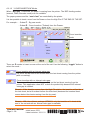
6.2.1 BSF-x Feeding mode
The BSF-x has 4 modes of feeding : -
-
“MANUAL” mode.
“OMR” Mode.
“OMR + MANUAL” Mode.
“BARCODE” Mode.
“COVER INSERTION” Mode.
6.2.1.1 “MANUAL” Mode
In the manual mode, the BSF-x will count the number of sheets to feed.
If activated, select the number of sheets to feed from the Drawer or from the High Pile station.
Select the
number of sheets
Operator Manual Initial issue: 05/11
Page 9 - 24
Latest revision: 10/11/11
22,5"
6.2.1.2 “OMR” Mode
OMR = Optical Mark Recognition.
A little mark printed on the paper gives the end of the subset feeding sequence.
The BSF-x has 2 OMR modes : - LE Last (Lead Edge Last) : T
he OMR mark is on the lead
edge of the last sheet.
- C Last (Center Last) : The OMR mark is centered on the last
sheet.
Note: There is also the modes “LE All but last” and “C All but last”. In this case, there
is an OMR mark on all sheets except on the last one. The lack of mark gives the
end of the subset feeding sequence.
See OMR specifications in “OMR” chapter.
Operator Manual Initial issue: 05/11
Page 9 - 25
Latest revision: 13/03/12
22,5"
6.2.1.3 “OMR + MANUAL” Mode
In this mode, the BSF-x count the number of sheets to feed and check if the OMR mark is on
the last sheet fed.
BSF-x Paper
specification
menu
Operator Manual Initial issue: 05/11
Page 9 - 26
Latest revision: 13/03/12
22,5"
6.2.1.4 “BARCODE” Mode
With the barcode mode, the sequence of feeding is given by the barcode.
See BARCODE specifications in “BARCODE” chapter.
Operator Manual Initial issue: 05/11
Page 9 - 27
Latest revision: 13/03/12
22,5"
6.2.1.5 “ COVER INSERTION” Mode.
When “By-Pass” is selected, the paper is coming from the printer. The BSF feeding modes
(manual, OMR, Barcode mode) are not available.
The paper process and the “end of set” are controlled by the printer.
It is also possible to insert a cover from the Drawer or from the High Pile AT THE END OF THE SET.
For example : - Subset 1 : By-pass mode.
- Subset 2 : Cover Insertion (1 sheet) from the Drawer.
Cover insertion
mode
There are 2 modes to insert a cover at the end of the set. Use the following “toggle” button to
select the mode :
Cover insertion with an interset extra gap:
The cover will be sent to the finisher after the last sheet coming from the printer
(with no overlap).
Cover insertion with no interset extra gap:
The cover will be inserted with an overlap on the last sheet coming from the
printer. This application does NOT reduce the productivity because NO interset
extra gap is needed.
Remark : If the insertion comes from the High Pile station, the insertion will not be at
the last sheet, but at the sheet before the last sheet (because the inserted sheet
comes below the sheets coming from the by-pass).
Remark : With the software package WFM004, only the insertion of 1 sheet at the
end of the set and with an interset extra gap is available.
Operator Manual Initial issue: 05/11
Page 9 - 28
Latest revision: 10/11/11
22,5"
6.2.2 BSF-x Custom Paper Menu
In the “BSF-x Paper specification” menu, on each station, only 1 paper weight can be selected.
Only 1 paper
weight for each
station
With the BSF-x, it is possible to feed pre-collated sets with different paper weight in the same pile.
For example :
- First (subset 1) :
- Second (subset 2) :
10 sheets (manual mode) from the Drawer station (90 gsm).
1 cover (manual mode) from the Drawer station (250 gsm).
The “BSF-x Custom Paper” menu allows to set different paper weights in the same station.
Operator Manual Initial issue: 05/11
Page 9 - 29
Latest revision: 13/03/12
22,5"
1) For the example above, program 2 subsets from the Drawer :
- subset 1 = 10 sheets.
- subset 2 = 1 cover.
Both subset are set up with 90 gsm paper weight. The “Custom paper” menu will be used
to select a different paper weight for the 2nd subset (cover – 250 gsm).
2) Select the subset N°2 and press on the “Custom Paper” menu.
Custom paper
menu
Subset N°2
3) Press on the button
to enable the “Custom paper” mode.
Enable the
« Custom
paper » mode
Operator Manual Initial issue: 05/11
Page 9 - 30
Latest revision: 13/03/12
22,5"
4) In the “Custom Paper” menu, 2 settings are available:
- The paper weight.
- The simple and double sheet mode. The double sheet mode allows to feed folded
sheets, carbon paper, sheets stitch together,…
In this example, the paper weight has been changed to 250 gsm.
Note: Press on the button
to disable the “Custom Paper” mode.
.
5) Validate the setting by pressing
The subset is in the “orange” color to prevent the operator that this subset uses custom paper.
Custom subset
Operator Manual Initial issue: 05/11
Page 9 - 31
Latest revision: 13/03/12
22,5"
6.3 BSF-x Speed Menu
2
1
1) Speed :
Select the BSF-x speed from 1 to 9 (low = 1, high = 9).
2) Turbo mode:
Enable or disable the Turbo mode.
- If the turbo mode is disabled (turbo mode = 0), the BSF-x blows air on 1 station at a time.
So when the feeding changes from the High Pile to the Tray, the BSF-x will stop to
blow air in the High Pile and will after start to blow air in the Tray. This change takes
time and decrease the productivity.
- If turbo mode is enabled (turbo mode = 1), the BSF-x blows air in both stations
(High Pile and Tray) at the same time.
So, there is no loss of time when the feeding changes to feed from the High Pile to
the Tray (or reverse).
Note: The turbo mode is useful ONLY when the job is feeding sheets from both station
(High Pile and Drawer).
If the job is feeding only from one station, the turbo mode is not needed.
Operator Manual Initial issue: 05/11
Page 9 - 32
Latest revision: 10/11/11
22,5"
6.4 BSF-x Error mode Menu
Select BSF-x behavior in case of errors (double feed) :
- Stop on sheet : S
top at the first error. If error, the double sheets are stopped in the
BSF-x conveyor, and the previous feeded sheets stay in the
Downstream Device.
The operator has to purge the paper.
- Stop on set : S
top at end of set. If error, the double sheets and the other sheets of the
booklet are feeded into the Downstream Device. The Downstream Device
will purge automatically the entire faulted set and will stop after.
- No stop and purge error set : N
o stop in case of error(s). If error, the faulted set will
be purged (without folding and stitching) without
stopping the machines.
Operator Manual Initial issue: 05/11
Page 9 - 33
Latest revision: 10/11/11
22,5"
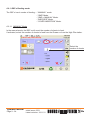
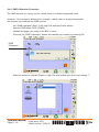
6.5 BSF-x File menu parameter
The graphical interface allows an easy and performing jobs management.
Press the button "FILE MENU" to have access to the file parameters.
Five adjustments are available:
1
2
3
4
1 - Make a comment on the saved jobs.
2 - Open a job saved by the operator.
3 - Save a new program with his name and characteristics.
4 - Erase an existing program no longer used.
Operator Manual Initial issue: 05/11
Page 9 - 34
Latest revision: 10/11/11
22,5"
Make a comment
This menu allows to make a personal comment on a saved job.
1
Select a job and press button (1) to access to the dialogue box.
4 lines are available to write the comments through the alphanumeric keyboard.
Press enter to display the comment on the line.
Validate
.
Operator Manual Initial issue: 05/11
Page 9 - 35
Latest revision: 10/11/11
22,5"
Opening an existing job
This menu allows to open a job saved by the operator.
2
Select a job in the left column and press button (2).
Press YES to open the selected job or NO to return to the previous screen and select another job.
This job can be the starting point to define a new job.
If set, this option can be changed in the preferences menu.
Operator Manual Initial issue: 05/11
Page 9 - 36
Latest revision: 10/11/11
22,5"
Save a job
3
When a job has been defined by the operator, it can be saved as follow.
Press button (3).
Enter a name for the job on the alphanumeric keyboard and confirm it with the “ENTER” key.
The new job appears in the left column.
If the name given already exists and that you press “enter”, a message will appear to ask you
to confirm the replacement of an existing file by the new one.
Press YES to replace the existing job by the new one or NO to return to the previous screen
and rename the new job.
Note: Approximately 500 jobs can be stored.
Operator Manual Initial issue: 05/11
Page 9 - 37
Latest revision: 10/11/11
22,5"
Erasing a job
This menu allows to erase an existing job.
4
ATTENTION: : Once deleted, there is no way to recover the deleted program.
Select the job to be erased in the left column.
Press button (4).
The following screen appears.
Press YES to erase the selected job or NO to cancel and return to the previous screen.
Operator Manual Initial issue: 05/11
Page 9 - 38
Latest revision: 10/11/11
22,5"
6.6 BSF-x Preference Menu
With the “PREFERENCES” menu, the BSF-x can be configured according to the operator’s preference.
There are 4 operator’s settings: - Blower level when loading High Pile (1).
-Barcode Definition (2).
-OMR Calibration (3).
-Barcode Test (4).
The “PREFERENCES” menu is available in the BSF-x tab by pressing the icon
4
.
2
3
1
BSF-x
Preferences
menu
1) Blower level when loading High Pile.
When loading paper in the High Pile station, the operator open the High Pile door, push
the cart into the BSF-x and presses on the 2 green buttons. At this time, the blower starts
to blow through the air table. With the air table, the operator can easily move/rotate the
paper pile.
By default, the blower air level is at the maximum.
However, the blower level can be adjusted and decrease according to the height of the
paper pile.
If there is no air table on the cart, the blower air level can be also switch off.
2) Barcode Definition : See chapter "7. Barcode", page 45.
3) OMR Calibration : See chapter "8. OMR Specifications", page 59.
Operator Manual Initial issue: 05/11
Page 9 - 39
Latest revision: 13/03/12
22,5"
4) Barcode Reader Test.
The “barcode Test” menu allows to the operator to check the barcode reading of the
scanners above the paper pile of the Drawer and the High Pile station.
A. Test via GUI:
- Put paper with barcode (face UP) in the Drawer and in the High Pile station.
- Validate the paper size setup in the BSF-x menu.
- Put on the “Barcode Test” button
. The Drawer and the High Pile trays will go up
and the High Pile paper stop will be in position (according to the paper size).
- For each station, press on :
- CONTINUOUS : T
o start the Barcode reading and the scanning continuously.
The code read is displayed on the GUI.
- SINGLE : To activate the barcode reading and the scanning during 100ms
(maximum time to read the code in the BSF-x process).
The code read is displayed on the GUI.
- Press on the blue arrow
to go out of this menu.
The “Continuous” mode is useful to place manually the Drawer barcode assembly according to
the printed barcode. In the High Pile station, the “continuous” mode is also useful to check if
the printed barcode is correctly scanned and to check the barcode scanning area.
The barcode reader has the best reading results when the scanning area begins just before
the code and continues after the code.
Operator Manual Initial issue: 05/11
Page 9 - 40
Latest revision: 13/03/12
22,5"
B. Test via BCR :
When the barcode reader is in "Test Mode", a red beam is visible on the paper. The reader is
scanning to read the barcode printed on the paper.
This operation is useful to check that the red beam of the scanner is well located on the
barcode printed on the sheet.
For the Drawer Station :
Put a sheet in the Drawer with the barcode on the rear of the sheet (trail edge) and visible
through the cover (face up).
Press 3 sec. the small black button located below LEDs of the sensor (barcode reader).
The red beam is visible on the sheet.
Note: The beam can be actuated via Pref Menu / Barcode / Test mode.
Adjust the barcode reader position for an optimal reading of the barcode which means all
LEDs (including green one) of the sensor must be ON.
Power OFF the beam by pressing the small black button again (optional).
For the High Pile Station :
The procedure to put the barcode reader is "Test Mode" is the same than for the Drawer.
The position of the reader is automatic (done with the setup of the BSF-x).
Operator Manual Initial issue: 05/11
Page 9 - 41
Latest revision: 10/11/11
22,5"
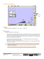
6.7 BSF-x RUN Menu
This menu gives an overview and allows parameters adjustment while machine is running.
Press the BSF-x button to access to the setting parameters.
2
1
3
3 adjustments are available:
1) Speed productivity.
2) Air levels for the suction and the blower.
3) High Pile paper stops position.
Operator Manual Initial issue: 05/11
Page 9 - 42
Latest revision: 10/11/11
22,5"
6.7.1 Adjustment of the suction and the blower levels for the feeding :
According to the paper format and the paper weight, the air levels of the suction and the
blower are setup automatically. Corrections can be applied in case of special paper.
Example:- In case of sticky paper: Increase the blower level.
- In case of heavy paper: Increase the suction level.
Press on the
button to modify the air level of the suction and the blower (1).
1
Select the subset (2) that needs air levels corrections and press ”+“ or “-” to adjust the suction
(3) and the blower (4).
2
{
3
4
Operator Manual Initial issue: 05/11
Page 9 - 43
Latest revision: 10/11/11
22,5"
6.7.2 Adjustment of the High Pile paper stops :
According to the paper format, the High Pile
paper stops are setup automatically against
the paper pile. However, corrections can be
applied in case of special paper.
For example:
- In case of paper with curl: Tighten the
paper stops.
- If the barcode reader does not scan on the
barcode printed on the paper.
Adjust the position of the rear stop (and so
the position of the barcode reader)
to have a good barcode reading.
Note : Check that the angle between paper stop and the paper
is close to 3° - 5°.
3° -> 5°
Press the
button (1) to modify the High Pile paper stops position:
- REAR Stop position adjustment (2).
- LATERAL Stops position adjustment (3).
2
1
3
Operator Manual Initial issue: 05/11
Page 9 - 44
Latest revision: 13/03/12
22,5"
7. Barcode
7.1 Barcode reader specifications
7.1.1 Locations of the barcode reader in the BSF-x
Bare code reader - Drawer
Drawer station
Paper Output
Barcode reader - High Pile
High Pile station
Cart
Note: The barcode readers are an option on the BSF-x.
7.1.1.1 Barcode reader for the Drawer station.
The barcode reader (BCR) of the Drawer is placed on the Plexiglas of the upper cover of the
BSF-x. With the magnets, the BCR can be moved easily in every position.
The barcode must be printed FACE UP and at the bottom of the sheet. But most of the time,
we put the barcode on the trail edge of the sheet.
7.1.1.2 Barcode reader for the High Pile station.
In the High Pile station, there are rear and lateral stoppers which maintain the paper during
feeding. According to the paper size, the setup of the stoppers is done automatically.
The barcode reader (BCR) of the High Pile is mounted on the rear stop.
The setup of the BCR is also done automatically, but the barcode must be printed FACE UP
and on the trail edge of the sheets and center in crosstrack.
Operator Manual Initial issue: 05/11
Page 9 - 45
Latest revision: 13/03/12
22,5"
7.1.2 Current locations of the barcode on the paper
7.1.2.1 For the Drawer station
Operator Manual Initial issue: 05/11
Page 9 - 46
Latest revision: 10/11/11
22,5"
Drawer Barcode reader position :
Barcode reader
position by default
Paper Process
Barcode reader
in reverse position (180°)
Paper Process
Note: - The Barcode reader can be turned of 90° to read barcode perpendicular to
the paper path.
- With the first barcode kit (9591941), the minimum barcode height printed on
the paper is 10 mm.
Operator Manual Initial issue: 05/11
Page 9 - 47
Latest revision: 10/11/11
22,5"
7.1.2.2 For the High Pile station :
Operator Manual Initial issue: 05/11
Page 9 - 48
Latest revision: 10/11/11
22,5"
7.1.3 Code definition
The code used is code 39.
The barcode definition is given on each sheet. The barcode MUST be on the upper face of the paper.
The barcode definition can be defined by the user on the GUI.
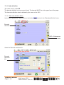
7.1.3.1 Barcode definition Menu
In the “BSF-x preference” menu, press on the button
to enter in the “Barcode definition” menu.
Barcode
definition
BSF-x Preferences
menu
Select the Barcode definition N°1.
Barcode
definition
N°1
Operator Manual Initial issue: 05/11
Page 9 - 49
Latest revision: 18/01/12
22,5"
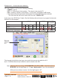
The following screen explains the way to program the barcode definition:
Barcode
definition
menu
BSF-x Preferences
menu
The default barcode definition has 3 fields and is like : aaaabbcc :
•aaaa = job ID (reference number of the job).
•bb = n° of the sheet of the booklet.
•cc = number of sheets in the booklet.
The barcode sheet counter can also be selected as N1 and 1N.
•N1 : The cover is the LAST sheet fed and has the sheet number 1.
This mode is the default mode for CP Bourg finishers (BDFE, BME,….).
• 1N : The cover is FIRST sheet fed and has the sheet number 1.
This mode is specific for Watkiss PSQ200 bookletmaker. The stitching head are
from the bottom, so the cover is fed first, and afterward the content of the booklet.
Example N°1 – With the default barcode definition:
The code “9999 01 05” has the following meaning:
• 9999 = job ID.
• 01 = n° of the sheet of the booklet – This sheet is the sheet N°1.
• 05 = number of sheets in the booklet – In this case, the booklet has 5 sheets.
•This sheet will be the last sheet fed because the mode N1 has been selected.
The first sheet fed will be the sheet with the code “9999 05 05”.
The following tab explains the barcode definition:
JOB ID
CODE
FIELD
DIGIT POSITION
LENGTH OF THE FIELD
9
a
1
Operator Manual Initial issue: 05/11
Page 9 - 50
9
9
a
a
2
3
4 Digits
Latest revision: 18/01/12
9
a
4
SHEET N°
NUMBER
OF SHEET
0
1
b
b
5
6
2 Digits
0
5
c
c
7
8
2 Digits
22,5"
Example N°2 – Custom barcode definition:
The code “22222 01 05” has the following meaning:
• 22222 = job ID.
• 01 = n° of the sheet of the booklet – This sheet is the sheet N°1.
• 05 = number of sheets in the booklet – In this case, the booklet has 5 sheets.
•This sheet will be the last sheet fed because the mode N1 has been selected.
The first sheet fed will be the sheet with the code “22222 05 05”.
In this case, the JOB ID has 5 digits. See the following tab and screen to program the barcode
definition for this example.
JOB ID
CODE
FIELD
DIGIT POSITION
LENGTH OF THE FIELD
2
a
1
2
a
2
2
2
a
a
3
4
5 Digits
2
a
5
SHEET N°
NUMBER
OF SHEET
0
1
b
b
6
7
2 Digits
0
5
c
c
8
9
2 Digits
Barcode
definition
N°2
This barcode job definition has been stored with the barcode job definition N°2.
Up to 10 different barcode job definition can be stored in the GUI.
Note: With the software package WFM 03.00.02 (TAG BSF-x 431 – Soft GUI minimum
05.04.90), the first digit begin to “1” (see “digit position” line in the tab above).
With previous software version, the first digit begin to “0”.
Operator Manual Initial issue: 05/11
Page 9 - 51
Latest revision: 18/01/12
22,5"
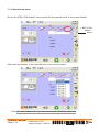
7.1.4 Barcode job setup
Go into the “BSF-x Edit Subset” menu and select the barcode mode in the current subset.
« BSF-x Edit
subset »
Menu
Select also the number of the code definition in the current subset.
Note: For each subset of the job, the code definition MUST be the same.
Operator Manual Initial issue: 05/11
Page 9 - 52
Latest revision: 13/03/12
22,5"
7.1.5 Current barcode applications
There are 6 operational applications.
The applications 1, 2, 3 and 4 are specific for CP Bourg bookletmaker.
The barcode sheet counter is N1.
The applications 5 and 6 are specific for Watkiss PSQ200 bookletmaker.
The barcode sheet counter is 1N.
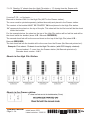
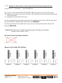
7.1.5.1 Feeding “X” sheets from the High Pile station + “X” sheets (cover) from the Drawer
with integrity checked in the High Pile station AND in the Drawer
X can be 1, 2,... or N sheets,.… Barcode is checked in the High Pile station and in the Drawer.
The cover must be printed separately (with barcode) and placed in the Drawer station.
The content of the booklet MUST BE PRINTED 1N and placed in the High Pile station.
“N” represents the sheet on the top of the pile. This sheet will be the fed first and will be the
sheet inside the booklet.
“1” represents the last sheet fed (Cover).
For the example below, the sheet on the top of the High Pile station will be the first sheet fed
and will be the sheet inside the booklet (sheet N°6 - Barcode 00000606).
The second sheet fed will be the second sheet on the top of the High Pile
(sheet N°5 – Barcode 00000506).
The last sheet fed into the booklet will be the cover from the Drawer (sheet N°1 - Barcode 00000106).
Example: First subset : 5 sheets from the High Pile station (with BCR integrity checked).
Second subset : 1 cover from the Drawer station (with BCR integrity checked).
Barcode sheet counter : N1.
Sheets in the High Pile Station:
Sheets in the Drawer station:
Operator Manual Initial issue: 05/11
Page 9 - 53
Latest revision: 13/03/12
22,5"
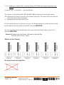
7.1.5.2 Feeding “X” sheets from the High Pile station + “X” sheets from the Drawer with
integrity checked only in the High Pile station (not in the Drawer station).
X can be 1, 2,... or N sheets,.…
Barcode is checked ONLY in the High Pile (NOT in the Drawer station).
The cover must be printed separately (without barcode) and placed in the Drawer station.
The content of the booklet MUST BE PRINTED 1N and placed in the High Pile station.
“N” represents the sheet on the top of the pile. This sheet will be fed first and will be the sheet
inside the booklet.
For the example below, the sheet on the top of the High Pile station will be fed first and will be
the sheet inside the booklet (sheet N°5 - Barcode 00000505).
The second sheet fed will be the second sheet on the top of the High Pile (sheet N°4 –
Barcode 00000405).
The last sheet fed into the booklet will be the cover from the Drawer (No Barcode printed on!).
Example: First subset : 5 sheets from the High Pile station (with BCR integrity checked).
Second subset : 1 cover from the Drawer station (No Barcode printed on!).
Barcode sheet counter : N1.
Sheets in the High Pile Station:
Sheets in the Drawer station:
Operator Manual Initial issue: 05/11
Page 9 - 54
Latest revision: 13/03/12
22,5"
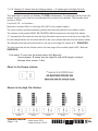
7.1.5.3 Feeding “X” sheets ONLY from the High Pile STATION with integrity checked.
X can be 1, 2,... or N sheets,.… from the High Pile.
The content of the booklet MUST BE PRINTED 1N and placed in the High Pile station.
“N” represents the sheet on the top of the pile. This sheet will be fed first and will be the sheet
inside the booklet.
“1” represents the last sheet fed (Cover).
For the example below, the sheet on the top of the High Pile station will be fed first and will be
the sheet inside the booklet (sheet N°6 - Barcode 00000606).
The last sheet fed into the booklet will be the cover from the High Pile station (sheet N°1 Barcode 00000106).
Example: 6
sheets from the High Pile (with barcode). NO sheet in the Drawer.
Barcode sheet counter : N1.
No sheet from the Drawer station:
Sheets in the High Pile Station:
Operator Manual Initial issue: 05/11
Page 9 - 55
Latest revision: 13/03/12
22,5"
7.1.5.4 Feeding “X” sheets ONLY from the Drawer STATION with integrity checked in the
Drawer.
X can be 1, 2,... or N sheets,.… from the Drawer.
The content of the booklet MUST BE PRINTED 1N and placed in the Drawer station.
“N” represents the sheet on the top of the Drawer paper pile. This sheet will be fed first and
will be the sheet inside the booklet.
“1” represents the last sheet fed (Cover).
For the example below, the sheet on the top of the Drawer paper pile will be fed first and will
be the sheet inside the booklet (sheet N°6 - Barcode 00000606).
The last sheet fed into the booklet will be the cover from the Drawer station (sheet N°1 Barcode 00000106).
Example: 6
sheets from the Drawer. NO sheet in the High Pile.
Barcode sheet counter : N1.
Sheets in the Drawer:
No sheet from the High Pile:
Operator Manual Initial issue: 05/11
Page 9 - 56
Latest revision: 13/03/12
22,5"
7.1.5.5 Feeding “X” sheets from the Drawer station + “X” sheets from the High Pile with
integrity checked in the Drawer AND in the High Pile station.
This application is specific for Watkiss PSQ200 bookletmaker. The stitching head are from the bottom,
so the cover is fed first, and afterward the content of the booklet. The barcode sheet counter is 1N.
X can be 1, 2,... or N sheets,.…
Barcode is checked in the Drawer and in the High Pile station.
The cover must be printed separately (with barcode) and placed in the drawer station.
The content of the booklet MUST BE PRINTED N1 and placed in the High Pile station.
“1” represents the 1st sheet of the booklet (COVER) and must be loaded in the drawer.
For the example below, the first sheet fed will be the cover from the drawer station - (sheet
N°1 – COVER – Barcode 00000106).
The second sheet fed will be the sheet on the top of the High Pile (sheet N°2 – 00000206).
The last sheet fed into the finisher will be the last page of the booklet (sheet N°6 – Barcode
00000606).
First subset :1 cover from the drawer station (with BCR integrity checked).
Second subset : 5 sheets from the High Pile (with BCR integrity checked).
Barcode sheet counter : 1N.
Sheet in the Drawer station:
Sheets in the High Pile Station:
Operator Manual Initial issue: 05/11
Page 9 - 57
Latest revision: 05/12
22,5"
7.1.5.6 Feeding “X” sheets from the Drawer station + “X” sheets from the High Pile with
integrity checked only in the High Pile station (not in the Drawer station).
This application is specific for Watkiss PSQ200 bookletmaker. The stitching head are from the
bottom, so the cover is fed first, and afterward the content of the booklet. The barcode sheet
counter is 1N.
X can be 1, 2,... or N sheets,.…
Barcode is checked ONLY in the High Pile (NOT in the drawer station).
The cover must be printed separately (without barcode) and placed in the drawer station.
The content of the booklet MUST BE PRINTED N1 and placed in the High Pile station.
“1” represents the 1st sheet fed from the High Pile station and must be on the top of the High Pile.
For the example below, the first sheet fed will be the cover (without barcode) from the drawer station.
The second sheet fed will be the sheet on the top of the High Pile (sheet N°1 – 00000105).
The last sheet fed into the finisher will be the last page of the booklet (sheet N°5 – Barcode
00000505).
First subset :1 cover from the drawer station (NO Barcode).
Second subset : 5 sheets from the High Pile (with BCR integrity checked).
Barcode sheet counter : 1N.
Sheet in the Drawer station:
Sheets in the High Pile Station:
Operator Manual Initial issue: 05/11
Page 9 - 58
Latest revision: 05/12
22,5"
8. OMR Specifications
OMR = Optical Mark Recognition.
A little mark printed on the paper give the end of the sequence of feeding.
The OMR sensors are installed in standard in all BSF-x. It is not an option.
8.1 Locations of the OMR sensors in the BSF-x
2 OMR sensors are placed in the BSF-x: 1 for the Drawer and 1 for the High Pile station.
The sensors are located on the lower face of the paper path. So, the mark MUST BE printed
face down on the sheet.
Drawer OMR Sensor
High Pile OMR Sensor
Operator Manual Initial issue: 05/11
Page 9 - 59
Latest revision: 10/11/11
22,5"
8.2 Locations of mark on the paper
2 positions of the mark are possible:- Center (CE).
- At the lead edge (LE).
CE
LE
TE
LE
TE
LE
≥ 1,5mm
< 2mm
Mark
dimensions
≥ 1,5mm
< 2mm
25mm
25mm
Mark
CE
Mark
position
on sheet
≥ 4mm
≥ 12mm
≥ 12mm
Operator Manual Initial issue: 05/11
Page 9 - 60
LE
Mark
Latest revision: 05/12
≥ 3mm
≤ 5mm
22,5"
Example: with Center mark and Lead Edge mark :
CENTER MARK
N
E F
D
O AC
W E
N D FA
O
W CE
N D
E
12 mm
MIN
12 mm
MIN
Center line
Center line
1,5 mm MIN
2 mm MAX
25 mm MIN
Paper direction
FACE DOWN
F
A
C
D
U
E
C
FA
180°
N
O
W
P
FA
C
Blank area without
text or picture or mark
O
W
Operator Manual Initial issue: 05/11
Page 9 - 61
Latest revision: 10/11/11
22,5"
Page 9 - 62
Operator Manual Initial issue: 05/11
Latest revision: 10/11/11
Centered line
4 mm
MIN
1,5 mm MIN
2 mm MAX
5mm
MAX
3 mm
MIN
25 mm MIN
E
C
A
F
WN
O
D
180°
C
FA
P
U
E
E
C
A
F
WN
O
D
N
OW
D
E
FAC
WN
O
D
E
FAC
Blank area without
text or picture or mark
LEAD EDGE MARK
22,5"
8.3 OMR applications
The BSF-x is able to use the OMR mark to check the integrity. The mark give the end of the
sequence of feeding.
There are 2 OMR sensors (1 for the Drawer and 1 for the High Pile station). The BSF-x can
check the integrity separately in the 2 stations. Here are some examples:
• High Pile (OMR).
• High Pile (OMR) + Drawer (Manual – 1 sheet)
• Drawer (OMR).
• …
In the first example, the BSF-x will give the end of set when the BSF-x see the mark in the
High Pile.
In the 2nd example, the BSF-x feed sheets from the High Pile until the mark, and will feed
after 1 cover from the Drawer.
In the 3rd example, the BSF-x will give the end of set when the BSF-x see the mark in the
Drawer.
Operator Manual Initial issue: 05/11
Page 9 - 63
Latest revision: 10/11/11
22,5"
8.4 OMR Calibration definition
OMR Calibration is a printed sheet with 2 contrast areas used to detect the marks;
The detection contrast area and the background contrast area.
The sheet itself can be used as background contrast area.
A printed mark read on sheet gives to the BSF-x the end of paper feeding sequence.
A calibration should be done to define the mark contrast according to the paper background color.
The BSF-x is factory set for a black mark on a white background sheet.
It is therefore possible to calibrate the sensor for a black mark on grey or yellow background
(for example).
8.4.1 OMR Calibration sheet
The calibration sheet 9134156 (supplied with the machine) can be used as calibration sheet.
The calibration sheet can be printed with the following parameters :
- Contrast areas in centered position.
- Intrack and crosstrack dimension of the contrast area.
- Uniformity of the contrast area and sharpness lines.
Calibration sheet
< 50mm
These contrast areas and the
background of the mark to detect must
be the same colour and very regular.
Intrack middle line
Operator Manual Initial issue: 05/11
Page 9 - 64
< 50mm
≥ 50 mm
Crosstrack middle line
10mm
Latest revision: 13/03/12
This contrast area and the mark
to detect must be the same
colour and very regular.
22,5"
8.4.2 OMR Calibration Procedure
The OMR sensors are factory set for a black mark on a white background sheet.
However, if the contrast is different (for example, a black mark on a grey background),
the operator can calibrate the OMR sensors.
- Put “OMR calibration sheet” in the High Pile and the Drawer station
(with the OMR Mark FACE DOWN).
- Validate the paper size setup in the BSF-x menu.
- Press on the “OMR Calibration” button and validate your choice by pressing OK.
OMR
Calibration
- Select the sensor to calibrate (Drawer or High Pile) and validate your choice by pressing
Operator Manual Initial issue: 05/11
Page 9 - 65
Latest revision: 13/03/12
.
22,5"
-The BSF-x will feed 1 sheet from the Drawer and will read the contrast printed on the
paper to calibrate the sensor. A message appears on the GUI to prevent the operator
that the calibration is “successful” or “failed”.
Operator Manual Initial issue: 05/11
Page 9 - 66
Latest revision: 10/11/11
22,5"
9. Handheld Scanner
When the dolly stands front of the finishing line, the operator will have to pick the banner sheet
on the top of the stack.
Scan the barcode on the banner sheet.
Throw away the banner sheet.
Plug into the BSF-x the cart, wait for the setting up of the finisher accordingly with the job ID
extracted in the barcode.
Start the BSF-x then produce professional booklets.
Operator Manual Initial issue: 05/11
Page 9 - 67
Latest revision: 04/04/12
22,5"
9.1 Handheld scanner operation
If the Handheld scanner beeps 3 times when scanning a barcode, the link has not been
established. If the Handheld scanner beeps once, the link has been established.
The green LED on the base flashes to indicate the Handheld scanner’s battery is charging.
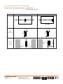
9.1.1 Beeper and LED sequences and meaning
The Handheld scanner contains LEDs on the top of the Base to indicate its power up,
communication, and battery status. Simply stated, red LED=error and green LED=success of
any type. The audible indicators of the unit have meaning as well: 3 beeps=error, 2
beeps=menu change, 1 beep=all other successes.
The table below lists the indication and cause of the LED illumination and beeps for the
Handheld scanner.
LED Indication
Beeper Indication
Cause
Red Flash
None
Battery low
Green Flash
1 beep
Successful communication or linking
Red, blinking
3 beeps
Failed communication
Green Flash
2 beeps
Successful menu change
Red, blinking
3 beeps
Unsuccessful menu change
Normal Operation
Menu Operation
Handheld Scanner LED Sequences and Meaning
9.1.2 Override Locked Handheld scanner
If you need to replace a broken or lost Handheld scanner that is linked to a base, scan the
Override Locked Handheld scanner barcode with a new Handheld scanner, and place that
Handheld scanner in the base. The locked link will be overridden; the broken or lost Handheld
scanner’s link with the base will be removed, and the new Handheld scanner will be linked.
Operator Manual Initial issue: 05/11
Page 9 - 68
Latest revision: 04/04/12
22,5"
9.1.3 Unlinking the Handheld scanner
If the base has an Handheld scanner linked to it, that Handheld scanner must be unlinked
before a new Handheld scanner can be linked. Once the previous Handheld scanner is
unlinked, it will no longer communicate with the base. Scan the Unlink Handheld scanner
barcode to unlink an Handheld scanner.
9.2 Use of Handheld Scanner
When a barcode is scanned, the following screen appears.
2
1
3
4
(1) This area displays the reading of the barcode scanned on the banner sheet.
(2) "Job ID" button: allows entering the barcode ID manually through a virtual keyboard.
(3) “ Pause” button : Saves in a “PausedJDFJobFile” file the setup of the train.
Save the counters (set - preset) per JDF job saved.
(4) " Resume” button: will load the “PausedJDFJobFile” file and make the machine train
setup. Operator will have to restart the Job. Or will allow the operator to choose in the JDF
saved list (max 50 JDF job saved).
Operator Manual Initial issue: 05/11
Page 9 - 69
Latest revision: 04/04/12
22,5"
9.3 Troubleshooting
9.3.1 Troubleshooting the Base
If the Base is not functioning properly, review the following troubleshooting to try to isolate the
problem.
- Is the red LED ON?
If the red LED is not illuminated, check that:
The power cord is connected properly and there is power at the power source.
- Is the green LED ON?
If the green LED is not illuminated, check that:
The Handheld Scanner is correctly placed on the Base.
The battery is not bad or deeply discharged. In some cases, the battery of the Handheld
Scanner may trickle charge to bring it into an acceptable level and the transition to a normal
charge cycle.
9.3.2 Troubleshooting the Handheld Scanner
Note: Make sure that the battery of the Handheld Scanner is charged.
- Is the JDF icon appears on U.I?
If not call for technical assistance. JDF is not installed or valid.
- Is the message ‘Handheld Scanner port open: "COM4" appears?
If not call for technical assistance. Handheld Scanner driver must be installed.
- Is the Handheld Scanner having trouble reading your barecode?
If the Handheld Scanner is not reading barecode well, check that the barecode is not
smeared, rough, scratched…
Operator Manual Initial issue: 05/11
Page 9 - 70
Latest revision: 04/04/12
22,5"
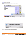
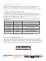
-Does the Handheld Scanner read the barcode incorrectly?
Proceed to the following test.
"Test" tab.
Ensure that the "COM" port find by Windows corresponding to the good reference "COM4
Honeywell International Inc".
Scan the barcode "123456-9$", it must appears on "Value Read:"
Operator Manual Initial issue: 05/11
Page 9 - 71
Latest revision: 04/04/12
22,5"
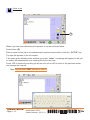
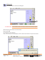
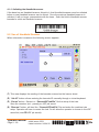
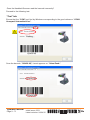
If the Handheld Scanner does not read the barcode "TEST".
Try to read the following barecodes.
Press”Done”.
When the driver is installed, the GUI reboot.
Otherwise, click on the GUI tab.
If does not success. Call for technical assistance.
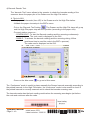
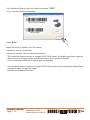
-T
he Handheld Scanner battery is charged (LED ON on base), the bright green beam appears
when you pull the trigger but the Handheld Scanner does not read barecode.
Call for technical assistance to ‘check digit’ configuration.
-T
he Handheld Scanner battery is charged (LED ON on base) but the bright green beam does
not appear when you pull the trigger.
Replace the Handheld Scanner.
Operator Manual Initial issue: 05/11
Page 9 - 72
Latest revision: 04/04/12
22,5"
10. Preventive Maintenance
Weekly :
Do a complete cleaning of the machine. Clean all mirrors of barcode readers.
If barcode readers are installed, clean the mirror and the window of the barcode assembly.
Clean the window of the Handheld Scanner with a soft cloth.
Operator Manual Initial issue: 05/11
Page 9 - 73
Latest revision: 04/04/12
22,5"
11. Environmental Compliance
11.1 Product Recycling and Disposal
ENGLISH:
Application of this symbol on your equipment is confirmation that you must dispose of this
equipment in compliance with agreed national Procedures.
In accordance with European legislation dealing with "end of life electrical and electronic
equipment", equipment subject to disposal must be managed within agreed procedures.
Prior to disposal please contact your local representative for end of life take back
information.
FRANÇAIS:
La présence de ce symbole sur cet équipement indique que ce dernier doit être mis au
rebut selon les conventions nationales.
Conformément à la législation européenne, tout équipement électrique et électronique en
fin de vie et destiné au rebut doit être manipulé selon les procédures convenues.
Veuillez contacter votre distributeur pour en savoir plus sur la reprise du matériel avant
toute mise au rebut.
ESPAÑOL:
La aplicación de este símbolo en el equipo es una confirmación de que en el momento
de deshacerse de este equipo debe de hacerlo de acuerdo con los procedimientos
nacionales acordados.
La legislación europea exige que para deshacerse de equipos eléctricos y electrónicos al
final de su duración útil deben seguirse los procedimientos acordados.
Antes de deshacerse de un equipo póngase en contacto con su distribuidor local o con el
representante para obtener información sobre su devolución.
Operator Manual Initial issue: 05/11
Page 9 - 74
Latest revision: 10/11/11
22,5"
DEUTSCH:
Geräte die dieses Symbol tragen, müssen den nationalen Richtlinien gemäß entsorgt
werden.
Den europäischen Bestimmungen zum Umgang mit elektrischen und elektronischen
Altgeräten ist Folge zu leisten.
Bei der Entsorgung des Geräts den Partner kontak-tieren.
ITALIANO:
Questo simbolo applicato sulla macchina indica la necessità di smaltire il prodotto in
conformità con le normative nazionali vigenti.
La legislazione europea richiede che lo smaltimento dei dispositivi elettrici ed elettronici a
fine vita venga gestito in conformità con le normative vigenti.
Prima di smaltire il dispositivo, rivolgersi al rivenditore autorizzato di zona per
informazioni sul ritiro dei prodotti a fine vita.
NEDERLANDS:
De aanwezigheid van dit symbool op uw apparatuur geeft aan dat u zich van deze
apparatuur moet ontdoen overeenkomstig de daarvoor in het betreffende land geldende
procedures.
Krachtens de Europese wetgeving moet de verwerking van afval van gebruikte
elektrische en elektronische apparatuur geschieden overeenkomstig de daarvoor
geldende procedures.
Neem voordat u de apparatuur wegdoet contact op met uw plaatselijke dealer of
vertegenwoordiger voor informatie over inzameling.
PORTUGUÊS:
A utilização deste símbolo no nosso equipamento confirma que deverá eliminar este
equipamento de acordo com os procedimentos adequados do seu país.
De acordo com a legislação Europeia, o fim de vida de equipamento eléctrico e
electrónico sujeito a eliminação, deverá ser realizado de acordo com procedimentos
acordados.
Antes da eliminação, contacte o seu revendedor local ou a Xerox para obter mais
informação.
Operator Manual Initial issue: 05/11
Page 9 - 75
Latest revision: 10/11/11
22,5"
NOTES
......................................................................................................................................................
......................................................................................................................................................
......................................................................................................................................................
......................................................................................................................................................
......................................................................................................................................................
......................................................................................................................................................
......................................................................................................................................................
......................................................................................................................................................
......................................................................................................................................................
......................................................................................................................................................
......................................................................................................................................................
......................................................................................................................................................
......................................................................................................................................................
......................................................................................................................................................
......................................................................................................................................................
......................................................................................................................................................
......................................................................................................................................................
......................................................................................................................................................
......................................................................................................................................................
......................................................................................................................................................
......................................................................................................................................................
......................................................................................................................................................
......................................................................................................................................................
......................................................................................................................................................
......................................................................................................................................................
......................................................................................................................................................
......................................................................................................................................................
......................................................................................................................................................
......................................................................................................................................................
......................................................................................................................................................
......................................................................................................................................................
......................................................................................................................................................
......................................................................................................................................................
Operator Manual Initial issue: 05/11
Page 9 - 76
Latest revision: 10/11/11
22,5"
Notes
......................................................................................................................................................
......................................................................................................................................................
......................................................................................................................................................
......................................................................................................................................................
......................................................................................................................................................
......................................................................................................................................................
......................................................................................................................................................
......................................................................................................................................................
......................................................................................................................................................
......................................................................................................................................................
......................................................................................................................................................
......................................................................................................................................................
......................................................................................................................................................
......................................................................................................................................................
......................................................................................................................................................
......................................................................................................................................................
......................................................................................................................................................
......................................................................................................................................................
......................................................................................................................................................
......................................................................................................................................................
......................................................................................................................................................
......................................................................................................................................................
......................................................................................................................................................
......................................................................................................................................................
......................................................................................................................................................
......................................................................................................................................................
......................................................................................................................................................
......................................................................................................................................................
......................................................................................................................................................
......................................................................................................................................................
......................................................................................................................................................
......................................................................................................................................................
......................................................................................................................................................
Operator Manual Initial issue: 05/11
Page 9 - 77
Latest revision: 10/11/11
22,5"