1
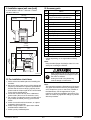
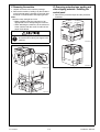
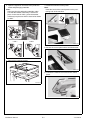
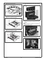
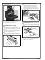
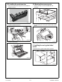
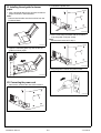
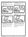
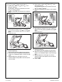
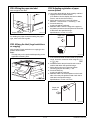
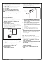
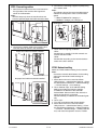
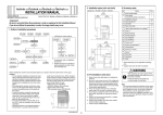
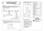
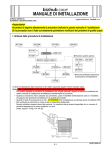
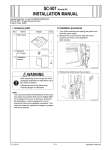
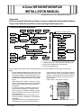
d-Color MF360/MF280/MF220
INSTALLATION MANUAL
Applied Machines:d-Color MF360/MF280/MF220
<Important>
Be sure to correctly follow the procedures in order as explained in this Installation Manual.
If you do not follow the procedure in order, the image trouble may occur.
I. Outline of installation procedures
PC-107
PC-207
PC-408
DK-507
✱ Electron system options
AU-101
WT-506
EK-604*1
Machine
AU-102
WT-507*2
AU-201
EK-605*1
MK-713
UK-203*1
KH-101
VI-505*3
SP-501
OC-509
DF-617
HD-515*4
MK-720
FK-502
Electron system options
JS-603
PK-517
SC-507
FS-527
FS-529
JS-505
IC-412*3
*1
: No particular order in installation procedures.
: Varies depending on the applicable marketing area.
*3
: Unable to be installed in d-Color MF220.
*4
: For D-Color MF220 only.
SD-509
*2
When installing the machine and associated options as a system, follow the order shown on the upper.
Note:
• For the detailed installation procedures for each
could result in personal injury. When transportoption, follow the instructions given in the correing the machine, assign an adequate number of
sponding installation manual and perform the
persons to the job and ensure that each person
procedures correctly. (Optional devices must be
can take a good position of not being excesinstalled after completing the main body instalsively loaded.
lation.)
(mass: approx. 98 kg (216-1/16 lb))
• When placing the machine on the floor, make
sure to use the paper feed cabinet or the desk
to secure the performance and the quality of
the product.
• To use this machine, install the reverse automatic document feeder or the original cover.
Even if you do not install the original cover, be
sure to install the hinge covers furnished with
the original cover.
• Once the Power Switch is turned ON, do not
turn OFF it until the installation work has been
completed.
A0EDIXC041DA
• Lifting the machine in an awkward position or
transporting it in a poorly balanced position
Y111050-6
E-1
Installation Manual
II. Installation space (unit: mm (inch))
IV. Accessory parts
d-Color MF360 + DF-617 + PC-207 + FS-527
SD-509 + MK-713
No.
1909
(75-3/16)
658
(25-7/8)
991
(39)
260
(10-1/4)
Name
1. User’s guide holder
1
2. Quick guide
(Copy/Fax/Scan/Box operations) *
1
3. Installation manual
4. User’s guide CD
5. CD-ROM
1463.2
(57-5/8)
1092.2
(43)
1 set
1
1 set
6. Paper size label
1
7. Label (Legal restrictions on copying) *
1
8. Label (Super G3 label)
1
9. Cap A (Black)
2
10. Cap B (White)
2
11. Power cord
1
12. Power cord instruction *
1
13. Cord clamp
1
14. Waste toner box
1
15. Control panel
1
16. Screw (3 × 6 mm)
1
17. Spacer
1
18. Panel pen
1
899
(35-3/8)
* Varies depending on the applicable marketing
area.
Note:
Keep the label (Super G3 label) at hand. It is necessary for mounting the FAX Kit.
255
(10-1/16)
1649.6
(64-15/16)
495.6
(19-1/2)
321
(12-5/8)
Q’ty
After unpacking, be sure to get rid of the
packaging materials and keep them out of
the reach of children.
Putting the head in the plastic bag
involves danger of suffocation.
A0EDIXC042DA
III. Pre-installation check items
1. Select a level and stable place for installing the
machine.
2. Be sure to use a power source of the voltage and
frequency indicated in the product specifications.
Ensure that the current carrying capacity of the
power outlet is at least equal to the current listed
in the product specifications.
3. Power the machine directly from a dedicated
power outlet. (Do not use an extension cord.)
4. Do not plug or unplug the power cord with wet or
dirty hands, otherwise you may get an electric
shock.
5. Avoid a hot and humid environment, or a place
exposed to direct sunlight.
6. Avoid a dusty location, or a place near volatile
and flammable substances.
7. Avoid a poorly ventilated place.
Installation Manual
Note:
This manual provides the illustrations of the accessory parts and machine that may be slightly different in shape from yours. In that case, instead of
the illustrations, use the appearance of your
machine to follow the installation procedure. This
does not cause any significant change or problem
with the procedure.
E-2
Y111050-6
V. Removing the machine
1. Unpack and remove the machine package.
2. Remove the machine, holding it by the locations
on the left side and the handles on the right side
as shown in the illustration and keeping it level.
Note:
Machine mass: 98 kg/216-1/16 lb
• Make available collective manpower of an
appropriate size for transporting the machine.
• When attaching the machine, as the reference
fit the machine with the corner A and B of the
paper feed cabinet.
VI. Removing protective tape, packing and
other shipping materials / Installing the
control panel
1. Remove the protective tapes and the protective
materials.
When holding the transportation handles,
be careful not to catch your fingers in the
machine.
A0EDIXC003DA
A0EDIXE037DA
A0XWMXC102MA
A
B
Y111050-6
A0EDIXC002DA
E-3
Installation Manual
2. Open the right door and remove the protective
sheet and packaging materials.
Note:
After removing the packaging materials, make
sure that the transfer roller assy is secured in
place. In the case of <NG>, press the transfer
roller assy into place so that it is secured as shown
in <OK>.
< OK >
4. Install the furnished control panel.
Note:
Insert the hook of the control panel into the positioning hole of the machine.
< NG >
A0EDIXC008DA
5. Secure the control panel with a furnished screw.
A0EDIXC006DB
3. Remove the packing bracket.
A0EDIXC009DA
6. Connect the machine connector to the control
panel.
A0EDIXC007DA
A0EDIXC010DA
Installation Manual
E-4
Y111050-6
7. Remove the protective sheet.
10. Open the front door and remove the protective
tape.
A0EDIXC011DA
8. Slide out the 1st drawer and remove protective
tape from the inside of the drawer.
A0EDIXC014DA
11. Remove the protective materials from the four
places.
Note:
Keep the protective materials. It is necessary for
transporting the machine.
A0EDIXC012DA
9. Slide out the 2nd drawer and remove protective
tape from the inside of the drawer.
A0EDIXC015DA
12. Release the lever of the drum unit (K).
A0EDIXC013DA
A0EDIXC017DA
Y111050-6
E-5
Installation Manual
2. Insert the toner cartridge into the machine.
Note:
• Make sure that the color is same between
inserting port and the toner cartridge.
• Make sure that the blue label position of the
toner cartridge is matched with the one of the
machine side.
13. Slightly slide the drum unit (K) out and remove
the protective tape.
A0EDIXC019DA
A0EDIXC021DA
14. Slide the drum unit (K) into the machine.
15. Lock the drum unit (K) with the lever.
3. Push the toner cartridge all the way in and rotate
it clockwise to lock it.
Note:
Make sure that the toner cartridge is pushed all the
way in.
VII. Installing the toner cartridge
Note:
Since cartridge is not furnished with the machine,
purchase toner cartridge (of different colors) separately.
1. Shake the toner cartridge up and down and left to
right 5 to 10 times respectively.
Note:
Shake the cartridge adequately. Otherwise, it may
cause trouble.
A0EDIXC022DA
4. Using the same procedure, install the toner cartridges for other colors of toner.
A0EDIXC020DA
Installation Manual
E-6
Y111050-6
VIII. Installing the waste toner box
IX. Mounting the accessory parts
1. Remove the protective tape from the furnished
waste toner box.
1. Attach the cap A and B furnished with the
machine.
A0EDIXC024DA
2. Install the waste toner box.
A0EDIXC026DA
2. Set the panel pen in the pen holder at the control
panel.
A0EDIXC025DA
A0P0IXC055DA
3. Close the front door.
X. Installing the user’s guide holder/
spacer
Install the user’s guide holder and the spacer.
A0EDIXC023DA
A0EDIXC027DA
Y111050-6
E-7
Installation Manual
XI. Installing the set guide for banner
paper
2. Connect the power cord.
1. Affix a furnished label to the set guide for banner
paper as shown in the illustration.
Note:
Select a label that fits onto the machine from the
furnished labels.
A0EDIXE038DA
3. Fit the cord clamp furnished with the machine
over the power cord (one screw).
Note:
Use the screw removed in step 1.
A0EDIXC033DA
2. Open the manual bypass tray and set the set
guide for banner paper.
A0EDIXE039DA
4. Plug the power cord into the power outlet.
A02EIXC040DB
XII. Connecting the power cord
1. Remove the screw at the rear of the machine.
C4004U139CA
A0EDIXE044DA
Installation Manual
E-8
Y111050-6
XIII. Toner supply
1. Turn ON the Main Power Switch and then Sub
Power Switch.
2. Display the Service Mode screen.
(For details of how to display the Service Mode
screen, see the service manual.)
3. Touch “Imaging Process Adjustment.”
4. Touch “TCR Toner Supply.”
5. Touch "Cyan", "Magenta", "Yellow", and "Black",
and press the start key.
* When the start key lights up blue, go to step 6.
6. Touch “OK.”
XIV. Non-image area erase check
1. Select the Non-Image Area Erase Check function
as follows:
Machine →
→ Non-Image Area Erase Check.
Note:
• Open fully the original cover / reverse automatic
document feeder.
(When OC-509/DF-617 are installed previously.)
• Do NOT place a document on the document
glass.
• Clean the document glass if dirty.
4. Touch “OK.”
5. Touch “Exit” on the Service Mode screen.
6. Turn OFF and ON the Main Power Switch.
Note:
When displayed the Service Mode screen, be sure
to turn off the main power after exiting the Service
Mode screen and wait for 10 seconds or more
before turning on.
XV. Adjusting touch panel
1. Press the accessibility key.
2. Touch “Touch Panel Adjustment.”
3. Using the panel pen, lightly touch the center of
the + markers at four places on the touch panel.
(Any specific marker can be the first one.)
Note:
Pressing the touch panel hard may cause damage.
* When all the markers at four places have been
touched, the start key turns blue and lights up
steadily blue.
4. Press the start key.
5. Touch “Close.”
XVI. Setting gradation adjust.
Note:
Before starting the gradation adjustment, install
the optional reverse automatic document feeder or
the original cover.
1. Set that A3
or Ledger
paper is loaded in
the tray.
Note:
If the A3
or Ledger
paper is not readily
A0P0IXC091DA
2. Press the Start key.
3. Make sure that “Result” is “OK.”
Note:
If “Result” is “NG1” or “NG2”, review the place and
direction of installation, or take measures to block
the light source (by covering it, etc.), then perform
installation checking again.
(If a fluorescent light or other bright light sources
exist right above the machine, the light source can
hinder installation checking and cause operation
errors in the Non-Image Area Erase Check. For
detailed information, see the service manual.)
Y111050-6
E-9
available, use A4
or Letter
paper.
2. Display the Service Mode screen.
(For details of how to display the Service Mode
screen, see the service manual.)
3. Touch “Imaging Process Adjustment.”
4. Touch “Gradation Adjust.”
5. Touch “Stabilizer” and press the start key.
* When the start key lights up blue, go to step 6.
Note:
When a maintenance call occurs, see the service
manual.
Installation Manual
<If A3
or Ledger
paper is set in step 1>
6. Touch “Print”, select “A3
/11×17
”, and
press the start key.
A test pattern will then be produced on the A3
or Ledger
paper.
7. Place the test pattern face down on the original
glass.
”, and
12. Touch “Copy”, select “A3
/11×17
press the start key.
A test pattern will then be produced on the
A3
or Ledger
paper.
13. Place the test pattern face down on the original
glass.
Cyan
Magenta
A0P0IXC061DB
A0P0IXC058DB
8. Place about ten sheets of A3
or Ledger
paper on the test pattern placed on the original
glass.
Lower the cover.
14. Place about ten sheets of A3
or Ledger
paper on the test pattern placed on the original
glass.
Lower the cover.
A0P0IXC059DA
A0P0IXC059DA
9. Press the start key.
The machine will start reading the test pattern.
10. When the machine completes reading the test
pattern, the “Gradation Adjust” screen will reappear.
11. Repeat steps from 6 through 9 to let the
machine read the test pattern two times (three
times in total).
Installation Manual
15. Press the start key.
The machine will start reading the test pattern.
16. When the machine completes reading the test
pattern, the “Gradation Adjust” screen will reappear.
17. Repeat steps from 12 through 15 to let the
machine read the test pattern two times (three
times in total).
18. Touch “END.”
E-10
Y111050-6
<If A4
or Letter
12. Touch “Copy”, select “A4 /8½×11 ”, and
press the start key.
A test pattern will then be produced on the two
paper is set in step 1>
6. Touch “Print”, select “A4 /8½×11 ”, and
press the start key.
A test pattern will then be produced on the two
A4
or Letter
papers.
7. Place the test pattern face down on the original
glass.
A4
or Letter
papers.
13. Place the test pattern face down on the original
glass.
Cyan
Magenta
A0P0IXC062DB
A0P0IXC060DB
8. Place about ten sheets of A3
or Ledger
paper on the test pattern placed on the original
glass.
Lower the cover.
14. Place about ten sheets of A3
or Ledger
paper on the test pattern placed on the original
glass.
Lower the cover.
A0P0IXC059DA
A0P0IXC059DA
9. Press the start key.
The machine will start reading the test pattern.
10. When the machine completes reading the test
pattern, the “Gradation Adjust” screen will reappear.
11. Repeat steps from 6 through 9 to let the
machine read the test pattern two times (three
times in total).
Y111050-6
E-11
15. Press the start key.
The machine will start reading the test pattern.
16. When the machine completes reading the test
pattern, the “Gradation Adjust” screen will reappear.
17. Repeat steps from 12 through 15 to let the
machine read the test pattern two times (three
times in total).
18. Touch “END.”
Installation Manual
XVII. Date/Time setting
XIX. Serial number input
1. Make sure that the Service Mode screen is displayed.
2. Display the Date & Time Setting screen.
(To display the Date & Time Setting screen, press
Stop → 1 → 1 → 4 → 4 → Clear on the control
panel.)
3. Press the clear key.
4. Enter the data for the year, month, day, and timeof-day from the 10-key pad.
5. Touch “Entry.”
Note:
Touching the Entry key returns the figures in the
Date & Time Setting screen to 0 and Date & Time
Setting has been completed.
6. Touch “END.”
7. Touch “Exit” on the Service Mode screen.
8. Select the Date/Time Setting function as follows:
Utility/Counter → Administrator Settings → Enter
the Administrator Password (Default setting:
12345678) → System Settings → Date/Time Settings.
9. Select the item you want to set and press the
clear key.
10. Enter the data for the year, month, day, and
time-of-day from the 10-key pad.
11. Touch “OK.”
12. Touch “Close” three times.
Note:
Serial number input is needed only for optional
devices that will be installed later.
1. Select the Serial Number Input function as follows: System 1 → Serial Number.
2. Touch the item you want to enter and input the
serial number.
3. Touch “END.”
4. For other devices, enter their serial number in the
same way.
5. Touch “END.”
XVIII. Install date
1. Display the Service Mode screen.
(For details of how to display the Service Mode
screen, see the service manual.)
2. Select the Install Date function as follows:
System 1 → Install Date.
3. Press the clear key.
4. Enter the data for the year, month, and day from
the 10-key pad.
5. Touch “Entry.”
Note:
Touching the Entry key returns the figures in the
Install Date screen to 0 and Install Date has been
completed.
6. Touch “END.”
Installation Manual
XX. Unit change
Note:
This function allows the user to select the type of
message that will appear when the replacement
time arrives for each of the different units.
1. Select the Unit Change function as follows:
System 2 → Unit Change.
2. Select the appropriate message type for each
unit.
3. Touch “END.”
XXI. List output
1. Load the tray 1 with A4
or Letter
paper.
2. Touch “List Output.”
3. Check that “Machine Management List” is
selected and press the start key.
The list will be output.
4. Output “Adjustments List” in the same way.
5. Touch “2.”
6. Check that “Service Parameter” is selected and
press the start key.
The list will be output.
7. Touch “END.”
8. Touch “Exit” on the Service Mode screen.
9. Turn OFF and ON the Main Power Switch.
Note:
When displayed the Service Mode screen, be sure
to turn off the main power after exiting the Service
Mode screen and wait for 10 seconds or more
before turning on.
E-12
Y111050-6
XXII. Affixing the paper size label
XXIV. Adjusting registration of paper
source options
Affix the paper size label.
<1 way paper feed cabinet, large capacity cabinet>
1. Display the Service Mode screen.
(For details of how to display the Service Mode
screen, see the service manual.)
2. Select the function to be used as follows:
Machine → Printer Area → Centering → 3rd.
3. Press the start key.
A test print will be produced.
4. Measure width A from the edge of the paper to
the pattern printed on the test print and check that
it falls within the specified range.
Specifications: 3.0 mm ± 1.0 mm
Paper size label
A0EDIXC031DA
Paper exit
direction
For loading the paper as well as setting the paper
type, refer to the user’s guide.
XXIII. Affixing the label (Legal restrictions
on copying)
Affix the label (Legal restrictions on copying) to the
position shown below.
Note:
This step may not be performed depending on the
applicable marketing area.
Label
A0EDIXE040DA
A
4061IXC147DA
5. If the measured width A falls outside the specified
range, enter the correction value using the
or
key.
6. Produce another test print and check to see if
width A falls within the specified range.
7. Select the function to be used as follows:
Centering (Duplex 2nd Side) → 3rd.
8. Press the start key.
A test print will be produced.
9. Measure width A of the test pattern on the backside of the test print produced and check that it
falls within the specified range.
Specifications: 3.0 mm ± 2.0 mm
A
Paper exit
direction
4061IXC152DA
Y111050-6
E-13
Installation Manual
10. If the measured width A falls outside the specified range, enter the correction value using the
or
key.
11. Produce another test print and check to see if
width A falls within the specified range.
12. Touch “END.”
13. Touch “Exit” on the Service Mode screen.
14. Turn OFF and ON the Main Power Switch.
Note:
When displayed the Service Mode screen, be sure
to turn off the main power after exiting the Service
Mode screen and wait for 10 seconds or more
before turning on.
<2 way paper feed cabinet>
1. Display the Service Mode screen.
(For details of how to display the Service Mode
screen, see the service manual.)
2. Select the function to be used as follows:
Machine → Printer Area → Centering → 3rd.
3. Press the start key.
A test print will be produced.
4. Measure width A from the edge of the paper to
the pattern printed on the test print and check that
it falls within the specified range.
Specifications: 3.0 mm ± 1.0 mm
Paper exit
direction
9. Measure width A of the test pattern on the backside of the test print produced and check that it
falls within the specified range.
Specifications: 3.0 mm ± 2.0 mm
A
Paper exit
direction
4061IXC152DA
10. If the measured width A falls outside the specified range, enter the correction value using the
or
key.
11. Produce another test print and check to see if
width A falls within the specified range.
* Perform the same adjustment procedure also for
the “4th.”
12. Touch “END.”
13. Touch “Exit” on the Service Mode screen.
14. Turn OFF and ON the Main Power Switch.
Note:
When displayed the Service Mode screen, be sure
to turn off the main power after exiting the Service
Mode screen and wait for 10 seconds or more
before turning on.
XXV. Check through test print
A
4061IXC147DA
5. If the measured width A falls outside the specified
range, enter the correction value using the
or
key.
6. Produce another test print and check to see if
width A falls within the specified range.
7. Select the function to be used as follows:
Centering (Duplex 2nd Side) → 3rd.
8. Press the start key.
A test print will be produced.
Installation Manual
Make operation checks using “Setting Information
Print.”
1. Select the function to be used as follows:
Utility/Counter → User Settings → Printer Settings → Print Reports.
The types of the test prints that can be printed will
be displayed.
2. Touch “Configuration Page.”
3. Touch A4 size and press the start key.
Check that the machine produces the corresponding printed page.
4. Touch “Cancel” and then touch “Close” four
times.
E-14
Y111050-6
XXVI. Connecting cables
1. Remove the knockout from the cover located on
the right side of the machine with nippers as
shown in the illustration.
Note:
Take this step only when the machine does not
have the optional paper feed cabinet and the desk.
3. Connect the networking equipment (HUB) using
the network cable.
Note:
The following shows the recommended network
cables that correspond to each communication
speed.
• 10BaseT/100BaseTX: Category 5
• 1000BaseT: Category 5E, Category 6
Networkport
LED1
LED2
A0EDIXC034DA
A0EDIXC032DA
2. Connect the network cable to the machine and
route the cable as shown in the illustration.
4. Check LEDs for lighting conditions.
LED1:
Should light up steadily if the link network connection has been made.
LED2:
Should blink according to the communications
status of the ACT network.
Paper feed cabinet and desk installed
XXVII. Network setting
A0EDIXC035DA
No paper feed cabinet and desk installed
A0EDIXC036DA
Y111050-6
E-15
Make the TCP/IP address setting for the network.
Note:
Consult the network administrator for the setting
value to be entered and make settings as
required.
1. Select the function to be used as follows:
Utility/Counter → Administrator Settings → Enter
the Administrator Password → Network Settings
→ TCP/IP Settings → IPv4 Settings.
2. Touch “Manual Input” of IP Address Setting
Method and make the following settings.
IP Address: IP address of the controller
Subnet Mask: Subnet mask of the network, to
which the machine is connected
Default Gateway: IP address of the default gateway
3. Touch “OK.”
4. Turn OFF and ON the Main Power Switch.
5. Select the function to be used as follows:
Utility/Counter → Administrator Setting → Enter
the Administrator Password → Network Settings
→ Forward → Detail Settings → PING Confirmation, and make the operation check of TCP/IP.
Installation Manual