1
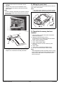
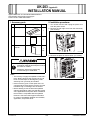
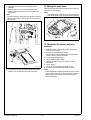
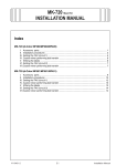
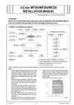
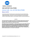
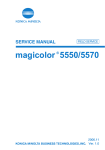
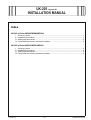
UK-203 Upgrade Kit
INSTALLATION MANUAL
Index
UK-203 (d-Color MF360/MF280/MF220)
I.
II.
III.
IV.
Accessory parts ................................................................................................................. 1
Installation procedures ....................................................................................................... 1
Affixing the panel sheet ...................................................................................................... 2
Check after the memory has been Installed ....................................................................... 2
UK-203 (d-Color MF651/MF551/MF451)
I.
II.
III.
IV.
Y110491-4
Accessory parts ................................................................................................................. 3
Installation procedures ....................................................................................................... 3
Affixing the panel sheet ...................................................................................................... 4
Check after the memory has been Installed ....................................................................... 4
E-i
Installation Manual
This page is intentionally left blank.
Installation Manual
E-ii
Y110491-4
UK-203 Upgrade Kit
INSTALLATION MANUAL
Applied Machines: d-Color MF360/MF280/MF220
COLOR MFP: 36 ppm/28 ppm/22 ppm
Product Code: A0ED
I. Accessory parts
No.
Name
II. Installation procedures
Shape
1. Turn off the machine and unplug the power cord
from the power outlet.
2. Remove the cover from the back of the machine
as shown in the illustration (four screws).
Q’ty
1. Memory
1
A0YDIXC001DA
2. Panel sheet
1
3. Installation
manual
1
set
4980IXC019DA
A0YAIXC009DA
3. Remove the plate as shown below (12 screws).
After unpacking, be sure to get rid of the
packaging materials and keep them out of
the reach of children.
Putting the head in the plastic bag
involves danger of suffocation.
Note:
• The memory is highly susceptible to static electricity. Before touching the memory be sure to
touch a metal object to discharge any static
electricity from your body and clothes.
• Never touch any pins or other parts of the circuit board when removing the memory from the
insulation bag or inserting it into the socket.
• Before starting to use the firmware updated
with this upgrade kit, make sure that the version
of the applications and printer driver installed in
the machine is compatible with the updated
firmware. Check the field support information
for version compatibility between the firmware,
application, and printer driver.
• This manual provides the illustrations of the
accessory parts and machine that may be
slightly different in shape from yours. In that
case, instead of the illustrations, use the
appearance of your machine to follow the
installation procedure. This does not cause any
significant change or problem with the procedure.
Y110491-4
A0YAIXC010DA
E-1
Installation Manual
III. Affixing the panel sheet
4. Open the tabs of the slot of the MFP board
(MFPB).
5. Making sure of the correct orientation of the
memory, insert the memory into the slot of the
MFP board.
Note:
Push the memory all the way into position until the
tabs on both sides of the slot fit into the cutouts in
the memory.
Affix the panel sheet furnished with this kit to the surface of the control panel.
Note:
• The panel sheet is affixed on customer request.
• The panel sheet must be kept by the customer.
A0YDIXC004DA
IV. Check after the memory has been
Installed
A0YDIXC005DA
1. Plug the power cord into the power outlet and
turn on the machine.
2. Display the Service Mode screen.
(For details of how to display the Service Mode
screen, see the service manual.)
3. Touch “State Confirmation.”
4. Touch “Memory/HDD State.”
5. Make sure that the volume of memory was
increased.
6. Touch “END.”
7. Touch “Exit” on the Service Mode screen.
8. Turn OFF and ON the Main Power Switch.
Note:
When displayed the Service Mode screen, be sure
to turn off the main power after exiting the Service
Mode screen and wait for 10 seconds or more
before turning on.
Tab
A0PDIXC013DA
6. To install the covers and other parts removed in
steps 2 to 3, reverse the removal procedure.
Installation Manual
E-2
Y110491-4
UK-203 Upgrade Kit
INSTALLATION MANUAL
Applied Machines: d-Color MF651/MF551/MF451
COLOR MFP: 65 ppm/55 ppm/45 ppm
Product Code: A0P0/A0P1/A0P2
I. Accessory parts
No.
Name
II. Installation procedures
Shape
1. Turn off the machine and unplug the power cord
from the power outlet.
2. Remove the rear right cover from the main body
(four screws).
Q’ty
1. Memory
1
A0YDIXC001DA
2. Panel sheet
1
3. Installation
manual
1
set
A0YAIXC006DB
4980IXC019DA
3. Remove the plate as shown below (11 screws).
After unpacking, be sure to get rid of the
packaging materials and keep them out of
the reach of children.
Putting the head in the plastic bag
involves danger of suffocation.
Note:
• The memory is highly susceptible to static electricity. Before touching the memory be sure to
touch a metal object to discharge any static
electricity from your body and clothes.
• Never touch any pins or other parts of the circuit board when removing the memory from the
insulation bag or inserting it into the socket.
• Before starting to use the firmware updated
with this upgrade kit, make sure that the version
of the applications and printer driver installed in
the machine is compatible with the updated
firmware. Check the field support information
for version compatibility between the firmware,
application, and printer driver.
Y110491-4
A0YDIXC002DA
E-3
Installation Manual
III. Affixing the panel sheet
4. Open the tabs of the slot of the MFP board
(MFPB).
5. Making sure of the correct orientation of the
memory, insert the memory into the slot of the
MFP board.
Note:
Push the memory all the way into position until the
tabs on both sides of the slot fit into the cutouts in
the memory.
Affix the panel sheet furnished with this kit to the surface of the control panel.
Note:
• The panel sheet is affixed on customer request.
• The panel sheet must be kept by the customer.
A0YDIXC004DA
IV. Check after the memory has been
Installed
A0YDIXC003DA
1. Plug the power cord into the power outlet and
turn on the machine.
2. Display the Service Mode screen.
(For details of how to display the Service Mode
screen, see the service manual.)
3. Touch “State Confirmation.”
4. Touch “Memory/HDD State.”
5. Make sure that the volume of memory was
increased.
6. Touch “END.”
7. Touch “Exit” on the Service Mode screen.
8. Turn OFF and ON the Main Power Switch.
Note:
When displayed the Service Mode screen, be sure
to turn off the main power after exiting the Service
Mode screen and wait for 10 seconds or more
before turning on.
Tab
A06HIXC003DB
6. To install the covers and other parts removed in
steps 2 to 3, reverse the removal procedure.
Installation Manual
E-4
Y110491-4