1
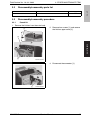
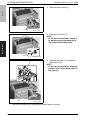
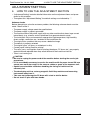
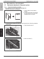
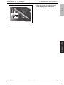
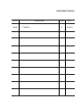
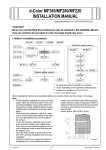
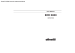
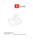
Option Printer
d-Color MF360 - MF280 - MF220
d-Color MF451
PK-517
SERVICE MANUAL
Code Y111280-7
PUBLICATION ISSUED BY:
Olivetti S.p.A.
77, Via Jervis - 10015 Ivrea (TO)
Italy
Copyright © 2009, Olivetti
All rights reserved
Field Service Ver. 1.0 Jul. 2009
PK-517
CONTENTS
PK-517
OUTLINE
2.
PERIODICAL MAINTENANCE PROCEDURE ....................................................... 3
3.
OTHER MAINTENANCE ITEM ............................................................................... 4
3.1
Items not allowed to be disassembled and adjusted ............................................ 4
3.2
Disassembly/reassembly parts list........................................................................ 5
3.3
Disassembly/reassembly procedure ..................................................................... 5
3.3.1
Punch kit ....................................................................................................... 5
ADJUSTMENT/SETTING
4.
HOW TO USE THE ADJUSTMENT SECTION ....................................................... 7
5.
MECHANICAL ADJUSTMENT ............................................................................... 8
5.1
MAINTENANCE
MAINTENANCE
OUTLINE
PRODUCT SPECIFICATIONS ................................................................................ 1
Mechanical adjustment of the punch section........................................................ 8
5.1.1
Punch hole deviation correction .................................................................... 8
i
ADJUSTMENT / SETTING
1.
ADJUSTMENT / SETTING
MAINTENANCE
OUTLINE
PK-517
Field Service Ver. 1.0 Jul. 2009
Blank Page
ii
Field Service Ver. 1.0 Jul. 2009
1. PRODUCT SPECIFICATIONS
OUTLINE
PRODUCT SPECIFICATIONS
PK-517
1.
A. Type
Name
Punch kit
Type
FS-integrated type punching operation device
Punching method
Stops and punches every paper
No. of holes
2-3 holes / 4 holes / Sweden 4 holes
Hole diameter/pitch
2 holes / I 8.0 mm / 70 mm pitch - 3 holes I 8.0 mm / 108 mm pitch
4 holes I 6.5 mm / 80 mm pitch
Sweden 4 holes / I 6.5 mm / 70 mm, 21 mm pitch
Supported mode
Punch mode
Applicable post processing
mode
Sort, group, staple
OUTLINE
B. Functions
C. Paper type
2 hole punch setting:
11 x 17, 8-1/2 x 14, 8-1/2 x 11/8-1/2 x 11S
Size
3 hole punch setting:
11 x 17, 8-1/2 x 11
4 hole punch setting:
A3, B4, A4, B5
Sweden 4 hole punch setting:
A3, B4, A4/A4S, B5
Supported paper
Plain paper, bond paper, thick paper 1/2/3 (d-Color MF360/MF280/MF220)
1/1+2/3 (d-Color MF451) Main unit specifications prioritized
Weight
60to 256 g/m2 (d-Color MF360/280/MF220) - 64 to 256 g/m2 (d-Color MF451)
Punch prohibited paper
Label paper, tab paper, transparency film, 2nd base paper, holed paper,
and the other paper that may interfere with the operation of the punch kit
or the punch blade
D. Machine specifications
Power requirements
DC 24 V (supplied from the main body d-Color MF360/MF280/MF220)
DC 5 V (supplied from the main body d-Color MF360/MF280/MF220)
Max. power consumption
30 W or less (d-Color MF360/MF280/MF220)
Dimensions
58 mm (W) x 470 mm (D) x 135 mm (H)
2.28 inch (W) x 18.50 inch (D) x 5.31 inch (H)
Weight
1.8 kg (3.97 lb)
E. Operating environment
• Conforms to the operating environment of the main body.
NOTE
• These specifications are subject to change without notice.
Y111280-7
Service Manual
1
Field Service Ver. 1.0 Jul. 2009
OUTLINE
PK-517
1. PRODUCT SPECIFICATIONS
Blank Page
2
Service Manual
Y111280-7
Field Service Ver. 1.0 Jul. 2009
2. PERIODICAL MAINTENANCE PROCEDURE
MAINTENANCE
PERIODICAL MAINTENANCE PROCEDURE
PK-517
2.
MAINTENANCE
• Periodically replaced parts are not employed.
Y111280-7
Service Manual
3
3. OTHER MAINTENANCE ITEM
3.
PK-517
3.1
Field Service Ver. 1.0 Jul. 2009
OTHER MAINTENANCE ITEM
Items not allowed to be disassembled and adjusted
A. Paint-locked screws
NOTE
• To prevent loose screws, a screw lock in blue or green series color is applied to
the screws.
• The screw lock is applied to the screws that may get loose due to the vibrations
and loads created by the use of machine or due to the vibrations created during
transportation.
• If the screw lock coated screws are loosened or removed, be sure to apply a screw
lock after the screws are tightened.
MAINTENANCE
B. Red-painted screws
NOTE
• The screws which are difficult to be adjusted in the field are painted in red in order
to prevent them from being removed by mistake.
• Do not remove or loosen any of the red-painted screws in the field. It should also
be noted that, when two or more screws are used for a single part, only one representative screw may be marked with the red paint.
C. Variable resistors on board
NOTE
• Do not turn the variable resistors on boards for which no adjusting instructions
are given in Adjustment/Setting.
D. Removal of PWBs
CAUTION
• When removing a circuit board or other electrical component, refer to “Handling of
PWBs” and follow the corresponding removal procedures.
• The removal procedures given in the following omit the removal of connectors and
screws securing the circuit board support or circuit board.
• Where it is absolutely necessary to touch the ICs and other electrical components
on the board, be sure to ground your body.
4
Service Manual
Y111280-7
Field Service Ver. 1.0 Jul. 2009
Disassembly/reassembly parts list
Section
Part name
Unit
3.3
Punch kit
PK-517
3.2
3. OTHER MAINTENANCE ITEM
Ref. page
P.5
Disassembly/reassembly procedure
3.3.1
Punch kit
1. Remove the finisher from the main body.
2. Remove four screws [1], and remove
the finisher upper cover [2].
[1]
MAINTENANCE
[2]
[1]
A0HRF2C503DA
3. Disconnect the connector [1].
[1]
Y111280-7
A10EF2C504DA
Service Manual
5
3. OTHER MAINTENANCE ITEM
Field Service Ver. 1.0 Jul. 2009
PK-517
4. Remove three screws [1].
[1]
A10EF2C505DA
[1]
MAINTENANCE
5. Remove two screws [1].
NOTE
• At the time of installation, secure it
by adjusting the plate dowel [2] to
the center of the stamp mark.
[2]
A10EF2C506DA
6. Remove the plate [1], and remove
the punch kit [2].
NOTE
• At the time of installation, align the
position of the three dowel holes of
the plate [3].
[1]
[3]
[2]
A10EF2C507DA
7. Reinstall the above parts following the removal steps in reverse.
6
Service Manual
Y111280-7
Field Service Ver. 1.0 Jul. 2009
4. HOW TO USE THE ADJUSTMENT SECTION
ADJUSTMENT/SETTING
HOW TO USE THE ADJUSTMENT SECTION
PK-517
4.
• “Adjustment/Setting” contains detailed information on the adjustment items and procedures for this machine.
• Throughout this “Adjustment/Setting,” the default settings are indicated by “ ”.
Advance checks
Before attempting to solve the customer problem, the following advance checks must be
made. Check to see if:
•
•
•
•
•
•
CAUTION
Be sure to unplug the power cord of the machine before starting the service job
procedures.
If it is unavoidably necessary to service the machine with its power turned ON, use
utmost care not to be caught in the scanner cables or gears of the exposure unit.
Special care should be used when handling the fusing unit which can be
extremely hot.
The developing unit has a strong magnetic field. Keep watches and measuring
instruments away from it.
Take care not to damage the PC drum with a tool or similar device.
Do not touch IC pins with bare hands.
Y111280-7
Service Manual
7
ADJUSTMENT / SETTING
• The power supply voltage meets the specifications.
• The power supply is properly grounded.
• The machine shares the power supply with any other machine that draws large current
intermittently (e.g., elevator and air conditioner that generate electric noise).
• The installation site is environmentally appropriate: high temperature, high humidity,
direct sunlight, ventilation, etc.; levelness of the installation site.
• The original has a problem that may cause a defective image.
• The density is properly selected.
• The original glass, slit glass, or related part is dirty.
• Correct paper is being used for printing.
• The units, parts, and supplies used for printing (developer, PC drum, etc.) are properly
replenished and replaced when they reach the end of their useful service life.
• Toner is not running out.
5. MECHANICAL ADJUSTMENT
5.
PK-517
5.1
5.1.1
Field Service Ver. 1.0 Jul. 2009
MECHANICAL ADJUSTMENT
Mechanical adjustment of the punch section
Punch hole deviation correction
• This adjustment must be made in the following case:
The punch holes are on a slanted line.
1. Set the mode to Punch mode for
printing.
2. Hold the output paper half and check
the displacement of the punch hole.
Standard value: 0 ± 2.0 mm
A10EF2C503DA
3. In case the figure exceeds the above mentioned standard value, follow the procedures
shown below.
4. Open the upper cover [1].
ADJUSTMENT / SETTING
[1]
A10EF2C502DA
• Loosen two screws [1].
[1]
8
A10EF2C500DA
Service Manual
Y111280-7
5. MECHANICAL ADJUSTMENT
• Move the punch unit forward or backward for adjustment referring the
mark-off line [1].
[1]
PK-517
Field Service Ver. 1.0 Jul. 2009
ADJUSTMENT / SETTING
A10EF2C501DA
Y111280-7
Service Manual
9
Field Service Ver. 1.0 Jul. 2009
ADJUSTMENT / SETTING
PK-517
5. MECHANICAL ADJUSTMENT
Blank Page
10
Service Manual
Y111280-7
UPDATING STATUS
DATE
09/2009
UPDATED PAGES
1ST EDITION
PAGES
15
CODE
Y111280-7