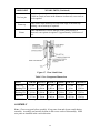
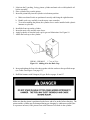
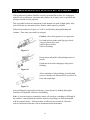
1
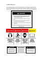
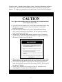
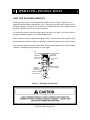
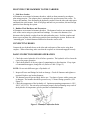
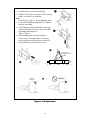
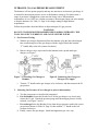
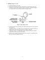
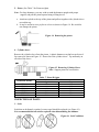
HUSKIE
HYDRAULIC
HAMMERS
SERVICE
MANUAL
HH100
HH150-2
HH300-2
HH500-2
HH750-2
HH1000-2
2
CONTENTS
1.
Safety Information
Page 4
Safety Decals
Safety Symbols
2.
Operating Instructions
Page 7
How the Hammer Operates
Mounting the Hammer to Carrier
Connecting Hoses
Daily Inspection before Operation
Initial Startup, Hammer Break-in
General Operation Instructions
Cold Weather Startup and Operation
Underwater Operation
Storage
Tool Replacement
3.
Maintenance
Page 13
Hydraulic Oil
Checking Condition of Hydraulic Oil
Fasteners
Greasing Requirements
Nitrogen (N2) Gas Pressure Adjustment
Oil Leakage Inspection
Gas Leakage Inspection
4.
Disassembly and Assembly
Page 19
Disassembly
Inspection of Parts
Component Wear Limits
Assembly
5.
Specifications
Page 26
6.
Refinishing of Pistons and Cylinders
Page 27
7.
Troubleshooting Diagnosis
Page 28
8.
Warranty Guidelines
Page 29
9.
Parts List and Illustrations
Page 33
1. SAFETY INFORMATION
•
•
•
•
•
•
•
•
•
•
•
•
•
•
•
•
•
•
•
•
•
Always read the information in this manual before operating the hammer. Failure to
do so can result in personal injury or damage to the equipment.
Check that all safety decals attached to the hammer and carrier are legible. Replace
worn or illegible decals.
Do not use drugs or alcoholic beverages that impair alertness or coordination while
operating the carrier or hammer. An operator taking prescription drugs must obtain
professional medical advice to determine if he/she can safely operate the carrier and
hammer.
Work at a slow pace when learning to operate the hammer.
Operator training must consist of a demonstration and verbal instruction.
New operators must start in an area free of bystanders. He/she must become familiar
with all carrier controls before operating the hammer.
Be aware of any prohibited uses in work areas. (Excessive slopes, poor or dangerous
terrain conditions and utility hazards.)
Operate the carrier or hammer from the operator’s seat ONLY. Make sure the seat is
fastened securely before activating controls.
Keep hands and feet on the controls at all times while the hammer is operating.
Always operate the carrier with the outriggers firmly positioned on the surface.
Make sure all controls (levers and pedals) are in NEUTRAL before starting the
carrier.
NEVER leave the carrier with the engine running. ALWAYS ENGAGE THE
PARKING BRAKE.
Make certain there are no persons within the arc determined by the movement of
stabilizers, front bucket or backhoe boom with the hammer at full extension.
Never operate with any person near the hammer or between the hammer and the
operator.
Replace all faulty or leaking hydraulic hoses or fittings before operation.
Travel with the hammer in the full tuck (transport) position only.
Never operate the hammer with the tool retaining pin removed.
Wear safety goggles, hearing protection and hardhat while operating the hammer.
Before leaving the operator’s seat, always lower the carrier boom or bucket arms.
Stop the engine before attempting to make any repairs or adjustments to either the
carrier or the hammer.
ALWAYS OBSERVE ALL SAFETY INSTRUCTIONS APPLICABLE TO
YOUR CARRIER.
4
SAFETY DECALS
The decals shown below are attached to the hammer when shipped from the factory.
Read and understand them before operating the hammer. Replace any decal that has
become worn, damaged or illegible. Decals can be ordered through parts department.
CAUTION
DANGER
This symbol may appear on
the hammer or in the text of
this manual. It is used to alert
the operator of an action that
can place him/her or others in
a life threatening situation.
This symbol appears in the
text of this manual to identify
an action or condition that
can result in damage to the
hammer or other equipment.
5
The notice below is included in the shipping carton. It contains information relating to
operator safety. Read and understand this notice before unpacking or operating the
hammer. We suggest you retain this notice and include it in your local safety program.
CAUTION
Never operate the hammer unless the following Safety Instructions have
been read and understood.
•
•
•
•
•
•
Projectiles from the hammer, tool, rock or other broken material may enter
the operator’s area and cause serious or fatal injury. Use personal
protection equipment.
Projectiles from the hammer, tool, rock or other broken material may
cause serious or fatal injury to bystanders. Do not operate the hammer
when bystanders are in the area.
In some cases, the hammer may enter the operator’s area if a bracket or
cylinder breaks. Make sure appropriate shields are used when operating
the hammer with this type of equipment.
Shown above is a copy of a decal that must be installed on a surface of the
hammer that faces the operator and on the carrier operator’s control area.
Never operate the hammer if these decals are missing. Decals must be
inspected periodically to ensure that all wording is legible. Decals should
be replaced if illegible.
Decals can be obtained at no charge from your IPC Distributor or by
contacting IPC’s Customer Service Department.
6
2. OPERATING INSTRUCTIONS
HOW THE HAMMER OPERATES
The main valve (Figure 1) for the hammer is built into the cylinder. Hydraulic oil is
supplied into the hammer through this valve. During the upward stroke, the pressure in
the upper chamber is released via the main valve and through the outlet. High pressure in
the lower chamber then forces the piston upward.
As soon as the piston reaches the upper end of the stroke, the main valve directs flow to
the upper chamber causing it to become high pressure.
Since surface A is greater than surface B, the piston is driven downward with the help of
the accumulated energy from the gas chamber, creating the impact stroke of the hammer.
At the point of impact, the main valve shifts, releasing the high pressure from the upper
chamber, enabling the upward stroke to occur again.
GAS
CHAMBER
UPPER CHAMBER
(VARIABLE
PRESSURE)
PRESSURE
RECIEVING
SURFACE A
BUILT-IN MAIN
VALVE
MIDDLE CHAMBER
(LOW PRESSURE)
PRESSURE
RECIEVING
SURFACE B
LOWER CHAMBER
(HIGH PRESSURE)
TOOL
Figure 1. Principles of Operation.
(Refer to Table 10 page 26.)
7
MOUNTING THE HAMMER TO THE CARRIER
1. Skid Steer Loader
All hammers are mounted to hammer brackets, which are then mounted to an adapter
plate using two pins. The adapter plate is mounted to the quick mount of the carrier. To
remove the hammer, first disconnect the hydraulic couplers from the inlet and outlet ports
and detach the quick mount. Seal off all plugs and hoses to prevent dust, dirt and foreign
particles from entering the system.
2. Rubber-Tired Backhoes and Excavators
All hammers are mounted to hammer brackets. The hammer brackets are mounted to the
stick of the carrier using two pins and four bushings. To remove the hammer, first
disconnect the hydraulic couplers from the inlet and outlet ports. Seal the couplers and
hoses to prevent dust, dirt, and foreign particles from entering the system. Remove the
“mounting pins” to detach hammer and bracket from the carrier stick.
CONNECTING HOSES
Connect the two hydraulic hoses to the inlet and outlet ports of the carrier using hose
couplers. When connecting, make sure that the couplers are clean and engaged securely.
DAILY INSPECTION BEFORE OPERATION
1. Check the carrier hydraulic oil level before operation. The hydraulic oil level must be
correct for proper operation.
2. Check the hydraulic oil for any signs of contamination or discoloration. If any signs
of contamination appear, change the oil. (Refer to Table 2, Page 13)
NOTE: Do not mix different types of hydraulic oil.
3. Inspect all hoses and fittings for leaks or damage. Check all fasteners and tighten as
required. Replace any broken fasteners.
4. The hammer must be greased daily before use. Ten shots of grease with a grease gun
is adequate. The hammer should be greased every 2-3 hours during operation. (See
Figure 2)
5. Check the temperature of the hydraulic oil. Optimum operating temperature is 120°/
200° F (49°/93°C). The unit may not function properly and seal damage may result if
the hydraulic oil temperature goes beyond the recommended range.
Figure 2. Hammer Lubrication Point
8
INITIAL STARTUP, HAMMER BREAK-IN
New or rebuilt hammers require 20-40 minutes of operation at half the rated speed as a
break-in period. This allows for proper lubrication of all moving parts and for all sliding
surfaces to mate properly.
GENERAL OPERATING INSTRUCTIONS
1. Never apply the tool with a side load. The tool must always be pressed firmly
against, and be perpendicular to the material to be broken. Failure to do so can cause
tool or seal failure.
2. Impact action must be stopped immediately when the object has been broken.
3. Do not pry with the tool. This may cause the tool to break or cause abnormal wear to
the tool bushings.
4. Avoid continuous impact on the same area for more than one minute. Continuous
impact may cause a rapid increase in oil temperature and improper hammer operation.
5. Break large objects from the outside edges and work inward.
6. Do not submerge the hammer in water. The hammer is not watertight, and damage
can occur if used in this manner. Consult your dealer for underwater applications
(Ref. Figure 3.)
7. Do not use the hammer to move very large or heavy broken objects. This can cause
damage to the hammer and carrier.
8. Do not use the hammer as a lifting device.
9. Do not operate the hammer when boom cylinders are at their extreme ends. This may
cause damage to the cylinders.
10. Stop operation immediately if hoses vibrate abnormally or impact energy is
dramatically reduced. Consult Section 7. “Troubleshooting Diagnosis” for additional
information.
COLD WEATHER STARTUP AND OPERATION
Note: Internal parts of the hammer will be damaged if proper warm-up procedures are
not applied in cold weather.
1. Warm the hydraulic system of the carrier before starting the hammer. Circulate the
oil in carrier system until it is warm to the touch or approximately 60°F (15°C)
2. With engine at half throttle, activate the hammer for 5 seconds and stop for 15
seconds. Repeat cycle for 2 to 3 minutes.
9
UNDERWATER OPERATION
Operation of hydraulic hammers under water requires proper preparation to prevent
internal damage to hammer parts and carrier hydraulic system.
1. To prepare the hammer for underwater operation you will need
an external compressed air supply.
a. For HH100 through HH500-2, 5 –10 CFM at 50 to 90 psi is
adequate.
b. For HH750-2 and HH1000-2, 20 to 50 CFM is required.
2. Connect air supply line to front cap threaded port (remove plug
P/N 3Z01-FP0038 as shown.) Thread is 3/8 inch pipe tapered.
3. Set pressure regulator to 50 – 90 psi.
4. Maintain air supply to hammer at all times when operating
under water
PRESSURE REGULATOR
Figure 3. Air Compressor Supply
10
STORAGE
1. Short Term
If the hammer will not be used for periods of one week or more, the tool should be
removed from the hammer and grease must be applied to the piston bottom. The hammer
should be stored indoors standing vertically in the working position.
2. Long Term
For storage of more than 2 - 3 weeks or where condensation or corrosion is prevalent
(salt-water areas) note the following instructions. Remove and clean the tool. Flush the
front cap with clean solvent or hydraulic oil. Coat the exposed portion of the piston with
grease, apply grease to the tool and re-install. Store the hammer vertically and away
from standing moisture. To start the hammer after long-term storage, remove the tool
and inspect the exposed portion of the piston for corrosion. If corrosion is found do not
use the hammer until the defective piston has been repaired or replaced.
TOOL REPLACEMENT
Table 1. Standard Tool Weights
HAMMER MODEL
HH100
HH150-2
HH300-2
HH500-2
HH750-2
HH1000-2
WEIGHTS
kg
5
7
14
15
23
37
lbs.
12
15
30
32
51
82
11
•
•
Carefully drive out the tool spring pin.
Push the tool set pin up and out of the front cap
using a screwdriver or round bar.
Note:
Check Table 1, Page 11, before handling tools.
• For models HH100 through HH750-2, manual
removal is possible.
•
For the hammer models HH1000-2 and larger
use hoist and sling as shown. Check for sling
load rating and compare to
Table 1, Page 11.
• When installing the tool in the hammer,
reverse steps 1 through 4 above. Note that
tool spring pin must be inserted with the slot
or open side away from the tool set pin.
4
SLING ANGLES
NOT SMALLER THAN:
o
60
1/3
Figure 4. Tool Replacement
12
1/3
1/3
3. MAINTENANCE
HYDRAULIC OIL
Note: It is not recommended to mix types of hydraulic oils. Check carriers hydraulic oil
recommendations before adding hydraulic oil.
1. Check the oil level, oil filter condition and oil cooler in the carrier periodically.
2. Replace the hydraulic oil every 600 hours and the filter every 100 hours, or according
to carrier recommendations.
3. Always be aware of any abnormalities in the operation of the hammer such as
changes to hammer blow speed, impact force or oil temperature. The oil temperature
should not exceed 180°F (80°C).
4. Check the condition of the hydraulic oil as specified in Table 2.
CHECKING CONDITION OF HYDRAULIC OIL
Note: Refer to carrier service manual for proper class and type of hydraulic oil.
Hydraulic oil must be changed more frequently than the carrier instruction manual
recommends. This is because hammer operation requires more oil circulation than
normal operation. Oil condition can be visually checked as specified in Table 2.
Table 2. Hydraulic Oil Conditions
COLOR
CONDITION
Transparent and no color change
Good
Transparent but too bright
Oil Mixed
Milky white
Air and / or water mixed
Dark and dirty with odor
Deteriorated
Transparent but with black spots
Foreign particles mixed
Bubbly
Grease mixed
13
FASTENERS
Inspect all bolts and nuts for tightness. Tighten as required. (Refer to Table 4, Page 15)
Replace all missing or damaged fasteners before operating the hammer.
Fastener bolt and nut sizes are listed in Table 3. These are wrench sizes (distance across
flats.)
Table 3. Bolt Sizes
GAS VALVE
HAMMER
NIPPLES
(mm.)
BRACKET
BOLTS
(mm.)
SIDE ROD
BACK NUT
(mm.)
SIDE ROD
ALLEN
HEAD
(mm.)
LIFTING
EYES
(inches)
CAP
(inches)
BODY
(mm.)
HH100
19
28
NA
*14
½”-13pt
1” Crow
Foot
36
HH150-2
30
36
32
NA
½”-13pt
1” Crow
Foot
36
HH300-2
30
36
41
NA
½”-13pt
1” Crow
Foot
36
HH500-2
30
36
41
14
¾”-10pt
1” Crow
Foot
36
HH750-2
30
36
46
14
¾”-10pt
1” Crow
Foot
36
HH1000-2
36
50
46
17
¾”-10pt
1” Crow
Foot
36
* Allen wrench size for the front and back cap bolts.
14
Table 4. Tightening Torque Requirements (Ft. lbs.)
HH100
HH150-2
HH300-2
HH500-2
HH750-2
HH1000-2
Side Rod
NA
400 ±35
550 ±35
NA
NA
NA
Side Rod Back Nut
NA
NA
NA
730 ±35
730 ±35
770 ±35
Front Cap Set Bolt
175 ±35
NA
NA
NA
NA
NA
Back Cap Set Bolt
175 ±35
NA
NA
NA
NA
NA
Bracket Bolt
150 ±35
260 ±35
260 ±35
260 ±35
260 ±35
400 ±35
5
1
1
3
7
1
3
5
3
1
4
3
Figure 5. Tightening Sequence
4
2
4
2
6
6
4
2
8
2
5
GREASING REQUIREMENTS
The hammer should be greased each startup and after every 2-3 hours of operation. The
grease nipple is located at the front cap as shown in Figure 6. Approximately 10 shots in
the front cap are recommended when the tool is at the upper limit of travel.
Figure 6. Grease Fitting
Figure 6.
15
NITROGEN (N2) GAS PRESSURE ADJUSTMENT
The hammer will not operate properly and may not start due to an incorrect gas charge. It
is normal for the nitrogen pressure to rise as the hammer warms up. For that reason, a
range of pressures is stamped on a plate near the charge valve. When ambient
temperatures of over 1000F are a routine occurrence, the nitrogen charge can raise enough
to stop the hammer. See Table 11, Page 26 for charge settings at high ambient
temperatures.
Follow the procedure described below to adjust nitrogen (N2) gas pressure.
WARNING!
DO NOT STAND NEAR THE HAMMER WHEN ADDING NITROGEN. THE
TOOL MAY EJECT SUDDENLY AND CAUSE SEVERE INJURY.
1. Gas Pressure Testing.
a. With the gas charger disconnected from the hammer, plug the inlet (the nitrogen
hose connection port) of the gas charger with the cap provided, then turn the
“T” handle fully to the left (counter clockwise.)
b. Remove the gas valve cap located on the hammer back cap and attach gas
charger, see Figure 7.
Figure 7. Connecting Gas Charger to
Hammer
Figure 8. Connecting Gas Charger to
Nitrogen (N2) Supply
c. Turn the “T” handle on the gas charger valve clockwise, and then measure the N2
gas pressure.
2.
Releasing Gas Pressure (if over charged or prior to disassembly.)
a. Test the gas pressure as described in paragraph 1.
b. For disassembly loosen the bleeder screw on the gas charger very slowly and
release the N2 gas. Watch the pressure gauge until the nitrogen pressure is fully
released; (see Figure 7 and 8.)
c. If overcharged close the Bleeder Screw when the gas pressure reaches the correct
gas pressure shown on Table 10, Page 26, then turn the “T” handle to the left
(counter clockwise).
d. Finally, remove the gas charger. Install and tighten the gas valve cap.
16
3. Refilling Nitrogen (N2) Gas
a. Perform paragraph 2 procedure.
b. Remove the cap on the gas charger, nitrogen hose connection port. See Fig 9.
c. Attach the N2 gas pressure regulator to the gas container. Connect the nitrogen
(N2) Supply tank to the gas charger with the charging kit hose.
Figure 9. Gas Charger Valve
d. Open the main gas valve on the N2 gas container and regulate the N2 gas pressure
(see Figure 8.)
e. Turn the gas charger “T” handle clockwise and adjust N2 gas pressure in the gas
chamber to the correct gas pressure shown on Table 10, Page 26.
f. Turn the gas charger “T” handle fully counter clockwise and remove the hose.
Attach the cap to the gas inlet of the charger.
g. Remove the gas charger and attach the gas valve cap and “O” ring firmly to the
gas valve nut on the hammer back cap.
17
OIL LEAKAGE INSPECTION
Check for oil leakage at the points shown in Table 5. It is not unusual to have a small
amount of oil leakage along the tool or cylinder, (refer to Figure 10, Page 18)
Table 5. Diagnosis of Oil Leakage
LEAK LOCATION
POSSIBLE CAUSE
REMEDY
Between front cap
and tool (E)
Damaged or worn
U-packing
Replace seal kit
Between cylinder and
nipple (F)
Loose nipple or damaged
O-ring or nipple
Tighten or replace nipple,
and / or O-ring
Between cylinder and
back cap (G)
Damaged U-packing or
main
Valve outer sleeve O-ring,
or
Back cap O-ring
Replace seal kit.
Plug ports (H)
Plugs loosen
Remove plugs and reinstall
with sealant
F
H
E
G
Figure 10.
18
GAS LEAKAGE INSPECTION
Gas leakage can be easily detected using soapy water (refer to Table 6 and Figure 11.)
Table 6. Diagnosis of Gas Leakage
LEAK LOCATION
Gas valve assembly (A) or
Between gas valve assembly
and back cap (B)
Between back cap and
cylinder (C)
POSSIBLE CAUSE
REMEDY
Defective O-ring,
damaged
Spring or gas valve
Replace gas valve
assembly
Defective back cap O-ring
Replace back cap O-ring
Figure 11
4. DISASSEMBLY AND ASSEMBLY
19
DISASSEMBLY
1. Tool
Refer to tool replacement procedures (Figure 4, Page 12).
2. Back cap
Support the cylinder (Figure 12). Loosen and remove four side rods and washers,
then remove the back cap.
3. Front cap (See Table 3 page 14 for eyebolt sizes)
Install an eyebolt and suspend the front cap as shown in Figure 12. Pull out the front
cap, being careful not to damage the piston.
Figure 12. Connecting Hoist to Front Cap.
4. Main valve
Attach an eyebolt to outer sleeve and remove it by pulling the eyebolt. (Figure 13.)
Remove the main valve. The inner sleeve cannot be removed, it is press fitted and
requires a special tool. Contact the factory for further details.
Figure 13. Removing the Main Valve
20
5. Piston (See Table 7 for Piston weights)
Note: For large hammers, you may wish to stand the hammer upright with proper
support, and pull the piston upward using a lifting device.
a. Attach an eyebolt to the top of the piston and pull out together with cylinder sleeve
toward the top.
b. It may be useful to use a pry bar as a lever as shown in Figure 14. Be careful to
not damage the piston.
Figure 14. Removing the piston.
6. Cylinder sleeve
Remove the cylinder sleeve from the piston. A plastic hammer or nylon bar can be used
for removal as shown in Figure 15. Do not force the cylinder sleeve. Tap uniformly on
all sides of the sleeve.
Figure 15. Removing Cylinder Sleeve
Note: Support piston on wood blocks.
Table. 7. Piston Weights
HAMMER MODEL
HH100
HH150-2
HH300-2
HH500-2
HH750-2
HH1000-2
WEIGHTS
kg
5.8
6.0
9.7
10.0
17.1
25.4
lbs.
12.7
13.2
21.3
22.0
37.6
55.9
INSPECTION OF PARTS
1. Seals
Seals that are deformed, scratched, worn or aged should be replaced (see Figure 16).
It is recommended that all seals be replaced when disassembling the hammer.
Figure 16. Seal Conditions
21
2. Moving parts
Check for any scratches or damage on the surface of the piston, cylinder sleeves, main
valve and bottom part of the piston where it strikes the tool. Significantly damaged or
scratched parts must be replaced.
3. Front cap
a. Deformed or worn shank bushings or front cap bushings must be replaced, see
Table 8 page 23.
b. A severely worn or damaged tool set pin must be replaced.
4. Replacing the front cap bushing
a. Measure shank and front cap bushings and refer to Table 8 page 23 and Table 9
page 24.
b. Remove bushing set pin and bushing spring pin using a hammer and drive pin.
c. The front cap bushing must be torch cut at three locations (at three 120° grooves)
if it is the only bushing to be replaced. Avoid cutting into the front cap itself,
press out the front cap bushing only if both bushings need replacement.
d. Any scratches in the front cap must be smoothed after bushing removal.
e. Install the new front cap bushing in the correct direction with part numbers on the
bushing facing the installer (away from the hammer.) Because the bushings are a
press, or interference fit, heating of the front cap and cooling of the bushing will
help installation.
f. Insert the bushing set pin and the bushing spring pin.
BE CAREFUL OF HOT SURFACE. USE GLOVES TO PROTECT
AGAINST BURNS AND POSSIBLE SHARP EDGES.
5. Replacing the shank bushing
Note: Replacement of the front cap bushing is highly recommended when replacing the
shank bushing, as the front cap bushing must be removed to replace the shank
bushing.
a. Measure the shank and front cap bushing; refer to Table 8 page 23 and Table 9
page 24.
b. Remove bushing spring pin and bushing set pin for shank bushing on the front cap
using a punch and hammer.
c. Press out shank bushing from the cylinder side together with front cap bushing
using a round bar. If the shank bushing is too tight, cutting it with a torch may be
required. A worn moil or chisel can be machined flat at the working end to serve
as a press mandrel to remove the bushing.
22
d. Any scratches on the front cap during the cutting operation must be smoothed out
using a hand grinder.
e. Install a new shank bushing after greasing. As bushings are a press, or
interference fit, heating of the front cap or cooling of the bushing will ease
installation of the bushing.
f. Install the bushing set pin and the bushing spring pin.
6. Refinishing surface scratches (see Section 6, Page 27)
a. Cylinder and Cylinder Sleeve
Scratches on the inside surface of the cylinder should be smoothed using a flap wheel
with 240 grit and finish with 360 grit.
b. Piston
Grind off any scratches on the outside surface using a flap wheel with 240 grit and
finish with 360 grit. When polishing the piston or the cylinder bore, it is not necessary
to completely remove scratches (only the sharp edges) as this may remove excess
material. (Figures 19, 20 and 21, Page 27)
c. Main Valve and Sleeves
Main valve and sleeves cannot be polished. Replace if these parts do not slide freely
by finger pressure.
COMPONENT WEAR LIMITS
Parts are to be replaced if they are not within the wear parameters. See Table 8 and
Figure 17, for new dimensions see Table 9 page 24.
Table 8. Component Wear Limits
COMPONENT
Front cap
bushing
WEAR LIMITS
When the clearance between the tool and the front cap bushing
exceeds .200 in. (5mm), a new front cap bushing is required.
(Approximately 500 hours of use).
Shank bushing
When the clearance between the tool and the shank bushing exceeds
.160 in. (4mm), a new shank bushing is required. (Approximately
700 hours of use).
Tool
If .120 in. (3mm) of wear in the diameter is observed, a new tool is
required. (Approximately 500 hours of use). Keep tool sharp.
23
COMPONENT
WEAR LIMITS (Continued)
Tool set pin
If .080 in. (2mm) of wear in the diameter is observed, a new tool set
pin is required.
Front cap
Piston
If the corner of the front cap is worn to the edge of the front cap
bushing, a new front cap is required.
When indentation or serious damage on the piston surface is
observed, a new piston is required. (Approximately 2,000 hours of
use).
Figure 17. Wear Limit Points
Table 9. New Component Dimensions
PART
Front Cap
Bushing I.D.
Shank
Bushing I.D.
*HH100 HH150-2 HH300-2 HH500-2 HH750-2 HH1000-2
41. mm.
51. mm.
61. mm.
66. mm.
76. mm.
91. mm.
1.614 in. 2.008 in. 2.402 in. 2.598 in.
3.0 in.
3.583 in.
41. mm.
51. mm.
61. mm.
66. mm.
76. mm.
91. mm.
1.614 in. 2.008 in. 2.402 in. 2.598 in.
3.0 in.
3.583 in.
40. mm.
50. mm.
60. mm.
65. mm.
75. mm.
90. mm.
Tool O.D.
1.575 in. 1.768 in. 2.362 in. 2.559 in. 2.953 in.
3.543 in.
* HH100 does not have replaceable bushings. Measurements refer to the front cap itself.
ASSEMBLY
Note: Clean every part before assembly. Keep parts clean and do not scratch during
assembly. Assembly can basically be done in the reverse order of disassembly. Make
sure parts are installed in the correct direction.
24
1. Lubricate the U-packing, O-ring, piston, cylinder and main valve with hydraulic oil
before assembly.
2. Place cylinder sleeve on the piston.
3. Insert the piston fully into the cylinder to its bottom position.
a. Make sure that all seals are positioned correctly and facing the right direction.
b. Handle seals very carefully in order not to cause scratches.
c. To avoid scratching the piston, the cylinder sleeve can be installed with a plastic
hammer or nylon bar.
4.
5.
6.
7.
Install the front cap on the cylinder.
Insert the main valve and the outer sleeve.
Apply hydraulic oil into the back cap for gas seal lubrication. See Figure 18.
Attach the back cap to the cylinder.
HH100 – HH1000-2 1.7 oz. or 50 cc
Figure 18. Adding oil to the Back Cap.
8. Insert and tighten the four side rods together with the washer to the specified torque
(see Table 4 and Figure 5 on page 15.)
9. Refill the hammer with Nitrogen (N2) gas. Refer to pages 16 and 17.
Make sure that the piston is positioned at the lower end of its stroke before charging. The
piston and the cylinder may be damaged during gas charging by sudden movement (due
to a pressure increase) if the piston is not at the bottom of its stroke in the cylinder.
25
5.
SPECIFICATIONS
Table 10. Specifications by Model
ITEM
Impact
Energy Class
Adjustable
Blows Per
Minute
Required Oil
Flow
UNIT
ft-lbs.
kg-m
HH100
100
14
bpm
700-1300
gpm
l/min
Operating
Pressure
psi
bar
Nitrogen Gas
Pressure
Total Weight
with Tool
Total Length
Tool Diameter
Applicable
Carrier
HH150-2
200
28
HH300-2
350
49
HH500-2
575
81
HH750-2
825
116
HH1000-2
1200
168
520-1170
590-1200
510-1,180
600-1080
500-860
5-12
20-45
1,0141,867
70-129
190-210
13-14
340
154
50
1,270
2.0
50
8-16
30-60
1,2941,867
89-129
190-210
13-14
520
236
52
1,321
2.4
60
9-18
35-70
1,4411,867
99-129
160-185
11-13
550
250
54
1,372
2.6
65
13-24
50-90
1,4412,161
99-149
190-210
13-14
800
363
64
1,626
3.0
75
16-35
60-130
psi
bar
lbs.
kg
inch
mm
inch
mm
4-7
20-45
1,0002,275
69-160
140-160
10-11
165
154
35
889
1.6
40
Tons
.75-2.25
1.25 – 3.25
2.25 - 6
2.75 - 7
3.35 – 8
1,720-2,587
119-178
190-210
13-14
1,100
500
73
1,854
3.5
90
3.5 - 12
Remarks:
•
•
•
The hammer is to be used within the specified oil pressure, oil flow and gas pressure parameters.
The carrier hydraulic system relief pressure is to be set at 600 to 800 psi above the hammer
“Operating Pressure” measured at the hose end of the carrier (pressure hose) when disconnected
from the hammer.
The nitrogen charge in a hammer is directly related to the operating pressure of the circuit
powering it. An increase of 10% in gas charge will cause a 10% rise in hammer operating
pressure. This is prevalent in hammers if gas pressure has been set or checked on a cool morning
(600F) and then run in increasingly higher ambient temperatures up to and over 1000F. This
increase in ambient temperature can cause the carrier operating pressure to rise past its relief
setting, stalling the hammer.
Table 11. Recommended Gas Pressure Based Upon Ambient Temperature*
800F
900F
1000F
1100F
1200F
Hammer Model Standard Pressure
HH100
140 – 160 psi
160 psi 150 psi 140 psi 130 psi 120 psi
HH150-2
190 – 210 psi
210 psi 200 psi 190 psi 180 psi 170 psi
HH300-2
190 – 210 psi
210 psi 200 psi 190 psi 180 psi 170 psi
HH500-2
160 – 185 psi
185 psi 175 psi 160 psi 150 psi 140 psi
HH750-2
190 – 210 psi
210 psi 200 psi 190 psi 180 psi 170 psi
HH1000-2
190 – 210 psi
210 psi 200 psi 190 psi 180 psi 170 psi
* Gas pressure should be set bearing in mind the possible high ambient temperature
potential for that day’s work. While unlikely, a setting that will run well on a hot day
may run erratically until the hammer warms up thoroughly. Please contact IPC
Industries, Inc. if you have any questions.
26
6.
REFINISHING OF PISTONS & CYLINDERS
If the pistons and cylinders should be scored or scratched due to dirty oil, or improper
hydraulic oil specifications, the piston and cylinder can, in many cases, be polished and
salvaged, instead of being replaced.
This is possible because the components in this hammer are made of high quality alloy
steel and do not use chromium surface finishes which cannot be polished.
Follow the procedures in Figures 19, 20 & 21 and finish by thorough flushing and
cleaning. These parts can usually be salvaged.
Caution: Wear safety glasses for eye protection
Use hand held air grinder with flap type wheels.
Two grit wheels were used:
#240 for Heavy Polish.
#360 for Finishing.
Figure 19.
Rotate piston and polish with brushing motion of
grinder.
Polish total area before changing to fine grit for
finishing.
Figure 20.
After completion of fine polishing, clean labyrinth
grooves carefully with fine needle file to remove all
burrs and rough edges.
Figure 21.
After polishing all rough surfaces and edges, clean all parts by flushing thoroughly.
Lubricate with hydraulic oil before reassembling.
Note: It is not necessary to completely remove all scoring or scratching to full depth of
the scratches. Instead polish the surfaces until any raised edges are flush and smooth
with the original surface. If this procedure is followed excess material will not be
removed and normal tolerances can be maintained inside the hammer.
27
7. TROUBLESHOOTING DIAGNOSIS
Table 12. Troubleshooting
SYMPTOM
POSSIBLE CAUSE
Hammer
Couplers are not engaged
does not run
Relief valve set incorrectly
Hesitation or
erratic
operation
Slow impact
speed
Low impact
power
Malfunction of the hydraulic pump
Nitrogen gas pressure is too high
Main valve is damaged
Piston is damaged
Couplers are not fully engaged
Relief valve set incorrectly
Malfunction of the hydraulic pump
Oil temperature is too high
(exceeds 180°F or 80°C)
Main valve is damaged
Decreased oil flow
Auto shut-off in operation, tool is
suspended
Excessive bushing wear
Piston is damaged
Nitrogen pressure is too high
Hydraulic oil leakage into the gas
chamber
Malfunction of the hydraulic pump
Deteriorated or contaminated oil
Nitrogen gas pressure is low
Relief valve set incorrectly
Malfunction of the hydraulic pump
28
REMEDY
Connect couplers securely
Adjust main and secondary relief
valve
Repair pump
Adjust gas pressure
Replace main valve
Repair or replace piston
Connect couplers securely
Adjust main and secondary relief
valve
Repair pump
Check oil cooler
Replace damaged main valve
Avoid simultaneous axis movement
Apply proper down force
Replace worn bushings
Repair or replace piston
Adjust gas pressure
Replace seal kit
Repair pump
Change oil
Adjust gas pressure
Adjust main and secondary relief
valve
Repair pump
8. WARRANTY GUIDE LINES
Time based on total man-hours.
Seal kit installation (Includes testing, complete disassembly, cleaning and re-assembly)
HH100 - HH1000 = 4 hours
HH1500 - HH2000 = 6hours
HH3600 - HH4500 = 7hours
HH5800 – HH8000 = 8hours
Front cap bushing (Includes removal and re-installation, hammer disassembly not
required)
HH150 - HH1000 = ½ hour
HH1500 - HH8000 = 1 hour
Shank bushing (Includes complete disassembly, removal of both bushing and reassembly)
HH150 - HH1000 = 3 hours
HH1500 - HH2000 = 4 hours
HH3600 – HH8000 = 5 hours
Side rod replacement only (Includes complete disassembly, removal of broken side rod
and re-assembly)
HH150 - HH1000 = 2 hours
HH1500 - HH2000 = 3 hours
HH3600 - HH8000 = 4 hours
Bracket bolt replacement
HH100 - HH1000 = ¼ hour
HH1500 - HH8000 = ½ hour
29
IPC Industries, Inc.
194 N. Brandon Dr.
Glendale Heights, IL 60139
LIMITED WARRANTY FOR HYDRAULIC HAMMERS
LIMITED WARRANTY
The manufacturer warrants its Products against defects in material and workmanship. Such LIMITED
warranty shall apply to the initial Purchaser only. The BACK-CAP, MAIN BODY and FRONT CAP carry
a LIFETIME, UNLIMITED HOURS warranty. All other components (except seals and exclusions listed
below) are warranted as follows: THREE (3) YEARS, UNLIMITED HOURS. Seals are warranted for a
period of TWO (2) YEARS, UNLIMITED HOURS. All Warrantees begin from the date of sale to the
original retail end-user or the initial rental service of the hammer.
ITEMS EXCLUDED FROM THIS WARRANTY
Normal wear items such as tools (moil, chisel, blunt, tamper, frost wedge and asphalt cutter), shank
bushings, tool bushings, set pins, hoses, hose adapters and accessories are specifically excluded from
any and all warrantees.
WARRANTY LIMITATIONS
This warranty will be in effect only if:
1. The Purchaser or his agent has the Product installed and operating in accordance with the published
Manufacturers specifications and guidelines.
2. The Purchaser or his agent does not exceed the Products published design operating range for
hydraulic flow, pressure or recommended carrier size.
3. The Purchaser or his agent complies with the maintenance schedule in the Operating and Service
Manual supplied with each Product.
4. The Purchaser or his agent uses replacement parts/products received from or approved by IPC
Industries, Inc.
This Warranty will not cover defects/failures caused by abuse, neglect, misuse, lack of maintenance,
accident or use of the Product beyond its published design capacity, specifications or recommended
applications.
The Manufacturer will authorize the return of defective components to the Manufacturers warehouse or
location specified by the Manufacturer. The Manufacturer will determine if said components show clear
and evident proof of defective material and/or workmanship. A warranty claim will only be accepted
if accompanied by proof of purchase and received within thirty-(30)-days of the warranted defect
or failure.
The Manufacturer will, at its option, determine what, if any, defective/faulty components will be accepted
for warranty coverage. The Manufacturer will, at its option, determine whether to repair or replace
components deemed faulty because of defective materials or workmanship. The manufacturer will not
be accountable for mileage, travel time, travel costs, and/or any freight costs incurred to facilitate the
needed replacement or repairs beyond those stated within the document (attached) titled “Warranty
Policy Statement”. The Manufacturer shall not be liable for lost rental income, machine availability or
failure of components not supplied or installed by Manufacturer.
WARRANTY DISCLAIMER
This Warranty is exclusive and in lieu of all other representations and warranties, expressed or implied. The Manufacturer
expressly disclaims and excludes any implied warranty of merchantability or fitness for a particular purpose. In no event shall
the Purchaser or his agent be entitled to any consequential damages of any kind, whether arising out of breach of contract,
warranty (including negligence and strict liability) or other theories of law, with respect to products sold or services rendered
by the Manufacturer, or any undertakings, acts or omissions relating thereto. The Manufacturer reserves the right to change
these policies as conditions dictate.
July 1, 2005
30
Warranty Policy Statement
This document explains IPC Industries, Inc. specific policies concerning submission and
reconciliation of warranty claims. This document is in addition to and a part of the IPC
Industries, Inc. Limited Lifetime Warranty For Hydraulic Hammers that accompanies all
new hydraulic hammer products.
1. Warranty Registration Card
Each hydraulic hammer is shipped with a Warranty Registration Card. In order to
properly process your claim this card must be on file at IPC. This card not only
registers the product for warranty purposes it keeps IPC informed so we can contact
you concerning product updates, parts specials and service bulletins.
2. Ordering Warranty Replacement Parts
All parts ordered from IPC will, without exception, be invoiced and shipped freight
collect or prepaid with freight on the invoice. Warranted costs for freight will be
resolved on the Warranty Claim form you will be returning with the defective part.
3. Filing a Claim
Every IPC product shipped includes two service manuals and a package containing a
Warranty Claim form and a Delivery Report form for pre-delivery. The Warranty
Claim form is located in the envelope labeled ”Distributor Information”.
4. Labor Reimbursement and Using the Warranty Claim Form
Fill out all items as completely as possible. Take note of (5.) below. In the section
titled “DESCRIPTION OF FAILURE” describe the failure as clearly as possible along with
operating conditions of the hammer and carrier as best you can.
In order for IPC to consider “DEALER LABOR” and “DEALER MILEAGE” in your claim,
your published labor and mileage rates must be on file with IPC or must accompany
the claim form. Please see (8.) below for an explanation of “FREIGHT (PAID)”.
In no event shall IPC Industries, Inc. warrant more than one (1) hour travel time
(each way) or eight (8) hours of labor for a hammer repair.
Please refer to the service manual for easy to follow disassembly and assembly
procedures. IPC Industries, Inc. would be pleased to provide you with no-charge
“on-site” service training covering all aspects of hammer service.
5. Warranty Submission Time Limit
No more than thirty- (30)-days can elapse between the “DATE OF FAILURE” and
“DATE OF CLAIM”. Claims submitted beyond thirty- (30)-days from the “DATE OF
FAILURE” will be denied.
IPC’s purpose is to provide the best possible product reliability and customer service.
Our best sources for product reliability information and failure analysis are used/failed
parts from the field. A part that has been exposed to weeks of weather tells us little or
nothing. If we can’t tell why or where a part failed because of rust or damage we can’t
warranty the part.
31
6. Requesting a Returned Goods Authorization (RGA)
Before returning a suspected warranty part, call IPC at (800) 487-5431 and our customer
service representatives will provide you with a RGA number. Please have the description
of the part(s) at hand and the method by which you will be returning the part prepaid to
IPC. At that time it may be determined that you need not return the part and IPC may, at
its sole discretion, warrant the part without examination. Do not scrap any parts under
warranty consideration unless authorized by IPC or credit is received.
7. Returning a Warranted Part
All returned parts must be shipped prepaid (not collect) and include the RGA number
prominently displayed on the shipping label. If a part is particularly heavy, please
contact us for further information.
8. Warranty Part Freight Costs
IPC Industries, Inc. will cover inbound (when requested by IPC) and outbound freight
for warranted parts under the following circumstances only:
•
IPC will cover surface freight costs for parts judged to be defective in materials
or workmanship.
•
The cost of shipping warranted parts via an expedited surface or air shipment will
be paid as follows: IPC will pay the difference between standard surface freight
and air or expedited surface freight, whichever is less.
9. IPC Claims Processing
IPC will respond to the dealer submitting the claim within 30 days as follows:
•
A credit for an approved claim which contains the required information or,
• A request for further information, for return of the parts for analysis (refer to 6.
and 7. above)
or,
•
Notification of a denied claim with an explanation of why the claim was denied.
32
9. PARTS LIST AND ILLUSTRATIONS
HH100
HH150-2
HH300-2
HH500-2
HH750-2
HH1000-2
33
HH100 HAMMER
ITEM
NAME
1
Cylinder
2
Cylinder Sleeve
3
O-Ring*
4
O-Ring*
5
Gas U-Packing*
6
U-Packing*
7
Dust Seal*
8
Piston
9
Main Valve
10
Main Valve Inner Sleeve
11
Main Valve Outer Sleeve
12
O-Ring*
13
Plug
14
Plug O-Ring*
15
Back Cap
16
O-Ring*
17
Gas Valve Assembly
18
Gas Valve Cap with O-Ring
19
Front Cap
20
Grease Nipple
21
Tool Set Pin
22
Tool Spring Pin
23
Back Cap Set Bolt (A)
24
Back Cap Set Bolt (B)
25
Front Cap Set Bolt
26
Nipple
27
Tool Moil (Chisel, Blunt)
NI
Seal Kit
NI
Gas Charger
*Included in seal kit.
NI denotes not illustrated.
34
NUMBER
QTY.
3A01-2010001
1
3A01-2010002
1
3A01-07148A
1
3A01-07148A
1
3A01-U01000G
1
3A01-U01000I
4
3A01-D01000D
1
3A01-2010011
1
3A01-2010122
1
3A01-2010123
1
3A01-2010124
1
3A01-09068B
1
3A01-2010081
1
3A01-09040W
1
3A01-2010031
1
3A01-07148A
1
3Z01-G00001
1
3Z01-G00004
1
3A01-2010041
1
3A01-AMT6075
1
3A01-2010061
1
3A01-S24080
1
3A01-B40258
2
3A01-B40148
2
3A01-B40148
4
3Z03-N00201
2
3A01-201P(Fx, E)
1
3A01-201SK
1
3Z01-202GC
1
Effective 07/05
HH100 HAMMER
Effective 07/05
35
HH100 MINI-EXCAVATOR
BRACKET ASSEMBLY PARTS LIST
PART NO.
ITEM
QTY
DESCRIPTION
MODEL HH100
1.
3A01-311020ME
1
Hammer Bracket(R)*
2.
----------------1
Hammer Bracket(L)*
3.
3A01-311050ME
3
Bracket Bolt
4.
3A01-311060ME
1
Bracket Bolt
5.
Assembly of Item 3 and 4
4
Nut
6.
3A01-311091ME
1
Support Pipe
7.
By Carrier Model
4
Bushing
8.
By Carrier Model
2
Pin
*Sold as matched set w/ hardware
Effective 07/05
36
37
HH150-2 HAMMER
S/N 001 – 099 & 2B2-1000 & UP
ITEM
NAME
1
Cylinder
2
Cylinder Sleeve
3
Cylinder Sleeve O-Ring*
4
Quad Ring*
5
Back Up Ring*
6
U-Packing*
7
Dust Seal*
8
Drain Plugs (For reference only)
9
Step Seal w/ o-ring*
10
Piston
11
Main Valve
12
Main Valve Inner Sleeve
13
Main Valve Outer Sleeve
14
Main Valve O-Ring*
15
Main Valve O-Ring*
16
Back Cap
17
Back Cap O-Ring*
18
Front Cap
19
Front Cap Plug
20
Shank Bushing
21
Front Cap Bushing
22
Bushing Set Pin
23
Bushing Spring Pin
24
Nipple PF—1/2in.—3/4in. UN
25
O-Ring (Not sold separately, included w/ #24)
26
Side Rod Assembly
27
Side Rod Washer (Included w/ #26)
28
Grease Nipple
29
Tool Set Pin
30
Tool Spring Pin
31
Tool Moil (Chisel, Blunt)
NI
Seal Kit
NI
Gas Charger
32
Gas Valve Assembly (includes item 33)
33
Gas Valve Cap with O-Ring
*Included in seal kit. NI denotes not illustrated.
38
NUMBER
QTY
3C02-H040001
1
3C01-2020002
1
3C01-07148B
2
3C02-QD202000
1
3C02-BU202000
1
3C02-ISI 50
2
3C02-DSI 50
1
Call IPC for details
*****
3C02-ST04000
2
3C02-H040011
1
3C01-2020122
1
3C01-2020123
1
3C01-2020124
1
3C01-09060B
1
3C01-09076B
1
3C01-2020031
1
3C01-07148A
1
3C01-2020041
1
3Z01-FP0038
1
3C01-010042
1
3C01-010043
1
3C01-010044
2
3C01-S34058
4
3C03-N00001
2
3C03-07058B
2
3C01-010051
4
3C01-010054
4
3Z01-GN0018
1
3C01-010061
1
3C01-S34148
1
3C01-202P (Fx, E)
1
3C02-202SK
1
3Z01-202GC
1
3Z01-G00001
1
3Z01-G00004
1
Effective 01/07
HH150-2 HAMMER
S/N 001 – 099 & 2B2-1000 & UP
Effective 07/05
39
HH150-2 – SKID STEER MULTI-FIT
BRACKET ASSEMBLY PARTS LIST
PART NO.
ITEM
QTY
DESCRIPTION
MODEL HH150-2
1.
3C02-311021MF
1
Hammer Bracket (R)*
2.
----------------1
Hammer Bracket (L)*
3.
3C01-311050SS
2
Bracket Bolt
4.
3E01-206602SM
1
Bracket Bolt
5.
Assembly of Item 3-4
3
Nut
6.
By Carrier Model
4
Bushing
7.
By Carrier Model
2
Pin
*Sold as matched set w/ hardware
Effective 01/07
40
41
HH300-2 HAMMER
S/N 001 – 099 & 2E2-1000 & UP
ITEM
NAME
1
Cylinder
2
Cylinder Sleeve
3
Cylinder Sleeve O-Ring*
4
Quad Ring*
5
Back Up Ring*
6
U-Packing*
7
Dust Seal*
8
Drain Plugs (For reference only)
9
Step Seal w/ o-ring*
10
Piston
11
Main Valve
12
Main Valve Inner Sleeve
13
Main Valve Outer Sleeve
14
Main Valve O-Ring*
15
Main Valve O-Ring*
16
Back Cap
17
Back Cap O-Ring*
18
Front Cap
19
Front Cap Plug
20
Shank Bushing
21
Front Cap Bushing
22
Bushing Set Pin
23
Bushing Spring Pin
24
Nipple PF—1/2in.—3/4in. UN
25
O-Ring (Not sold separately, included w/ #24)
26
Side Rod Assembly
27
Side Rod Washer (Included w/ #26)
28
Grease Nipple
29
Tool Set Pin
30
Tool Spring Pin
31
Tool Moil (Chisel, Blunt)
NI
Seal Kit
NI
Gas Charger
32
Gas Valve Assembly (includes item 33)
33
Gas Valve Cap with O-Ring
*Included in seal kit.
NI denotes not illustrated
42
NUMBER
QTY.
3D02-H050001
1
3D02-H050002
1
3D01-07178B
2
3D02-QD005000
1
3D02-BU005000
1
3D02-ISI 60
2
3D02-DSI 60
1
Call IPC for details
*****
3D02-ST05000
2
3D02-H050011
1
3C01-2020122
1
3C01-2020123
1
3C01-2020124
1
3C01-09060B
1
3C01-09076B
1
3D01-2030031
1
3D01-07178A
1
3D01-2030041
1
3Z01-FP0038
1
3D01-030042
1
3D01-030043
1
3D01-060344
2
3C01-S34058
4
3C03-N00001
2
3C03-07058B
2
3D01-030051
4
3D01-030054
4
3Z01-GN0018
1
3D01-030061
1
3C01-S34148
1
3D01-203P(Fx, E)
1
3D02-203SK
1
3Z01-202GC
1
3Z01-G00001
1
3Z01-G00004
1
Effective 01/07
HH300-2 HAMMER
S/N 001 – 099 & 2E2-1000 & UP
Effective 07/05
43
HH300-2 – SKID STEER MULTI-FIT
BRACKET ASSEMBLY PARTS LIST
PART NO.
ITEM
QTY
DESCRIPTION
MODEL HH300-2
1.
3D02-312021MF
1
Hammer Bracket(R)*
2.
----------------1
Hammer Bracket(L)*
3.
3D01-312051MF
4
Bracket Bolt
4.
Assembly of Item 3
4
Nut
5.
By Carrier Model
4
Bushing
6.
By Carrier Model
2
Pin
*Sold as matched set w/ hardware
Effective 07/05
44
45
HH500-2 HAMMER
S/N 001 – 099 & 2R2-1000 &UP
ITEM
NAME
1
Cylinder
2
Cylinder Sleeve
3
Cylinder Sleeve O-Ring*
4
Back Up Ring*
5
Quad Ring*
6/7
Step Seal w/ o-ring *
8
Port Plug w/ o-ring
NI
Drain Plugs
9
U-Packing*
10
Dust Seal*
11
Piston
12
Main Valve
13
Main Valve Inner Sleeve
14
Main Valve Outer Sleeve
15
Main Valve O-Ring*
16
Back Cap
17
Back Cap O-Ring*
18
Gas Valve Assembly (includes item 19)
19
Gas Valve Cap with O-Ring
20
Front Cap
21
Front Cap Plug
22
Shank Bushing
23
Front Cap Bushing
24
Bushing Set Pin
25
Bushing Spring Pin
26
Nipple PF—1/2in.—3/4in. UN
27
O-Ring (Not sold separately, included w/ #26)
28
Side Rod Assembly
29
Side Rod Back Nut (Included w/ #28)
30
Side Rod Washer (Included w/ #28)
31
Grease Nipple
32
Tool Set Pin
33
Tool Spring Pin
34
Tool Moil (Chisel, Blunt)
NI
Seal Kit
NI
Gas Charger
*Included in seal kit.
NI denotes not illustrated.
46
NUMBER
QTY.
3G02-H060001
1
3G02-H060002
1
3D01-07178B
2
3G02-BU006000
1
3G02-QD006000
1
3G02-ST06000
2
3G02-GPF1
1
Call IPC for details
*****
3G02-ISI 67
2
3G02-DSI 67
1
3G02-H060011
1
3E01-2060622
1
3G02-H060623
1
3E01-2060624
1
3E01-09092B
1
3G02-H060031
1
3D01-07178A
1
3Z01-G00001
1
3Z01-G00004
1
3G02-H060041
1
3Z01-FP0038
1
3G02-H060042
1
3G01-050043
1
3D01-060344
2
3C01-S34058
4
3C03-N00001
2
3C03-07058B
2
3G02-H060051
4
3E01-060053
4
3E01-060054
4
3Z01-GN0018
1
3G02-H060061
1
3C01-S34148
1
3G02-205P(Fx, E)
1
3G02-205SK
1
3Z01-202GC
1
Effective 01/07
HH500-2 HAMMER
S/N 001 – 099 & 2R2-1000 & UP
Effective 07/05
47
HH500-2 – SKID STEER MULTI-FIT
BRACKET ASSEMBLY PARTS LIST
PART NO.
ITEM
QTY
DESCRIPTION
MODEL HH500-2
1.
3D02-312021MF
1
Hammer Bracket(R)*
2.
----------------1
Hammer Bracket(L)*
3.
3D01-312051MF
4
Bracket Bolt
4.
Assembly of Item 3
4
Nut
5.
By Carrier Model
4
Bushing
6.
By Carrier Model
2
Pin
*Sold as matched set w/ hardware
Effective 07/05
48
HH500-2 SLIP-FIT TLB/WLB
BRACKET ASSEMBLY PARTS LIST
PART NO.
ITEM
QTY
DESCRIPTION
MODEL HH500-2
1.
3D02-31203TLB
1
Hammer Bracket (R)*
2.
----------------1
Hammer Bracket (L)*
3.
3D01-312051MF
4
Bracket Bolt
4.
3E01-31208TLB
1
Bracket Bolt
5.
Assembly of Item 3 and 4
5
Nut
6.
3E01-31209TLB
1
Support Pipe
7.
By Carrier Model
4
Bushing
8.
By Carrier Model
2
Pin
*Sold as matched set w/ hardware.
Effective 07/05
49
HH750-2 HAMMER
S/N 001 – 099 & 2F2-1000 &UP
ITEM
NAME
1
Cylinder
2
Cylinder Sleeve
3
Cylinder Sleeve O-Ring*
4
Quad Ring*
5
Back Up Ring*
6/7
Step Seal *
8
Port Plug w/ o-ring
NI
Drain Plugs
9
U-Packing*
10
Dust Seal*
11
Piston
12
Main Valve
13
Main Valve Inner Sleeve
14
Main Valve Outer Sleeve
15
Main Valve O-Ring*
16
Back Cap
17
Back Cap O-Ring*
18
Gas Valve Assembly (includes item 19)
19
Gas Valve Cap with O-Ring
20
Front Cap
21
Front Cap Plug
22
Shank Bushing
23
Front Cap Bushing
24
Bushing Set Pin
25
Bushing Spring Pin
26
Nipple PF—1/2in.—3/4in. UN
27
O-Ring (Not sold separately, included w/ #26)
28
Side Rod Assembly
29
Side Rod Back Nut (Included w/ #28)
30
Side Rod Washer (Included w/ #28)
31
Grease Nipple
32
Tool Set Pin
33
Tool Spring Pin
34
Tool Moil (Chisel, Blunt)
NI
Seal Kit
NI
Gas Charger
*Included in seal kit.
NI denotes not illustrated.
50
NUMBER
QTY.
3E02-H070001
1
3E02-H070002
1
3E01-07218B
2
3E02-QD007000
1
3E02-BU007000
1
3E02-ST07000
2
3G01-GPF1
1
Call IPC for details
*****
3E02-ISI 80
2
3E02-DSI 80
1
3E02-H070011
1
3E01-2060622
1
3E01-2060623
1
3E01-2060624
1
3E01-09092B
1
3E02-H070031
1
3E01-07218A
1
3Z01-G00001
1
3Z01-G00004
1
3E02-H070041
1
3Z01-FP0038
1
3E01-060042
1
3E01-060043
1
3E01-060344
2
3E02-S34068
4
3C03-N00001
2
3C03-07058B
2
3E02-H070051
4
3F01-100053
4
3F01-100054
4
3Z01-GN0018
1
3E02-H070061
1
3E01-S34188
1
3E01-206P(FX, E)
1
3E02-206SK
1
3Z01-202GC
1
Effective 01/07
HH750-2 HAMMER
S/N 001 – 099 & 2F2-1000 & UP
Effective 07/05
51
HH750-2 SKID STEER MULTI-FIT
BRACKET ASSEMBLY PARTS LIST
PART
NO.
ITEM
QTY
DESCRIPTION
MODEL HH750-2
1.
3E02-31206SSL
1
Hammer Bracket (R)*
2.
----------------1
Hammer Bracket (L)*
3.
3E01-31206SSL
4
Bracket Bolt
4.
Assembly of Item 3
4
Nut
5.
By Carrier Model
4
Bushing
6.
By Carrier Model
2
Pin
*Sold as matched set w/ hardware
Effective 07/05
52
HH750-2 SLIP-FIT TLB/WLB
BRACKET ASSEMBLY PARTS LIST
PART NO.
ITEM
QTY
DESCRIPTION
MODEL HH750-2
1.
3E02-31206TLB
1
Hammer Bracket (R)*
2.
----------------1
Hammer Bracket (L)*
3.
3E01-31206SSL
4
Bracket Bolt
4.
3E01-31208TLB
1
Bracket Bolt
5.
Assembly of Item 3 and 4
5
Nut
6.
3E01-31209TLB
1
Support Pipe
7.
By Carrier Model
4
Bushing
8.
By Carrier Model
2
Pin
*Sold as matched set w/ hardware
Effective 07/05
53
HH750-2 SIDE MOUNT TLB/WLB
BRACKET ASSEMBLY PARTS LIST
PART NO.
ITEM
QTY
DESCRIPTION
MODEL HH750-2
1.
3E02-206601SM
1
Hammer Bracket(R)*
2.
----------------1
Hammer Bracket(L)*
3.
3E01-206602SM
5
Bracket Bolt
4.
3E01-31208TLB
1
Bracket Bolt
5.
Assembly of Item 3and 4
6
Nut
6.
3E02-206604SM
1
Support Pipe
7.
3E01-31209TLB
1
Support Pipe
8.
By Carrier Model
4
Bushing
9.
By Carrier Model
2
Pin
*Sold as matched set w/ hardware
Effective 07/05
54
55
HH1000-2 HAMMER
S/N 001 – 099 & 2H2-1000 &UP
ITEM
NAME
1
Cylinder
2
Cylinder Sleeve
3
Cylinder Sleeve O-Ring*
4
Quad Ring*
5
Back Up Ring*
6/7
Step Seal *
8
Port Plug w/ o-ring
NI
Drain Plugs
9
U-Packing*
10
Dust Seal*
11
Piston
12
Main Valve
13
Main Valve Inner Sleeve
14
Main Valve Outer Sleeve
15
Main Valve O-Ring*
16
Back Cap
17
Back Cap O-Ring*
18
Gas Valve Assembly (includes item 19)
19
Gas Valve Cap with O-Ring
20
Front Cap
21
Front Cap Plug
22
Shank Bushing
23
Front Cap Bushing
24
Bushing Set Pin
25
Bushing Spring Pin
26
Nipple PF—1/2in.—3/4in. UN
27
O-Ring (Not sold separately, included w/ #26)
28
Side Rod Assembly
29
Side Rod Back Nut (Included w/ #28)
30
Side Rod Washer (Included w/ #28)
31
Grease Nipple
32
Tool Set Pin
33
Tool Spring Pin
34
Tool Moil (Chisel, Blunt)
35
Cylinder Plug
36
Cylinder Plug O-Ring*
37
Cylinder Plug Back Up Ring*
NI
Seal Kit
NI
Gas Charger
*Included in seal kit.
NI denotes not illustrated.
56
NUMBER
QTY.
3F02-H080001
1
3F02-H080002
1
3F01-07248B
2
3F02-QD008000
1
3F02-BU008000
1
3F02-ST08000
2
3G01-GPF1
1
Call IPC for details
*****
3F02-ISI 98
2
3F02-D08000
1
3F02-H080011
1
3F02-H080622
1
3F02-H080623
1
3F02-H080624
1
3E01-07118B
1
3E02-H080031
1
3E01-07218A
1
3Z01-G00001
1
3Z01-G00004
1
3F02-H080041
1
3Z01-FP0038
1
3F01-100042
1
3F01-100043
1
3F01-100044
2
3E01-S34068
4
3F03-N00002
2
3F03-07068B
2
3F02-H080051
4
3F02-H080053
4
3F02-H080054
4
3Z01-GN0018
1
3E02-H080061
1
3E01-S34188
1
3F01-210P(FX, E)
1
3J01-240081
1
3J01-09056B
1
3H01-08056P
1
3F02-210SK
1
3Z01-202GC
1
Effective 01/07
HH1000-2 HAMMER
S/N 001 – 099 & 2H2-1000 & UP
Effective 07/05
57
HH1000-2 SLIP-FIT TLB/WLB
BRACKET ASSEMBLY PARTS LIST
PART NO.
ITEM
QTY
DESCRIPTION
MODEL HH1000-2
1.
3F02-210601TLB
1
Hammer Bracket (R)*
2.
----------------1
Hammer Bracket (L)*
3.
3F01-210602TLB
4
Bracket Bolt
4.
3F01-210604TLB
1
Bracket Bolt
5.
Assembly of Item 3 and 4
5
Nut
6.
3F01-21010SM
1
Support Pipe
7.
By Carrier Model
4
Bushing
8.
By Carrier Model
2
Pin
*Sold as matched set w/ hardware
Effective 07/05
58
HH1000-2 SIDE MOUNT TLB/WLB
BRACKET ASSEMBLY PARTS LIST
PART NO.
ITEM
QTY
DESCRIPTION
MODEL HH1000-2
1.
3F02-210601SM
1
Hammer Bracket (R)*
2.
----------------1
Hammer Bracket (L)*
3.
3F01-210605TLB
5
Bracket Bolt
4.
3F01-210606TLB
1
Bracket Bolt
5.
Assembly of Item 3and 4
6
Nut
6.
3F01-21009SM
1
Support Pipe
7.
3F01-21010SM
1
Support Pipe
8.
By Carrier Model
4
Bushing
9.
By Carrier Model
2
Pin
*Sold as matched set w/ hardware
Effective 07/05
59
NOTES
60
61
HYDRAULIC HAMMERS
IPC INDUSTRIES, INC.
194 N. Brandon Dr.
Glendale Heights, IL 60139
TOLL FREE (800) 487-5431
Phone: (630) 893-5558 Fax: (630) 790-3751
rev: 12/06
62