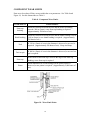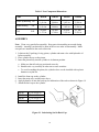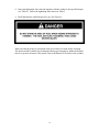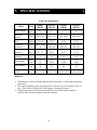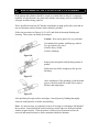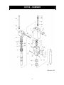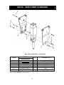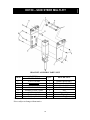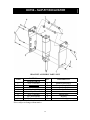
1
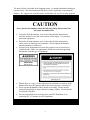
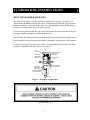
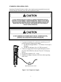
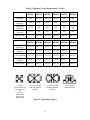
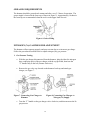
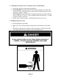
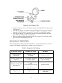
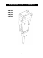
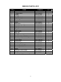
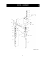
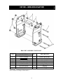
HYDRAULIC
HAMMERS
SERVICE
MANUAL
HH100
HH150
HH300
HH500
HYDRAULIC
HAMMERS
®
1
CONTENTS
1.
Safety Information
Page 2
Safety Decals
Safety Symbols
2.
Operating Instructions
Page 5
How the Hammer Operates
Mounting the Hammer to Carrier
Connecting Hoses
Daily Inspection before Operation
Initial Startup, Hammer Break-in
General Operation Instructions
Cold Weather Startup and Operation
Underwater Operation
Storage
Tool Replacement
3.
Maintenance
Page 12
Hydraulic Oil
Checking Condition of Hydraulic Oil
Fasteners
Greasing Requirements
Nitrogen (N2) Gas Pressure Adjustment
Oil Leakage Inspection
Gas Leakage Inspection
4.
Disassembly and Assembly
Page 19
Disassembly
Inspection of Parts
Component Wear Limits
Assembly
5.
Specifications
Page 27
6.
Refinishing of Pistons and Cylinders
Page 28
7.
Troubleshooting Diagnosis
Page 29
8.
Parts List and Illustrations
Page 31
2
1. SAFETY INFORMATION
•
•
•
•
•
•
•
•
•
•
•
•
•
•
•
•
•
•
•
•
•
Always read the information in this manual before operating the hammer. Failure to
do so can result in personal injury or damage to the equipment.
Check that all safety decals attached to the hammer and carrier are legible. Replace
worn or illegible decals.
Do not use drugs or alcoholic beverages that impair alertness or coordination while
operating the carrier or hammer. An operator taking prescription drugs must obtain
professional medical advice to determine if he/she can safely operate the carrier and
hammer.
Work at a slow pace when learning to operate the hammer.
Operator training must consist of a demonstration and verbal instruction.
New operators must start in an area free of bystanders. He/she must become familiar
with all carrier controls before operating the hammer.
Be aware of any prohibited uses in work areas. (Excessive slopes, poor or dangerous
terrain conditions and utility hazards.)
Operate the carrier or hammer from the operator’s seat ONLY. Make sure the seat
is fastened securely before activating controls.
Keep hands and feet on the controls at all times while the hammer is operating.
Always operate the carrier with the outriggers firmly positioned on the surface.
Make sure all controls (levers and pedals) are in NEUTRAL before starting the
carrier.
NEVER leave the carrier with the engine running. ALWAYS ENGAGE THE
PARKING BRAKE.
Make certain there are no persons within the arc determined by the movement of
stabilizers, front bucket or backhoe boom with the hammer at full extension.
Never operate with any person near the hammer or between the hammer and the
operator.
Replace all faulty or leaking hydraulic hoses or fittings before operation.
Travel with the hammer in the full tuck (transport) position only.
Never operate the hammer with the tool retaining pin removed.
Wear safety goggles, hearing protection and hard hat while operating the hammer.
Before leaving the operator’s seat, always lower the carrier boom or bucket arms.
Stop the engine before attempting to make any repairs or adjustments to either the
carrier or the hammer.
ALWAYS OBSERVE ALL SAFETY INSTRUCTIONS APPLICABLE TO
YOUR CARRIER.
3
SAFETY DECALS
The decals shown below are attached to the hammer when shipped from the factory.
Read and understand them before operating the hammer. Replace any decal that has
become worn, damaged or illegible. Decals can be ordered through Repair Parts
Department.
CAUTION
DANGER
This symbol may appear on
the hammer or in the text of
this manual. It is used to alert
the operator of an action that
can place him/her or others in
a life threatening situation.
This symbol appears in the
text of this manual to identify
an action or condition that
can result in damage to the
hammer or other equipment.
4
The notice below is included in the shipping carton. It contains information relating to
operator safety. Read and understand this notice before unpacking or operating the
hammer. We suggest you retain this notice and include it in your local safety program.
CAUTION
Never operate the hammer unless the following Safety Instructions have
been read and understood.
•
•
•
•
•
•
Projectiles from the hammer, tool, rock or other broken material may
enter the operator’s area and cause serious or fatal injury. Use personal
protection equipment.
Projectiles from the hammer, tool, rock or other broken material may
cause serious or fatal injury to bystanders. Do not operate the hammer
when bystanders are in the area.
In some cases, the hammer may enter the operator’s area if a bracket or
cylinder breaks. Make sure appropriate shields are used when operating
the hammer with this type of equipment.
Shown above is a copy of a decal that must be installed on a surface of the
hammer that faces the operator and on the carrier operator’s control area.
Never operate the hammer if these decals are missing. Decals must be
inspected periodically to ensure that all wording is legible. Decals should
be replaced if illegible.
Decals can be obtained at no charge from your IPC Distributor or by
contacting IPC’s Customer Service Department.
5
2. OPERATING INSTRUCTIONS
HOW THE HAMMER OPERATES
The main valve (Figure 1) for the hammer is built into the cylinder. Hydraulic oil is
supplied into the hammer through this valve. During the upward stroke, the pressure in
the upper chamber is released via the main valve and through the outlet. High pressure
in the lower chamber then forces the piston upward.
As soon as the piston reaches the upper end of the stroke, the main valve directs flow to
the upper chamber causing it to become high pressure.
Since surface A is greater than surface B, the piston is driven downward with the help of
the accumulated energy from the gas chamber, creating the impact stroke of the hammer.
At the point of impact, the main valve shifts, releasing the high pressure from the upper
chamber, enabling the upward stroke to occur again.
GAS
CHAMBER
UPPER CHAMBER
(VARIABLE
PRESSURE)
PRESSURE
RECIEVING
SURFACE A
BUILT-IN MAIN
VALVE
MIDDLE CHAMBER
(LOW PRESSURE)
PRESSURE
RECIEVING
SURFACE B
LOWER CHAMBER
(HIGH PRESSURE)
TOOL
Figure 1. Principles of Operation.
(Refer to Table 10.)
6
MOUNTING THE HAMMER TO THE CARRIER
1. Skid Steer Loader
All hammers are mounted to hammer brackets, which are then mounted to an adapter
plate using two pins. The adapter plate is mounted to the quick mount of the carrier. To
remove the hammer, first disconnect the hydraulic couplers from the inlet and outlet
ports and detach the quick mount. Seal off all plugs and hoses to prevent dust, dirt and
foreign particles from entering the system.
2. Rubber-Tired Backhoes and Excavators
All hammers are mounted to hammer brackets. The hammer brackets are mounted to
the stick of the carrier using two pins. To remove the hammer, first disconnect the
hydraulic couplers from the inlet and outlet ports. Seal the couplers and hoses to prevent
dust, dirt, and foreign particles from entering the system. Remove the “mounting pins”
to detach hammer and bracket from the carrier stick.
CONNECTING HOSES
Connect the two hydraulic hoses to the inlet and outlet ports of the carrier using hose
couplers. When connecting, make sure that the couplers are clean and engaged securely.
DAILY INSPECTION BEFORE OPERATION
1. Check the carrier hydraulic oil level before operation. The hydraulic oil level must
be correct for proper operation.
2. Check the hydraulic oil for any signs of contamination or discoloration. If any signs
of contamination appear, change the oil. (Refer to Table 2.)
NOTE: Do not mix different types of hydraulic oil.
3. Inspect all hoses and fittings for leaks or damage. Check all fasteners and tighten as
required. Replace any broken fasteners.
4. The hammer must be greased daily before use. Ten shots of grease with a grease
gun is adequate. The hammer should be greased every 2-3 hours during operation.
(See Figure 2)
5. Check the temperature of the hydraulic oil. Optimum operating temperature is 100°/
180° F (40°/80°C). The unit may not function properly and seal damage may result if
the hydraulic oil temperature goes beyond the recommended range.
Figure 2. Hammer Lubrication Point
7
INITIAL STARTUP, HAMMER BREAK-IN
New or rebuilt hammers require 20-40 minutes of operation at half the rated speed as a
break-in period. This allows for proper lubrication of all moving parts and for all sliding
surfaces to mate properly.
GENERAL OPERATING INSTRUCTIONS
1. Never apply the tool with a side load. The tool must always be pressed firmly
against, and be perpendicular to the material to be broken. Failure to do so can cause
tool or seal failure.
2. Impact action must be stopped immediately when the object has been broken.
3. Do not pry with the tool. This may cause the tool to break or cause abnormal wear to
the tool bushings.
4. Avoid continuous impact on the same area for more than one minute. Continuous
impact may cause a rapid increase in oil temperature and improper hammer
operation.
5. Break large objects from the outside edges and work inward.
6. Do not submerge the hammer in water. The hammer is not watertight, and damage
can occur if used in this manner. Consult your dealer for underwater applications
(Ref. Figure 3.)
7. Do not use the hammer to move very large or heavy broken objects. This can cause
damage to the hammer and carrier.
8. Do not use the hammer as a lifting device.
9. Do not operate the hammer when boom cylinders are at their extreme ends. This
may cause damage to the cylinders.
10. Stop operation immediately if hoses vibrate abnormally or impact energy is
dramatically reduced. Consult Section 7. “Troubleshooting Diagnosis” for
additional information.
COLD WEATHER STARTUP AND OPERATION
Note: Internal parts of the hammer will be damaged if proper warm-up procedures are
not applied in cold weather.
1. Warm the hydraulic system of the carrier before starting the hammer. Circulate the
oil in carrier system until it is warm to the touch or approximately 60°F (15°C)
2. With engine at half throttle, activate the hammer for 5 seconds and stop for 15
seconds. Repeat cycle for 2 to 3 minutes.
8
UNDERWATER OPERATION
Operation of hydraulic hammers under water requires proper preparation to prevent
internal damage to hammer parts and carrier hydraulic system.
1. To prepare the hammer for underwater operation you will
need an external compressed air supply.
a. For HH100 through HH500, 5 –10 CFM at 50 to 90 psi is
adequate.
b. For HH750 and larger, 20 to 50 CFM is required.
2. Connect air supply line to front cap threaded port (remove
plug P/N 3Z01-FP0038 as shown.) Thread is 3/8 inch pipe
tapered.
3. Set pressure regulator to 50 – 90 psi.
4. Maintain air supply to hammer at all times when operating
under water
PRESSURE REGULATOR
Figure 3. Air Compressor Supply
9
STORAGE
1. Short Term
If the hammer will not be used for periods of one week or more, the tool should be
removed from the hammer and hydraulic oil must be applied to the piston bottom. The
hammer should be stored indoors standing vertically in the working position.
2. Long Term
For storage of more than 2 - 3 weeks or where condensation or corrosion is prevalent
(salt-water areas) note the following instructions. Remove and clean the tool. Flush the
front cap with clean solvent or hydraulic oil. Coat the exposed portion of the piston with
grease, apply grease to the tool and re-install. Store the hammer vertically and away
from standing moisture. To start the hammer after long term storage, remove the tool
and inspect the exposed portion of the piston for corrosion. If corrosion is found do not
use the hammer until the defective piston has been repaired or replaced.
TOOL REPLACEMENT
10
Carefully drive out the tool spring pin.
Push the tool set pin up and out of the front cap
using a screwdriver or round bar.
Note: Check Table 1, Page 11, before handling
tools.
For models HH100 through HH750, manual
removal is possible.
For hammer models HH1000 and larger use
hoist and sling as shown. Check for sling load
rating and compare to
Table 1, Page 11.
When installing the tool in the hammer,
reverse steps 1 through 4 above. Note that tool
spring pin must be inserted with the slot or
open side away from the tool set pin.
4
SLING ANGLES
NOT SMALLER THAN:
o
60
1/3
11
1/3
1/3
Figure 4. Tool Replacement
Table 1. Standard Tool Weights
HAMMER MODEL
HH100
HH150
HH300
HH500
HH750
HH1000
HH1500
HH2000
HH3600
HH4500
HH5800
HH8000
WEIGHTS
kg
lbs.
3.6
7.
14.
15.
23.
37.
45.
74.
118.
152.
174.
214.
8.
15.
30.
32.
51.
82.
99.
162.
260.
334.
381.
470.
12
3. MAINTENANCE
HYDRAULIC OIL
Note: It is not recommended to mix types of hydraulic oils. Check carriers hydraulic oil
recommendations before adding hydraulic oil.
1. Check the oil level, oil filter condition and oil cooler in the carrier periodically.
2. Replace the hydraulic oil every 600 hours and the filter every 100 hours, or
according to carrier recommendations.
3. Always be aware of any abnormalities in the operation of the hammer such as
changes to hammer blow speed, impact force or oil temperature. The oil
temperature should not exceed 180°F (80°C).
4. Check the condition of the hydraulic oil as specified in Table 2.
CHECKING CONDITION OF HYDRAULIC OIL
Note: Refer to carrier service manual for proper class and type of hydraulic oil.
Hydraulic oil must be changed more frequently than the carrier instruction manual
recommends. This is because hammer operation requires more oil circulation than
normal operation. Oil condition can be visually checked as specified in Table 2.
Table 2. Hydraulic Oil Conditions
COLOR
CONDITION
Transparent and no color change
Good
Transparent but too bright
Oil Mixed
Milky white
Air and / or water mixed
Dark and dirty with odor
Deteriorated
Transparent but with black spots
Foreign particles mixed
Bubbly
Grease mixed
13
FASTENERS
Inspect all bolts and nuts for tightness. Tighten as required. (Refer to Table 4.) Replace
all missing or damaged fasteners before operating the hammer.
Fastener bolt and nut sizes are listed in Table 3. These are wrench sizes (distance across
flats.)
Table 3. Bolt Sizes
VALVE BOX
GAS VALVE
HAMMER
NIPPLES
(mm.)
BRACKET
BOLTS
(mm.)
SIDE
RODS
(mm.)
LIFTING
EYES
(inches)
*CAP
BOLTS
SET
BOLTS
(mm.)
100
19
*28
14
½”-13pt
NA
NA
150
30
36
32
½”-13pt
NA
NA
300
30
36
41
½”-13pt
NA
NA
500
30
36
41
¾”-10pt
NA
NA
750
30
36
46
¾”-10pt
NA
NA
1000
36
50
46
¾”-10pt
NA
NA
1500
36
50
54
¾”-10pt
*14
30
2000
36
50
54
*17
30
3600
46
60
63
*17
32
4500
46
75
71
*17
32
5800
46
75
85
*19
41
1” Crow
Foot
1” Crow
Foot
1” Crow
Foot
8000
50
75
90
*19
41
1” Crow
Foot
7/8”9unc
7/8”9unc
1”-8unc
1 ¼”8unc
1 ½”6unc
* Allen Wrench Sizes
14
CAP
(inches)
1” Crow
Foot
1” Crow
Foot
1” Crow
Foot
1” Crow
Foot
1” Crow
Foot
1” Crow
Foot
1” Crow
Foot
1” Crow
Foot
BODY
(mm.)
36
36
36
36
36
36
36
36
36
36
36
36
Table 4. Tightening Torque Requirements (Ft. lbs.)
Side Rod
HH100
HH150
HH300
HH500
HH750
HH1000
NA
400 ±35
550 ±35
550 ±35
NA
NA
Side Rod
Back Nut
Front Cap
Set Bolt
Back Cap
Set Bolt
NA
NA
NA
NA
730 ±35
770 ±35
175 ±35
NA
NA
NA
NA
NA
175 ±35
NA
NA
NA
NA
NA
Bracket Bolt
175 ±35
260 ±35
260 ±35
260 ±35
260 ±35
400 ±35
HH1500
HH2000
HH3600
HH4500
HH5800
HH8000
880 ±35
880 ±35
1100 ±35
1850 ±75
2560 ±75
3300 ±75
280 ±20
280 ±20
330 ±20
330 ±20
590 ±35
590 ±35
Valve Cap Bolt
175 ±20
280 ±20
330 ±20
330 ±20
480 ±35
480 ±35
Mode Valve
Set Bolt
N/A
70 ±3
70 ±3
70 ±3
Bracket Bolt
400 ±35
840 ±35
Side Rod
Back Nut
Valve Box
Set Bolt
5
1
1
70 ±3
70 ±3
1320 ±35 2600 ±35 2600 ±35
3
7
1
3
5
3
1
4
4
2
Side Rod
Side Rod Back Nut
Mode Valve Set
Bolt
Valve Cap
Bolt(HH100)
Front Cap Set
Bolt(HH100)
2600 ±35
4
2
6
6
Valve Box Set Bolt
(HH1500, HH2000,
HH3600)
4
2
8
Valve Box Set Bolt
(HH4500, HH5800,
HH8000)
Figure 5. Tightening Sequence
15
2
3
5
Valve Cap Bolt
(HH2000 and up)
GREASING REQUIREMENTS
The hammer should be greased each startup and after every 2-3 hours of operation. The
grease nipple is located at the front cap as shown in Figure 6. Approximately 10 shots in
the front cap are recommended when the tool is at the upper limit of travel.
Figure 6. Grease Fitting
NITROGEN (N2) GAS PRESSURE ADJUSTMENT
The hammer will not operate properly and may not start due to an incorrect gas charge.
Follow the procedure described below to adjust nitrogen (N2) gas pressure.
1. Gas Pressure Testing.
a. With the gas charger disconnected from the hammer, plug the inlet (the nitrogen
hose connection port) of the gas charger with the cap provided, then turn the
“T” handle fully to the left (counter clockwise.)
b.
Remove the gas valve cap located on the hammer back cap and attach gas
charger, see Figure 7.
Figure 7. Connecting Gas Charger to
Hammer
Figure 8. Connecting Gas Charger to
Nitrogen (N2) Supply
c. Turn the “T” handle on the gas charger valve clockwise, and then measure the N2
gas pressure.
16
2.
Releasing Gas Pressure (if over charged or prior to disassembly.)
a. Test the gas pressure as described in paragraph 1.
b. For disassembly loosen the bleeder screw on the gas charger very slowly and
release the N2 gas. Watch the pressure gauge until the nitrogen pressure is fully
released; (see Figure 7 and 10.)
c. If overcharged close the Bleeder Screw when the gas pressure reaches 140-160
psi/10-11 bar (160-175 psi/11-12 bar on HH500 model), then turn the “T” handle
to the left (counter clockwise).
d. Finally, remove the gas charger. Install and tighten the gas valve cap.
3. Refilling Nitrogen (N2) Gas
a. Perform paragraph 2 procedure.
b. Remove the cap on the gas charger, nitrogen hose connection port. See Figure
10.
c. Attach the N2 gas pressure regulator to the gas container. Connect the nitrogen
(N2) Supply tank to the gas charger with the charging kit hose.
Figure 9.
17
Figure 10. Gas Charger Valve
d. Open the main gas valve on the N2 gas container and regulate the N2 gas pressure
(see Figure 8.)
e. Turn the gas charger “T” handle clockwise and adjust N2 gas pressure in the gas
chamber to 140-160 psi/10-11 bar (160-175 psi/11-12 bar on HH500 model).
f. Turn the gas charger “T” handle fully counter clockwise and remove the hose.
Attach the cap to the gas inlet of the charger.
g. Remove the gas charger and attach the gas valve cap and “O” ring firmly to the
gas valve nut on the hammer back cap.
OIL LEAKAGE INSPECTION
Check for oil leakage at the points shown in Table 5. It is not unusual to have a small
amount of oil leakage along the tool or cylinder, (refer to Figure 11.)
Table 5. Diagnosis of Oil Leakage
LEAK LOCATION
POSSIBLE CAUSE
REMEDY
Between front cap
and tool (E).
Damaged or worn
U-packing.
Replace seal kit.
Between cylinder and
nipple (F).
Loose nipple or damaged
O-ring or nipple.
Tighten or replace nipple,
and / or O-ring.
Between cylinder and
back cap (G).
Damaged U-packing or
main
Valve outer sleeve O-ring,
or
Back cap O-ring.
Replace seal kit.
Plug ports (H).
Plugs loosen
Remove plugs and reinstall
with sealant
18
F
H
E
G
Figure 11.
GAS LEAKAGE INSPECTION
Gas leakage can be easily detected using soapy water (refer to Table 6 and Figure 12.)
Table 6. Diagnosis of Gas Leakage
LEAK LOCATION
Gas valve assembly (A) or
Between gas valve assembly
and back cap (B).
Between back cap and
cylinder (C).
POSSIBLE CAUSE
Defective O-ring,
damaged
Spring or gas valve.
REMEDY
Replace gas valve
assembly.
Defective back cap O-ring. Replace back cap O-ring.
Figure 12
19
4. DISASSEMBLY AND ASSEMBLY
DISASSEMBLY
1. Tool
Refer to tool replacement procedures on page 10 and Figure 4.
2. Back cap
Support the cylinder (Figure 13). Loosen and remove four side rods and washers,
then remove the back cap.
3. Front cap (See Table 3 for eyebolt sizes)
Install an eyebolt and suspend the front cap as shown in Figure 13. Pull out the front
cap, being careful not to damage the piston.
Figure 13. Connecting Hoist to Front Cap.
20
4. Main valve
Attach an eye bolt to outer sleeve and remove it by pulling the eyebolt. (Figure 14.)
Remove the main valve. The inner sleeve cannot be removed as it is press fitted and
requires a special tool. Contact the factory for further details.
Figure 14. Removing the Main Valve
5. Piston (See Table 7 for Piston weights)
Note: For large hammers, you may wish to stand the hammer upright with proper
support, and pull the piston upward using a lifting device.
a. Attach an eye bolt to the top of the piston and pull out together with cylinder
sleeve toward the top.
b. It may be useful to use a pry bar as a lever as shown in Figure 15. Be careful to
not damage the piston.
Figure 15. Removing the piston.
6. Cylinder sleeve
Note: Support piston on wood blocks.
Remove the cylinder sleeve from the piston. A plastic hammer or nylon bar can be used
for removal as shown in Figure 16. Do not force the cylinder sleeve. Tap uniformly on
all sides of the sleeve.
Figure 16. Removing Cylinder Sleeve
Table. 7. Piston Weights
21
HAMMER MODEL
HH100
HH150
HH300
HH500
HH750
HH1000
HH1500
HH2000
HH3600
HH4500
HH5800
HH8000
WEIGHTS
kg
lbs.
5.8
6.0
9.7
10.0
17.1
25.4
41.0
64.3
101.0
122.6
153.4
198.1
12.7
13.2
21.3
22.0
37.6
55.9
90.1
141.5
222.2
269.7
337.5
435.8
22
INSPECTION OF PARTS
1. Seals
Seals that are deformed, scratched, worn or aged should be replaced (see Figure 17).
It is recommended that all seals be replaced when disassembling the hammer.
Figure 17. Seal Conditions
2. Moving parts
Check for any scratches or damage on the surface of the piston, cylinder sleeves, main
valve and bottom part of the piston where it strikes the tool. Significantly damaged or
scratched parts must be replaced.
3. Front cap
a. Deformed or worn shank bushings or front cap bushings must be replaced, see
Table 8.
b. A severely worn or damaged tool set pin must be replaced.
4. Replacing the front cap bushing
a. Measure shank and front cap bushings and refer to Table 8 and 9.
b. Remove bushing set pin and bushing spring pin using a hammer and drive pin.
c. The front cap bushing must be torch cut at three locations (at three 120°
grooves) if it is the only bushing to be replaced. Press out the front cap bushing
only if both bushings need replacement.
d. Any scratches in the front cap must be smoothed after bushing removal.
e. Install the new front cap bushing in the correct direction with part numbers on
the bushing facing the installer (away from the hammer.) Because the bushings
are a press, or interference fit, heating of the front cap and cooling of the bushing
will help installation.
f. Insert the bushing set pin and the bushing spring pin.
23
5. Replacing the shank bushing
Note: Replacement of the front cap bushing is highly recommended when replacing the
shank bushing, as the front cap bushing must be removed to replace the shank
bushing.
a. Measure the shank and front cap bushing, refer to Table 8 and 9.
b. Remove bushing spring pin and bushing set pin for shank bushing on the front
cap using a punch and hammer.
c. Press out shank bushing from the cylinder side together with front cap bushing
using a round bar. If the shank bushing is too tight, cutting it with a torch may
be required. A worn moil or chisel can be machined to a square end (at the
working end) to serve as a press mandrel to remove the bushing.
d. Any scratches on the front cap during the cutting operation must be smoothed
out using a hand grinder.
e. Install a new shank bushing after greasing. As bushings are a press, or inference
fit, heating of the front cap or cooling of the bushing will ease installation of the
bushing.
f. Install the bushing set pin and the bushing spring pin.
6. Refinishing surface scratches (see Section 6. Page 28)
a. Cylinder and Cylinder Sleeve
Scratches on the inside surface of the cylinder should be smoothed using a flap
wheel with 240 grit and finish with 360 grit.
b. Piston
Grind off any scratches on the outside surface using a flapwheel with 240 grit and
finish with 360 grit. When polishing the piston or the cylinder bore, it is not
necessary to completely remove scratches as this may remove excess material. (See
Figures 20, 21 and 22.)
c. Main Valve and Sleeves
Main valve and sleeves cannot be polished. Replace if these parts do not slide freely
by finger pressure.
24
COMPONENT WEAR LIMITS
Parts are to be replaced if they are not within the wear parameters. See Table 8 and
Figure 18, for new dimensions see Table 9.
Table 8. Component Wear Limits
COMPONENT
Front cap
bushing
WEAR LIMITS
When the clearance between the tool and the front cap bushing
exceeds .200 in. (5mm), a new front cap bushing is required.
(Approximately 500 hours of use).
Shank bushing
When the clearance between the tool and the shank bushing exceeds
.160 in. (4mm), a new shank bushing is required. (Approximately
700 hours of use).
Tool
If .120 in. (3mm) of wear in the diameter is observed, a new tool is
required. (Approximately 500 hours of use). Keep tool sharp.
Tool set pin
If .080 in. (2mm) of wear in the diameter is observed, a new tool set
pin is required.
Front cap
Piston
If the corner of the front cap is worn to the edge of the front cap
bushing, a new front cap is required.
When indentation or serious damage on the piston surface is
observed, a new piston is required. (Approximately 2,000 hours of
use).
Figure 18. Wear Limit Points
25
Table 9. New Component Dimensions
PART
Front Cap Bushing I.D.
Shank Bushing
Tool
I.D.
O.D.
HH100
HH150
HH300
HH500
41. mm.
1.614 in.
41. mm.
1.614 in.
40. mm.
1.575 in.
51. mm.
2.008 in.
51. mm.
2.008 in.
50. mm.
1.768 in.
61. mm.
2.402 in.
61. mm.
2.402 in.
60. mm.
2.362 in.
66. mm
2.598 in.
66. mm.
2.598 in.
65. mm.
2.559 in.
ASSEMBLY
Note: Clean every part before assembly. Keep parts clean and do not scratch during
assembly. Assembly can basically be done in the reverse order of disassembly. Make
sure parts are installed in the correct direction.
1. Lubricate the U-packing, O-ring, piston, cylinder and main valve with hydraulic oil
before assembly.
2. Place cylinder sleeve on the piston.
3. Insert the piston fully into the cylinder to its bottom position.
a. Make sure that all seals are positioned correctly.
b. Handle seals very carefully in order not to cause scratches.
c. To avoid scratching the piston, the cylinder sleeve can be installed with a plastic
hammer or nylon bar.
4.
5.
6.
7.
Install the front cap on the cylinder.
Insert the main valve and the outer sleeve.
Apply hydraulic oil into the back cap for lubrication of the seals as shown in Figure 19.
Attach the back cap to the cylinder.
HH100
HH150
HH300
HH500
1.7 oz. or 50
1.7 oz. or 50
1.7 oz. or 50
1.7 oz. or 50
cc.
cc
cc
cc
Figure 19. Lubricating Seal in Back Cap.
26
8. Insert and tighten the four side rods together with the washer to the specified torque
(see Table 4.) Follow the tightening order shown in Table 5.
9. Refill the hammer with Nitrogen (N2) gas. Ref. Figure 9.
Make sure that the piston is positioned at the lower end of its stroke before charging.
The piston and the cylinder may be damaged during gas charging by sudden movement
(due to a pressure increase) if the piston is not at the bottom of its stroke in the cylinder.
27
5. SPECIFICATIONS
Table 10. Specifications
ft-lbs.
kg-m
MODEL
HH100
100
14
MODEL
HH150
150
21
MODEL
HH300
300
41
MODEL
HH500
500
70
bpm
700-1300
680-1,370
600-1,200
600-1,080
gpm
l/min
psi
bar
psi
bar
lbs.
kg
inch
mm
inch
mm
lbs.
kg
3.9 - 6.7
15 – 26
1000 – 1600
70
140 – 160
10 – 11
165
75
35
89
1.6
40
1500 – 4500
682 – 2050
3.9-8.0
15-30
1,430-1,700
100-120
140-160
10-11
270
124
41
1,030
2.0
50
2,500-6,500
1,130-2,950
5.3-10.7
20-40
1,430-1,700
100-120
140-160
10-11
440
200
46
1,180
2.4
60
5,000-12,000
2,270-5,440
6.7-12.0
25-45
1,430-1,850
100-130
160-175
11-12
440
200
46
1,180
2.6
65
5,500-14,000
2,500-6,400
ITEM
UNIT
Impact energy
Blows per
minute
Required oil
flow
Operating
pressure
Nitrogen gas
pressure
Total weight
with tool
Total length
Tool diameter
Applicable
carrier
Remarks:
•
•
•
The hammer is to be used within the specified oil pressure, oil flow and gas pressure
parameters.
The carrier hydraulic system relief pressure is to be set at 2,300-2,400 psi (160-170
bar). This is 600 to 800 psi above the hammer “Operating Pressure.”
Hydraulic pressure is to be measured at the hose end of the carrier (output or
pressure hose) when disconnected from the hammer.
28
6.
REFINISHING OF PISTONS & CYLINDERS
If the pistons and cylinders should be scored or scratched due to dirty oil, or improper
hydraulic oil specifications, the piston and cylinder can in many cases be polished and
salvaged, instead of being replaced.
This is possible because the IPC Huskie components are high quality alloy steel and do
not use chromium surface finishes which cannot be polished.
Follow the procedures in Figures 20, 21 & 22 and finish by thorough flushing and
cleaning. These parts can usually be salvaged.
Caution: Wear safety glasses for eye protection
Use hand held air grinder with flap type wheels.
Two grit wheels were used:
#240 for Heavy Polish.
#360 for Finishing.
Figure 20.
Rotate piston and polish with brushing motion of
grinder.
Polish total area before changing to fine grit for
finishing.
Figure 21.
After completion of fine polishing, clean labyrinth
grooves carefully with fine needle file to remove
all burrs and rough edges.
Figure 22.
After polishing all rough surfaces and edges, clean all parts by flushing thoroughly.
Lubricate with hydraulic oil before reassembling.
Note: It is not necessary to completely remove all scoring or scratching to full depth of
the scratches. Instead polish the surfaces until any raised edges are flush and smooth
with the original surface. If this procedure is followed excess material will not be
removed and normal tolerances can be maintained inside the hammer.
29
7. TROUBLESHOOTING DIAGNOSIS
Table 11. Troubleshooting
SYMPTOM
POSSIBLE CAUSE
Hammer
Couplers are not engaged
does not run
Relief valve set incorrectly
Hesitation or
erratic
operation
Malfunction of the hydraulic pump
Nitrogen gas pressure is too high
Main valve is damaged
Piston is damaged
Couplers are not fully engaged
Relief valve set incorrectly
Malfunction of the hydraulic pump
Oil temperature is too high
(exceeds 180°F or 80°C)
Main valve is damaged
Slow impact
speed
Low impact
power
Decreased oil flow
Auto shut-off in operation, tool is
suspended
Excessive bushing wear
Piston is damaged
Nitrogen pressure is too high
Hydraulic oil leakage into the gas
chamber
Malfunction of the hydraulic pump
Deteriorated or contaminated oil
Nitrogen gas pressure is low
Relief valve set incorrectly
Malfunction of the hydraulic pump
30
REMEDY
Connect couplers securely
Adjust main and secondary relief
valve
Repair pump
Adjust gas pressure
Repair or replace main valve
Repair or replace piston
Connect couplers securely
Adjust main and secondary relief
valve
Repair pump
Check oil cooler
Repair or replace damaged main
valve
Avoid simultaneous axis movement
Apply proper down force
Replace worn bushings
Repair or replace piston
Adjust gas pressure
Replace seal kit
Repair pump
Change oil
Adjust gas pressure
Adjust main and secondary relief
valve
Repair pump
Notes
31
8. PARTS LIST AND ILLUSTRATIONS
HH100
HH150
HH300
HH500
32
HH100 PARTS LIST
ITEM
NAME
1
Cylinder
2
Cylinder Sleeve
3
O-Ring*
4
O-Ring*
5
Gas U-Packing*
6
U-Packing*
7
Dust Seal*
8
Piston
9
Main Valve
10
Main Valve Inner Sleeve
11
Main Valve Outer Sleeve
12
O-Ring*
13
Plug
14
Plug O-Ring*
15
Back Cap
16
O-Ring*
17
Gas Valve Assembly
18
Gas Valve Cap with O-Ring
19
Front Cap
20
Grease Nipple
21
Tool Set Pin
22
Tool Spring Pin
23
Back Cap Set Bolt (A)
24
Back Cap Set Bolt (B)
25
Front Cap Set Bolt
26
Nipple
27
Tool Moil (Chisel, Blunt)
NI
Seal Kit
NI
Gas Charger
*Included in seal kit.
NI denotes not illustrated.
33
NUMBER
3A01-2010001
3A01-2010002
3A01-07148A
3A01-07148A
3A01-U01000G
3A01-U01000I
3A01-D01000D
3A01-2010011
3A01-2010122
3A01-2010123
3A01-2010124
3A01-09068B
3A01-2010081
3A01-09040W
3A01-2010031
3A01-07148A
3Z01-G00001
3Z01-G00004
3A01-2010041
3A01-AMT6075
3A01-2010061
3A01-S24080
3A01-B40258
3A01-B40148
3A01-B40148
3Z03-N00201
3A01-201P(Fx,E)
3A01-201SK
3Z01-202GC
QTY.
1
1
1
1
1
4
1
1
1
1
1
1
1
1
1
1
1
1
1
1
1
1
2
2
4
2
1
1
1
Effective 9/98
HH100 – HAMMER
Effective 9/98
34
HH100 – MINI-EXCAVATOR
BRACKET ASSEMBLY PARTS LIST
PART NO.
MODEL HH100
1.
3A01-311020ME
2.
----------------3.
3A01-311050ME
4.
3A01-311060ME
5.
Assembly of Item 3 and 4
6.
3A01-311091ME
7.
By Carrier Model
8.
By Carrier Model
*Sold as matched set w/ hardware
Prices subject to change without notice.
ITEM
QTY
1
1
3
1
4
1
4
2
35
DESCRIPTION
Hammer Bracket(R)*
Hammer Bracket(L)*
Bracket Bolt
Bracket Bolt
Nut
Support Pipe
Bushing
Pin
Effective 9/98
H100 – TERRAMITE MINI-EXCAVATOR
BRACKET ASSEMBLY PARTS LIST
PART NO.
MODEL HH100
1.
3A01-311021TE
2.
----------------3.
3A01-311051TE
4.
3A01-311061TE
5.
Assembly of Item 3 and 4
6.
3A01-311091TE
7.
By Carrier Model
8.
By Carrier Model
*Sold as matched set w/ hardware
Prices subject to change without notice.
ITEM
QTY
1
1
3
1
4
1
4
2
36
DESCRIPTION
Hammer Bracket (R)*
Hammer Bracket (L)*
Bracket Bolt
Bracket Bolt
Nut
Support Pipe
Bushing
Pin
Effective 9/98
HH150 PARTS LIST
ITEM
NAME
1
Cylinder
2
Cylinder Sleeve
3
Cylinder Sleeve O-Ring*
4
Gas U-Packing*
5
U-Packing*
6
Dust Seal*
7
Drain Plug
8
Piston
9
Main Valve
10
Main Valve Inner Sleeve
11
Main Valve Outer Sleeve
12
Main Valve O-Ring*
13
Main Valve O-Ring*
14
Back Cap
15
Back Cap O-Ring*
16
Front Cap
17
Front Cap Plug
18
Shank Bushing
19
Front Cap Bushing
20
Bushing Set Pin
21
Bushing Spring Pin
22
Nipple PF—1/2in.—3/4in. UN
23
O-Ring 1BG-30
24
Side Rod Assembly
25
Side Rod Washer
26
Grease Nipple
27
Tool Set Pin
28
Tool Spring Pin
29
Tool Moil (Chisel, Blunt)
NI
Seal Kit
NI
Gas Charger
30
Gas Valve Assembly
31
Gas Valve Cap with O-Ring
*Included in seal kit.
NI denotes not illustrated.
37
NUMBER
3C01-2020001
3C01-2020002
3C01-07148B
3C01-U01000G
3C01-U01000I
3C01-D01000D
3Z01-DP0014
3C01-2020011
3C01-2020122
3C01-2020123
3C01-2020124
3C01-09060B
3C01-09076B
3C01-2020031
3C01-07148
3C01-2020041
3Z01-FP0038
3C01-10042
3C01-010043
3C01-010044
3C01-S34058
3C03-N00001
3C01-07058B
3C01-010051
3C01-010054
3Z01-GN0018
3C01-010061
3C01S34148
3C01-202P (Fx,E)
3C01-202SK
3Z01-202GC
3Z01-G00001
3Z01-G00004
QTY.
1
1
3
1
4
1
1
1
1
1
1
1
1
1
1
1
1
1
1
2
4
2
2
4
4
1
1
1
1
1
1
1
1
Effective 9/98
HH150 – HAMMER
Effective 9/98
38
HH150 – SKID STEER STANDARD
BRACKET ASSEMBLY PARTS LIST
PART NO.
MODEL HH150
1.
3C01-311020SS
2.
----------------3.
3C01-311050SS
4.
3C01-311060SS
5.
Assembly of Item 3-4
6.
Assembly of Item 3-4
7.
3C01-311090SS
*Sold as matched set w/ hardware
Prices subject to change without notice.
ITEM
QTY
1
1
2
1
3
3
2
39
DESCRIPTION
Hammer Bracket(R)*
Hammer Bracket(L)*
Bracket Bolt
Bracket Bolt
Washer
Nut
Support Pipe
Effective 9/98
HH150 – SKID STEER MULTI-FIT
BRACKET ASSEMBLY PARTS LIST
PART NO.
MODEL HH150
1.
3C01-311021MF
2.
----------------3.
3C01-311051MF
4.
3C01-311061MF
5.
Assembly of Item 3 and 4
6.
3C01-311091MF
7.
By Carrier Model
8.
By Carrier Model
*Sold as matched set w/ hardware.
Prices subject to change without notice.
ITEM
QTY
1
1
3
1
4
1
4
2
40
DESCRIPTION
Hammer Bracket(R)*
Hammer Bracket(L)*
Bracket Bolt
Bracket Bolt
Nut
Support Pipe
Bushing
Pin
Effective9/98
HH150 – SLIP-FIT EXCAVATOR
BRACKET ASSEMBLY PARTS LIST
PART NO.
MODEL HH150
1.
3C01-311022EX
2.
----------------3.
3C01-311052EX
4.
3C01-311062EX
5.
Assembly of Item 3-4
6.
3C01-311092EX
7.
By Carrier Model
8.
By Carrier Model
*Sold as matched set w/ hardware
Prices subject to change without notice.
ITEM
QTY
1
1
3
1
4
1
4
2
41
DESCRIPTION
Hammer Bracket(R)*
Hammer Bracket(L)*
Bracket Bolt
Bracket Bolt
Nut
Support Pipe
Bushing
Pin
Effective 9/98
42
HH300 PARTS LIST
ITEM
NAME
1
Cylinder
2
Cylinder Sleeve
3
Cylinder Sleeve O-Ring*
4
Gas U-Packing*
5
U-Packing*
6
Dust Seal*
7
Drain Plug
8
Piston
9
Main Valve
10
Main Valve Inner Sleeve
11
Main Valve Outer Sleeve
12
Main Valve O-Ring*
13
Main Valve O-Ring*
14
Back Cap
15
Back Cap O-Ring*
16
Front Cap
17
Front Cap Plug
18
Shank Bushing
19
Front Cap Bushing
20
Bushing Set Pin
21
Bushing Spring Pin
22
Nipple PF—1/2in.—3/4in. UN
23
O-Ring
24
Side Rod Assembly
25
Side Rod Washer
26
Grease Nipple
27
Tool Set Pin
28
Tool Spring Pin
29
Tool Moil (Chisel, Blunt)
NI
Seal Kit
NI
Gas Charger
30
Gas Valve Assembly
31
Gas Valve Cap with O-Ring
*Included in seal kit. NI denotes not illustrated.
43
NUMBER
3D01-2030001
3D01-2030002
3D01-07178B
3D01-U03000G1
3D01-U03001X
3D01-D03000D
3Z01-DP0014
3D01-2030011
3C01-2020122
3C01-2020123
3C01-2020124
3C01-09060B
3C01-09076B
3D01-2030013
3D01-07178
3D01-2030041
3Z01-FP0038
3D01-030042
3D01-030043
3D01-060344
3C01-S34058
3C03-N00001
3C03-07058B
3D01-030051
3D01-030054
3Z01-GN0018
3D01-030061
3C01-S34148
3D01-203P(Fx,E)
3D01-203SK
3Z01-202GC
3Z01-G00001
3Z01-G00004
QTY.
1
1
3
1
4
1
1
1
1
1
1
1
1
1
1
1
1
1
1
2
4
2
2
4
4
1
1
1
1
1
1
1
1
Effective 9/98
HH300 – HAMMER
Effective 9/98
44
HH300 – SKID STEER STANDARD
BRACKET ASSEMBLY PARTS LIST
PART NO.
MODEL HH300
1.
3D01-312020
2.
----------------3.
3D01-312050
4.
Assembly of Item 3
5.
Assembly of Item 3
6.
3D01-312090
*Sold as matched set w/ hardware
Prices subject to change without notice.
ITEM
QTY
1
1
4
4
4
2
45
DESCRIPTION
Hammer Bracket(R)*
Hammer Bracket(L)*
Bracket Bolt
Washer
Nut
Support Pipe
Effective 9/98
HH300 – SKID STEER MULTI-FIT
BRACKET ASSEMBLY PARTS LIST
PART NO.
MODEL HH300
1.
3D01-312021MF
2.
----------------3.
3D01-312051MF
4.
Assembly of Item 3
5.
By Carrier Model
6.
By Carrier Model
*Sold as matched set w/ hardware
Prices subject to change without notice.
ITEM
QTY
1
1
4
4
4
2
46
DESCRIPTION
Hammer Bracket(R)*
Hammer Bracket(L)*
Bracket Bolt
Nut
Bushing
Pin
Effective 9/98
HH300 – SLIP-FIT EXCAVATOR
BRACKET ASSEMBLY PARTS LIST
PART NO.
MODEL HH300
1.
3D01-2052EX
2.
----------------3.
3D01-2053EX
4.
Assembly of Item 3
5.
3D01-2054EX
6.
By Carrier Model
7.
By Carrier Model
*Sold as matched set w/ hardware
Prices subject to change without notice.
ITEM
QTY
1
1
5
5
1
4
2
47
DESCRIPTION
Hammer Bracket(R)*
Hammer Bracket(L)*
Bracket Bolt
Nut
Support Pipe
Bushing
Pin
Effective 9/98
HH300 – SIDE MOUNT SKID STEER STANDARD
BRACKET ASSEMBLY PARTS LIST
PART NO.
MODEL HH300
1.
3D01-312023SM
2.
----------------3.
3D01-312053SM
4.
Assembly of Item 3
5.
3D01-312091SM
*Sold as matched set w/ hardware
Prices subject to change without notice.
ITEM
QTY
1
1
6
6
2
48
DESCRIPTION
Hammer Bracket(R)*
Hammer Bracket(L)*
Bracket Bolt
Nut
Support Pipe
Effective 9/98
HH500 PARTS LIST
ITEM
NAME
1
Cylinder
2
Cylinder Sleeve
3
Cylinder Sleeve O-Ring*
4
Quad Ring*
5
Back Up Ring*
6
U-Packing*
7
Dust Seal*
8
Drain Plug
9
Step Seal W/ O-Ring*
10
Piston
11
Main Valve
12
Main Valve Inner Sleeve
13
Main Valve Outer Sleeve
14
Main Valve O-Ring*
15
Main Valve O-Ring*
16
Back Cap
17
Back Cap O-Ring*
18
Front Cap
19
Front Cap Plug
20
Shank Bushing
21
Front Cap Bushing
22
Bushing Set Pin
23
Bushing Spring Pin
24
Nipple PF—1/2in.—3/4in. UN
25
O-Ring
26
Side Rod Assembly
27
Side Rod Washer
28
Grease Nipple
29
Tool Set Pin
30
Tool Spring Pin
31
Tool Moil (Chisel, Blunt)
NI
Seal Kit
NI
Gas Charger
32
Gas Valve Assembly
33
Gas Valve Cap with O-Ring
*Included in seal kit.
NI denotes not illustrated
49
NUMBER
3G01-2050001
3G01-2050002
3D01-07178B
3G01-170520
3G01-170523
3D01-U03000I
3D01-D03000D
3Z01-DP0014
3G01-170521
3G01-2050011
3C01-2020122
3C01-2020123
3C01-2020124
3C01-09060B
3C01-09076B
3D01-2030031
3D01-07178A
3G01-2050041
3Z01-FP0038
3D01-030042
3G01-050043
3D01-060344
3C01-S34058
3C03-N00001
3C03-07058B
3D01-030051
3D01-030054
3Z01-GN0018
3D01-030061
3C01-S34148
3G05-205P(Fx,E)
3G01-205SK
3Z01-202GC
3Z01-G00001
3Z01-G00004
QTY.
1
1
3
1
1
2
1
1
2
1
1
1
1
1
1
1
1
1
1
1
1
2
4
2
2
4
4
1
1
1
1
1
1
1
1
Effective 9/98
HH500 – HAMMER
Effective 9/98
50
HH500 – SKID STEER STANDARD
BRACKET ASSEMBLY PARTS LIST
PART NO.
MODEL HH500
1.
3D01-312020
2.
----------------3.
3D01-312050
4.
Assembly of Item 3
5.
Assembly of Item 3
6.
3D01-312090
*Sold as matched set w/ hardware
Prices subject to change without notice.
ITEM
QTY
1
1
4
4
4
2
51
DESCRIPTION
Hammer Bracket(R)*
Hammer Bracket(L)*
Bracket Bolt
Washer
Nut
Support Pipe
Effective 9/98
HH500 – SKID STEER MULTI-FIT
BRACKET ASSEMBLY PARTS LIST
PART NO.
MODEL HH500
1.
3D01-312021MF
2.
----------------3.
3D01-312051MF
4.
Assembly of Item 3
5.
By Carrier Model
6.
By Carrier Model
*Sold as matched set w/ hardware
Prices subject to change without notice.
ITEM
QTY
1
1
4
4
4
2
52
DESCRIPTION
Hammer Bracket(R)*
Hammer Bracket(L)*
Bracket Bolt
Nut
Bushing
Pin
Effective 9/98
HH500 – SLIP-FIT TLB / WLB
BRACKET ASSEMBLY PARTS LIST
PART NO.
MODEL HH500
1.
3D01-31203TLB
2.
----------------3.
3D01-31204TLB
4.
3D01-31205TLB
5.
Assembly of Item 3 and 4
6.
3D01-31209TLB
7.
By Carrier Model
8.
By Carrier Model
*Sold as matched set w/ hardware.
Prices subject to change without notice.
ITEM
QTY
1
1
4
1
5
1
4
2
53
DESCRIPTION
Hammer Bracket (R)*
Hammer Bracket (L)*
Bracket Bolt
Bracket Bolt
Nut
Support Pipe
Bushing
Pin
Effective 9/98
HH500 – SLIP-FIT EXCAVATOR
BRACKET ASSEMBLY PARTS LIST
PART NO.
MODEL HH500
1.
3D01-2052EX
2.
----------------3.
3D01-2053EX
4.
Assembly of Item 3
5.
3D01-2054EX
6.
By Carrier Model
7.
By Carrier Model
*Sold as matched set w/ hardware
Prices subject to change without notice.
ITEM
QTY
1
1
5
5
1
4
2
54
DESCRIPTION
Hammer Bracket(R)*
Hammer Bracket(L)*
Bracket Bolt
Nut
Support Pipe
Bushing
Pin
Effective 9/98
HH500 – SIDE MOUNT SKID STEER STANDARD
BRACKET ASSEMBLY PARTS LIST
PART NO.
MODEL HH500
1.
3D01-312023SM
2.
----------------3.
3D01-312053SM
4.
Assembly of Item 3
5.
3D01-312091SM
*Sold as matched set w/ hardware
Prices subject to change without notice.
ITEM
QTY
1
1
6
6
2
55
DESCRIPTION
Hammer Bracket(R)*
Hammer Bracket(L)*
Bracket Bolt
Nut
Support Pipe
Effective 9/98
HYDRAULIC HAMMERS
IPC INDUSTRIES, INC.
194 N. BRANDON DRIVE
GLENDALE HEIGHTS, IL 60139
TOLL FREE 1-800-487-5431
PHONE 630-893-5558 FAX 630-790-3751
®
56