1
♦ PRECISION INSTRUMENTS FOR TEST AND MEASUREMENT ♦
1689/1689M SERIES
Precision
RLC Digibridge
User and Service Manual
WARNING
OBSERVE ALL SAFETY RULES
WHEN WORKING WITH HIGH VOLTAGES OR LINE VOLTAGES.
Dangerous voltages may be present inside this instrument. Do not open the case
Refer servicing to qulified personnel
HIGH VOLTAGES MAY BE PRESENT AT THE TERMINALS OF THIS INSTRUMENT
WHENEVER HAZARDOUS VOLTAGES (> 45 V) ARE USED, TAKE ALL MEASURES TO
AVOID ACCIDENTAL CONTACT WITH ANY LIVE COMPONENTS.
USE MAXIMUM INSULATION AND MINIMIZE THE USE OF BARE
CONDUCTORS WHEN USING THIS INSTRUMENT.
Use extreme caution when working with bare conductors or bus bars.
WHEN WORKING WITH HIGH VOLTAGES, POST WARNING SIGNS AND
KEEP UNREQUIRED PERSONNEL SAFELY AWAY.
CAUTION
DO NOT APPLY ANY VOLTAGES OR CURRENTS TO THE TERMINALS OF THIS
INSTRUMENT IN EXCESS OF THE MAXIMUM LIMITS INDICATED ON
THE FRONT PANEL OR THE OPERATING GUIDE LABEL.
vii
Instruction Manual Changes
These supplementary pages contain information of improvements or modifications not
documented in the current manual. All references to GenRad in the manual now apply
to QuadTech, Inc.
Page v - Table of Contents (Parts Lists and Diagrams - Section 6)
• Power supply assembly, board layout and schematic (pages 6-15 & 6-16) replaced
by Power supply assembly part number 700011.
Page xii - Specifications (High-Speed Measurement/In terface Option, Environment
Power & Mechanical)
• Part Number for High-Speed Measurement /Interface Option should be 1689-9630.
• Power should be 90 - 250Vac, 50 - 60 Hz. Voltage switching is automatic and no
longer selected by rear panel switch. 60 watts maximum.
• Weight: 1689 should be 10 lbs. (4.5 kg)
1689M should be 14 lbs. (6.4 kg)
• Environment reads, Altitude < 2000m, Installation Category 1, Pollution Degree 1
Page 1-8 - Figure 1-3 & Figure 1-4, 1689 and 1689M Rear View
• Rear view should show new power supply assembly (PN 700011) without linevoltage switch.
Page 1-9 - Table 1-2, Rear Connectors and Controls
External bias connector receives cable 1658-2450 (not sum>lied
• RefNo. 1 with instruments ship_ped after July 97. available on request). Fuse is 2/lOA, 250V,
3AG Type, Fast Blow. Replace only with the same type and rating.
• Ref No. 3 - Air filter has been deleted.
===
&
Fuse is 6/IOA, 250V, 3AG Type, Slow Blow. Replace only with
Ref No. 5 the same type and rating. To replace, remove fuse drawer by pressing up on release
tab.
• Ref No. 6 - Line-voltage switch has been deleted, power input is from 90 - 250V
AC.
Page 1-11, 1-12 - Table 1-3, 1-4 Accessories and Options for the 1689/1689M
• A quantity of two spare fuses are supplied, 6/lOA, 250V, 3AG Type, Slow Blow
(QuadTech part number 5330-1100)
• Bias cable 1658-2450 with built-in fuse (not supplied with instruments shipped after
July 97. available on request). A quantity of one spare fuse is supplied, 2/lOA, 250V,
3AG Type, Fast Blow (QuadTech part number 5330-3200)
• Part number for the recommended High-Speed Measurement/Interface Option has
changed from 1689-9620 to 1689-9630.
Page 2-1 - Safety Inspection
•
&
Before operating the instrument inspect the power inlet module on the rear of the
unit to ensure that the properly rated fuse is in place, otherwise damage to unit is
possible. Fuse is 6/1OA, 250V, 3AG Type, Slow Blow.
Instruction Manual Changes (continued)
The 1689 is shipped with a standard U.S. power cord, QuadTech PN 4200-0300 (with
Belden SPH-386 socket or equivalent, and 3 wire plug conforming to IEC 320) or an
approved international cord set. Make sure the instrument is only used with these or
other approved international cord sets, which ensures the instrument is provided with
connection to protective earth ground.
In all installations the instrument should be positioned with consideration for ample air
flow to the side and rear panel ventilation holes. An open space around the instrument of
at least 3 inches (75mm) is recommend. The surrounding environment should be free
from excessive dust to prevent contamination of electronic circuits.
WARNING
If this instrument is used in a manner not specified in this manual
protection to the operator and equipment may be impaired.
Page 2-2 - Power-Line Connection
• Power line switch for 115V or 230V operation has been removed, switching is
automatic for voltages between 90 - 250V AC.
• Figure 2-2 does not apply. Only certified line cords which comply with IEC 227 or
IEC 245 should be used.
Page 2-4 - Paragraph 2.6.2, External Bias
• Bias cable 1658-2450, (not supplied with instruments shipped after July 97, available
on request).
Page 2-5 - Paragraph 2.7.1, High-Speed Measurement/Interface Option
• Part number for the High-Speed Measurement/Interface Option has changed from
1689-9620 to 1689-9630.
Page 3-1 - Paragraph 3.J.2 Startup, step a
• Power line switch for 115V or 230V operation has been removed, switching is
automatic.
Page 3-64 - Paragraph 3.12 Data Output and/or Programming via IEEE-488 Bus
• Part number for the High-Speed Measurement/Interface Option has changed from
1689-9620 to 1689-9630.
Page 5-3 - Paragraph 5.3, Repair and Replacement of Circuit Boards
• Contacts for QuadTech are:
Sales & Service
800-253-1230
Tecimical Assistance 978-461-2100
Page 5-4 - Table 5-1, Caution Note
• Power line switch for 115V or 230V operation has been removed, switching is
automatic.
Page 5-11 - Figure 5-1, 1689 Rear and Bottom View
• Rear view should show new power supply assembly (PN 700011) without linevoltage switch.
A
Page 5-13 Paragraph 5.5.1, Disassembly of 1689 Digibridge, step e and f
• Delete step e, there is no longer a protective cover. CAUTION note does not apply,
the fan has been removed.
• Step f, the power supply is secured by only 4 screws rather than 5.
700011.
Instruction Manual Changes (continued)
Page 5-41 -Table 5-7, Capacitance Accuracy Checks
.QDR Display Max column corrected as follows:
Nominal
Value
QDR Max
10 pF
100 pF
1500 pF
1500 pF
1500 pF
6400 pF
10 nF
25 nF
25 nF
25 nF
100 nF
200 nF
400 nF
400 nF
400 nF
1000 nF
6100 ppm
2500 ppm
700 ppm
1000 ppm
1700 ppm
500 ppm
500 ppm
500 ppm
800 ppm
1500 ppm
500 ppm
600 ppm
600 ppm
900 ppm
1600 ppm
600 ppm
Page 6-2 -Figure 6-2, 1689 Rear View
Rear view should show new power supply assembly (PN 700011) without line
voltage switch.
Page 6-3 -Mechanical Parts List for 1689, Rear
Items 4 through 7 (power connector, fuse extractor post and line voltage switch and
cover) deleted on new power supply assembly.
Page 6-4 -Figure 6-2(A), 1689M Rear View
Rear view should show new power supply assembly (pN 700011) without line
voltage switch.
Page 6-5 -Mechanical Parts List for 1689M, Rear
Items 3 through 6 (power connector, fuse extractor post, line voltage switch and
cover) deleted on new power supply assembly.
Page 6-15 & Page 6-16 -Parts Lists and Diagrams
Power Supply Assembly shown, PN 1689-2005, has been replaced by Power
Supply Assembly, PN 700011. The 700011 Assembly must be repaired by module
exchange.
Page 6-19, 6-20, 6-21, & 6-22 -Parts Lists and Diagrams
High-speed interface board shown, PN 1689-4720, has been replaced by PN 1689
4620. See instructions supplied with the 1689-9630.
Table of Contents
OPERATION - - SECTl<l'I 3
SPECIFJCATl<Nl
.v
\\lARRANTY . . .
.xvii
INIROOUCTI CN
SECfICN
3.1
l
l .l
PURPOSE . . . . .
I . 2 c:rnrnAL DESCR I PT! <l'l . .
. I Basic Digib r i dge 1689
.2 Basic Di gibr i dge 1689M
.3 Interface Options
. 4 Refere nces
O'.X'llROLS, IN'.>ICA'Il'.RS , etc.
A<XESSOOIES . . . . .
<XJN:>FNSFD CPIBATJNJ INS'IRlCI'ICNS
1.3
1 .4
I· l
1- 2
2
2
3
3
I· 3
1 -1 0
1 . 14
INSTALLATJCN - - SECfION 2
UNPA<KINJ AND INSPWI'ICN
DIM!NSJONS
POAIB-LINE
....
~ICN
LINE-VOLTAGE REQJLATICN
TEST - F lXTURE CXN£CI"IO'lS
.1 For 1689
. 2 For 1689M
2. 6 BIAS VOLTAGE FCR 'lllE otn:
.1 lnHrnal Bias
.2 Externa l Bias
2. 7 HAN:>LER INI'fllFACE (a>TJCN)
. I . . vi a High-Speed Optio n
. 2 .. via Regular - Speed Opt i on
. 3 Ti ming
2 . 8 IEEE-488 IN1'FRF'ACE (OPTI0.'1)
.1
Purpose
. 2 Inte rf ace Functions
. 3 Signal Identificat i on
. 4 Codes and Addre ss es
2. 9 El':V IRCNvEN'.r
2 . l 0 R.\.a< M)1.JNI'INJ . . . •
2-1
2• I
2- 2
2·3
2-3
3
4
2- 4
4
4
2-5
5
6
7
2- 9
9
10
I1
13
2 ·I 5
2. 15
3- !
I
1
2
. 3 Zeroing
3
. 4 Routine Measurement
3- 4
3 . 2 o::N'®::TI NJ 1liE our
4
.1 Gene ral
4
.2 Int egral Test Fixture (Radia l )
. 3 Usi ng Adaptors {Axia l -Lead Out)
5
8
. 4 EN::: Adaptors, Remote Fixture
9
.5 Extender Cab le (Type 874)
10
. 6 Ex tender Cable (Banana P lugs )
11
. 7 Effect s of Cable Capaci tances
.8 Tweez e rs (Special Test Fi xt ur e) 12
13
.9 Kelvin Clips
3. 3
2 .1
2.2
2.3
2.4
2.5
BASIC PRD'.EJURE
.l General
.2 Startup
~EA.SUREMNI'
PARAMm!lIB ,
3 - 13
RESULTS DISPLAYS, OOIPUfS
13
.1 Parameters (R L C Q D)
14
.2 Equiv Curcuits (Se rie s, Para!)
17
.3 Results PRil'(;IPAL ~UREMNI'
18
SEXXNDARY ~EA.SUREM!Nf
00/ tn-OO
19
19
Units, Multipliers, Blank Disp
20
D/Q in PIM
21
Digit Blanking (Special Funct)
21
Ratio Disp lays (Specia l Func t )
3- 23
3 . 4 PRINCIPAL '!EST <XN:>ITIONS
23
.1 Tes t Frequency
24
. 2 Tes t Voltage
25
. 3 Constant-Voltage Sour ce
25
. 4 Constant- Cur rent Sou rce
26
. 5 Other Conditions
3 . 5 NEASUREM!Nf T~E
3-26
AND IVEASUREMENT RAN:lES
26
. !General
. 2 Measure Rate Se l ection (Keyb 1· d) 28
. 3 Se t t I i ng Time , Progranmed Delay 28
.4 Mea sur e /\'bde & Display Effects
29
.4
.5
.6
.7
ii
i
.5 (nt. eg rat.ion · Ti1ne Factor
29
. 6 Ranges (Changing, Holding , Ti me) 30
. i Time : Median Values, Averaging
32
. 8 Time : I EEE-488 Bus OuLpuL
33
. 9 Time : Low Test Frequency
33
. 10 Measurement Time Surnna r y
34
3 . 6 ACCURACY, TI·IE LIMlTS OF ERRffiS 3-36
. I General
36
.2 Accuracy for Typital Conditions 36
.3 Averag i ng to lmp ro l'C Accuracy
38
.4 Median Value , For BeLter Acc'c y 39
.5 Enhancement for Large & Small Z 39
. 6 Enhancement by Shon Ch L
40
. 7 Cable - Related Errors
41
. 8 Signal Reversing for Powe r Freq 44
3 . 7 BIAS F'CR 1HE our
3- 45
. I Internal Bia s
45
. 2 External Bia s
46
. 3 Suppression of Transients
49
3 . 8 BIN SCRTINJ & <Xl/ N'J-00 RESULTS 3-49
.I Introduction to Binning
49
.2 Sorting Methods
50
.3 Lim it Entry Procedure
51
. 4 Verification of Nominal & L imits 52
.5 Examples of Limit Entry
53
.6 Notes on Limit En t r ies , General 54
. 7 Go/ No-Go and Bin Results
55
.8 Bin Sum Information
55
.9 Binning and Ratio Meas Together 56
3 . 9 KEYOOARD L<XK, FlJl'Cf I Cl'<
A1'V
!~!CNS
M~P
. . . . . 3- 58
.1 Keyboard Lock
58
.2 Fun ct ion Map
59
. 3 Sumnary of Interrogations
59
3 . 10 SPECIAL ~!CNS . . . . .
3 - 60
3. 11 OPERATICN WJ1H A &\NDLER
3-63
3 . 12 DATA <:m'PUT Af-0/ (J{ PR((;R.\\.MJNJ
V IA IEEE-488 OOS . . . . . . 3-64
.I IEEE-4 88 Int er fac e Unused
64
.2 Ta l k - Only Use, for Data Output
64
. 3 Talk / Listen Use, Programning e tc 70
. 4 Output in Compact Binary Format 78
3 . 13 SELF CHECKS AND FAILURE DISPLAYS
. . . . . 3-81
( ERROO COOES)
. I Power-Up Self Ch ec ks
81
. 2 Failure due Lo Signal Overload
82
. 3 .. . due to Abnormal Meas Cycle
82
. 4 .. . due to LC Resonance
82
3 .14 SAM' LE IEEE PR!XRA'v!S
3-83
. I Programn ing Hints
83
.2 Hewlett Packard HP85
84
. 3 Capitol Equ i pm'L PC-488 / IBvl-PC
84
. 4 Nat ' I l nstrm' t GPIB- PCI 1/1131'1- PC 85
iv
TI-IEXl?Y - - SECl' l<N 4
4 . I Il\>1ROOUCT I(N . . . . .
. I General
4- I
I
.2 Brief Description of 1689
I
. 3 Block Di ag ram
2
4. 2 PRIJICI PAL F'IJ1'CTIQllS
4- 4
.1 Elementary Measurement Circui~
4
.2 Fr• quency and Time Sou rce
5
. 3 Sine-\\'a,,•e Generation
5
.4 Dual-Slope lnt•grating Detector 6
SERVICE - - SECl'ICN 5
a.JSTQ..ER SERVICE
5-3
INS'IRUvENf REruRN . . . .
5- 3
.1 Return l\iaterial
3
.2 Packaging
3
5. 3 REPAIR & REPLA<EvE'II' OF' OCWIDS 5 - 3
5.4 P~ VERIFIO\TJQ\I
5-3
.I General
3
.2 Performance verification
4
. 3 Measurem•nt-Time Ch e ckout
8
5 . 5 DI SASSEMlLY AJll> Aa::ESS
5-11
. 1 Disassembly 1689
12
.2 Disassembly 168!M
18
.3 Relocation of ~ Conn•ctor Bkt 22
.4 Access to Internal Components
23
.5 I EEE/ Handler Inte rf ace Options
25
.6 Removal of ;\iiltiplc-Pin Packages 26
5.6 PERIOOIC M\I~
. . . . . 5-26
.I Care of Test Fixture
26
28
. 2 Cleaning Air Filter
.3 Care of Display Panel
28
5 . 7 'IllaJBLE ANALYS I S
. . .. . 5-28
. 1 General
28
. 2 Power-Up Self Chec k s
30
. 3 Batt e ry and Fuse Replacement
33
.4 Power Supply
34
. S Sinewave Generator Checks
35
.6 Front End Ampl i fier s, Switches
36
5 . 8 AcaJRACY VERIF ICATICN
5- 38
. 1 G•neral
38
.2 CMeas'mt Acc'cy, Ranges I 2 3
39
. 3 C Meas ' mt Ace ' cy, Rang e 4
42
. 4 Resistance Mcas 1 mt Accuracy
44
. 5 Inductance Meu'mt Accuracy
45
. 6 D Measureme nt Accura cy
41
. 7 Lim i t Comparison Bins
H
5.9 Rro\LIBRATI Qll
. . . . . . . . 5-51
. I Pre parat io n
51
.2 Zeroing and Se l ecting
53
. 3 Re cal i braL ion, Range 4
53
. 4 Recalibration, Range 3
54
5.1
5.2
.5 Recalibration, Range 2
55
.6 Recalibration, Range 1
56
57
.7 Frequency Calibration
.8 Frequency Correction K Factor
58
5.10 INTERNAL SE1TIN3S
5-60
.1 Address for IEEE-488 Interface
60
.2 Making +5 V Available (Handler) 61
PARTS LISTS AND D IAGRAM3 - - SECTI ~ 6
6.1 GENERAL
6 . 2 REFERF.NJE DES I GN.\.TI ~S
6.3 DIAGRAMS
6-1. 1689 Front, showing mech.parts
6-1A.1689:M Front, showing mech.parts
6-2. 1689 Rear, showing mech.parts
6-2A.1689:M Rear, showing mech.parts
Federal Supply Code, Manufacturers
6-3. :Ma.in Board, schematic sheet 1
6-4. :Ma.in Board, layout sheet 1.
6-5. Main Board, layout sheet 2.
6-1
6- 1
6-5
6-2
6-4
6-2
6-4
6-6
6-7
6-8
6-9
6-6. Main Board, schematic sheet 2
6-7. :Main Board, schematic sheet 3
6-8. Main Board, schematic sheet 4
6-9. Main Board, schematic sheet 5
6 - 1 0 .:Ma i n Bo a r d , s ch ema t i c s h e e t 6
6 - 11 .:Ma i n Bo a r d , s ch ema t i c sh e e t 7
6-12.Power Supply, assembly
6-13.Power Supply Board, layout
6-14.Power Supply, schematic
6-15.Display Board, layout
6-16.Display Board, schematic
6-17.H-S Interface Bd., layout, shl
6-18.H-S Interface Bd., layout, sh2
6-19.H-S Interface, schematic 1,
6-20.H-S Interface, schematic 2,
6-21.H-S Interface, schematic 3,
"6-22.lnterface Board, layout,
6-23.lnterface, schematic,
6-24.Keyboard :Module, assembly
6-25.Keyboard Indicators, detail
6-26.Keyboard, schema.tic
6-10
6-11
6-12
6-13
6-14
6-14
6-15
6-16
6-16
6-17
6-18
6-19
6-19
6-20
6-21
6-22
6-23
6-24
6-25
6-25
6-26
Displays
Measurement results may be displayed in four ways as selected by the keyboard: 1) VALUE, 2) % difference, 3)
RLC difference, and 4) BIN NO.
1) The VALUE display can be one of four pairs of measured quantities Land Q, C and D, C and R, or Rand Q. The primary
display (L, C, or R) has five digi~ of resolution and the secondary display D, Q, or R with C) has four digits of resolution.
2) The % difference display indicates the percent deviation of the measured L, C, or R value from a stored NOMINAL
VALUE. The sign of this deviation is indicated.
3) The RLC difference is similar to the % difference except that the deviation is displayed in appropriate units (ohms, henries,
etc.)
4) The BIN NO. display is the number of the bin (0 through 14) into which the component should be sorted. The testing limits
for these bins are set up by the user in the ENTER mode. These test limi~ may be symmetrical or non-symmetrical about the
NOMINAL VALUE. One bin is used for D or Q rejects and one is used for RLC rejects (outside all limits). The sum of the
number of componen~ sorted into each bin may be displayed (99999 max).
Also displayed during entry or upon interrogation are: test frequency, test voltage, number of measurcments
averaged, delay time, nominal value, bin limi~ and bin sum and codes for SPECIAL FUNCTIONS.
GO/NO-GO lights are also provided and these are active with all modes of measurement display as long as test limits have
been set.
Ranges
Primary Disp/ay:*
C:
.00001 pF to 99999 uF
R:
.000010 to 99999 kO
L:
.00001 nH to 99999 H
% difference (C, R, or L): .0001% to 99999%; RLC difference: same as R, L, or C.
If any of these quantities is negative, the NEG RLC indicator light is lit.
vii
*These ranges may be extended by a factor of more than 10,000 larger or smaller by using the special ratio mode.
Se condary Di&play:
D (with C) or Q (with L or R): . 0001 to 9999
D (with C) or Q (with R) in ppm : 1 ppm to 9999 ppm
R (with C) : . 0001 n to 9999 kO
Ir any of these quantities is negative, the NEG QDR indicator is lit.
Equivalen t Circuit
Either the equivalent SERIES or the equivalent PARALLEL circuit representati on of L, R, or C may be selected
by keyboard control.
Test Frequencie s
Over five hundred test frequencies between 12 Hz and 100 kHz may be selected using the keyboard. These are:
200kHz
I
=
I
-= -60kHz
n
I
= -n- where
n
3kHz
where 2 $ n $ 13
where 4
<
n ~ 256
13 $ n $ 250
If the exact frequency entered is not available, the nearest available frequency will be used. Frequency tolerance is
.01%.
Measurem ent Time
Measuremen t rate is selected via the keyboard. The time required for a complete measurement is typically less
than indicated in Tables A and B ..
viii
TABLE A
GR1689 MEASUREMENT RATE
TEST FREQUENCY
MEASUREMENT
RATE
12 Hz
SLOW
MEDIUM
FAST
MAX IMUM
875 ms
670 ms
670 ms
670 ms
100 Hz
120Hz
1 kHz
940 ms
130 ms
125 ms
110 ms*
940 ms
185 ms
110 ms
100 ms*
970 ms
200 ms
80 ms
40 ms
10 kHz
930 ms
190 ms
75 ms
34 ms
100 kHz
930 ms
190 ms
70 ms
33 ms
Notes:1. If the high-speed option is not used, add 19 ms for MAXIMUM, or 38 ms
for SLOW, NEDIUM or FAST measurement.
2. If the display is value, delta%, or deltaRLC, add 6 to 10 ms.
3. If data is output via the IEEE Bus., add 6 to 12 ms.
4. For ACQ, subtract 22 ms for SLOW, MEDIUM or FAST and 12 ms for MAXIMUM.
TABLE B
GR1689M MEASUREMENT RATE
TEST FREQUENCY
MEASUREMENT
RATE
12 Hz
100 Hz
120 Hz
1 kHz
10 kHz
100 kHz
SLOW
MEDIUM
FAST
MAXIMUM
875 ms
670 ms
670 ms
660 ms
920 ms
120 ms
105 ms
101 ms*
920 ms
170 ms
90 ms
86 ms*
950 ms
180 ms
65 ms
32 ms
920 ms
170 ms
55 ms
22 ms
920 ms
170 ms
55 ms
22 ms
Notes: 1. If the high-speed option is not used, add 12 ms for MAXIMUM,
or 24 ms for SLOW, MEDIUM or FAST measurement.
2. If the display is value, delta% or deltaRLC, add 3 to 5 ms.
3. If data is output via the IEEE Bus, add 3 to 6 ms.
4. For ACQ, subtract 11 ms for SLOW, MEDIUM or FAST and 6 ms for MAXIMUM.
* These times can be shortened by 14 ms with reduced accuracy using the quick acquisition routine.
The measurement times are obtained with use of the high-speed measurement option, continuous
measurement mode, bin number display/handler output, and without IEEE-Bus data output. For other
conditions, refer to the table notes.
If the measurement mode is triggered, programmed delay (settling time), if any, should be added.
Normal power up conditions included a programmed delay of 7/f to 12/f ms depending upon
measurement rate. This delay can be programmed to zero or to any value up to 100 sec.
Test connections can be broken (handler indexing can begin) as soon as data acquisition is complete (ACQ
line low on handler interface). See Note 4 in tables.
i
x
Measurement Modes
Two test modes are available: CONTINUOUS and TRIGGERED.
The CONTINUOUS mode makes successive measurements continuously, updating the display after each
measurement.
TRIGGERED measurements are initiated by the START button, or remotely from the IEEE bus or from the
Handler Interface, and the measurement result is displayed until the next measurement is started.
Average
The AVERAGE of any number of measurements from 1 to 255 may be made as desired in either of the two
MEASURE MODES. In the TRIGGERED mode, the running average is displayed and the final value held until the
START button is again depressed. In the CONTINUOUS mode, only the final value is displayed.
Test Voltage
2
The RMS test voltage is selectable from 5 mV to 1.275 V in 5 mV steps. The accuracy is: (5% + 2 mV) (1 + .001 f ) where f
= frequency in kHz.
This voltage may be applied behind a source impedance (which depends on the range) in which case the selected voltage is
the maximum that will be applied and the voltage will be less at the low impedance end of each range. The voltage may be
applied also behind 25 ohms using the CONSTANT VOLTAGE function in which case the applied voltage will be constant
except when low impedances are measured.
Delay
A delay of from 1 to 99999 ms may be added to allow for settling of external switches and to permit a wider selection
of measurement rates.
DC Bias
An internal bias of 2 V may be applied to capacitors under test by means of the INT BIAS key.
An external bias of up to 60 VDC may be applied to capacitors under test using a panel switch. The applied
current should be limited to 200 mA.
The instrument is protected from damage from charged capacitors with a stored energy up to 1 joule at 60 volts or less.
Protection from higher voltages may be provided by external components.
Zeroing
Open: A simple OPEN operation removes the effects of stray capacitance and conductance of the internal test fixture or
any other test fixture or cable.
Short: A similar SHORT zeroing operation removes the effects of series resistance and inductance.
DUT Connections
The 1689 has a built-in test fixture that will accept radial or axial components. The 1689M has BNC
connectors for attachment to a wide variety of measurement accessories. Four terminal (Kelvin) connections are made to
the device under test. The instrument ground is guard for three-terminal measurements.
x
Keyboard Lock
A combination of keyboard entries makes the keyboard inactive.
Special Functions
Several special features may bl;: :selected. These include:
Direct range setting
Range extension
Choice of integration time
Blanking of lesser digits
Signal Reversal to reduce hum pickup effects
Selection of the median value of three measurements
A routine that reduces transient delays when bias is applied
Automatic parameter selection
Quick acquisition routine
IEEE-488 Bus/Handler Interface Card (1658-9620)
IEEE-488 Bus (J2 on rear panel with option)
All front panel functions are programmable from the bus. All RLC, DQ, and bin data are available as output
to the bus. Output data format: ASCII or Binary.
The following functions, per IEEE-488, have been implemented:
AHI
SHI
T5
Acceptor Handshake (Listener)
Source Handshake (Talker).
Talker with normal and talk-only modes (for systems without a controller),
switch selectable on rear panel.
L4
Listener.
SRI
Service Request (to request service when measurement is complete and the
instrument is not addressed to talk).
RL2
Remote/Local (no local lockout, no return-to-local switch).
PPO
No par all e 1 po 11 .
OC1
Device clear.
DT1
Device Trigger (to start measurement).
CO
No controller functions.
Handler Connections (JI rear panel with option)
1. Outputs, Active low: (Open collector drivers rated at 30 V max. Each will sink 16 mA at 0.4 V. External power and pull-up
resistors required).
Bin 0 through bin 9 (10 lines) -Sorting outputs.
ACQ OVER (1 line)-indicates end of data acquisition. Component may be removed (see TEST TIME).
EOT (1 line)-indicates end of test. Bin No. is valid.
2. Input, Active low:
(0 V < VI < 0.4 V, + 2.5 V < Vh < + 5 V)
Start (1 line)-Initiates new measurement.
Xl
High-Speed Measurement/Interface Option 1689-9820)
Same as above option but also with high-speed capability to increase measurement rate and five more sorting bins (15
lines, open collector drives rated at 15 V max. Each will sink 24 mA at 0.5 V). See Measurement Rate specification, above.
Environment
Operating:
O to 50 degrees C, 0 to 85% relative humidity.
Storage:
-40 to 74degrees C.
When the high-speed option is used, the operating temperature range is O to 40 degrees C.
Temperature Effects (typical)
R, L or C: +/- 5 ppm/degree C.
Q or D: +/- [2 ppm/degree C + (3 ppm/degree C) x (frequency in kHz)]
All specifications refer to 23degree C (calibration temperature).
Power
90 to 125 V or 180 to 250 V AC, 50 to 60 Hz.
Voltage selected by rear panel switch; 50 watts maximum, 40 watts typical. When the high-speed option is
used, the maximum power is 60 watts.
Mechanical
DIMENSIONS (W x H x D):
1689 14.781 x 4.40 x 13.50 in. (375.4 x 111.8 x 342.9 mm) WEIGHT: 13 lbs. (5.9 kg.)
1689M 17.25 x 5.625 x 15.160 in. (438.15 x 142.87 x 385.06 mm) WEIGHT: 17 lbs. (7.71 kg.)
Limit or Error (Accuracy)
Primary Readout C, R, or L
.01% [(I + Kcv) or
xi
i
NOTES:
1. The limit of error is a percent of the reading and may be positive or negative.
2. The largest term of the first bracketed factor should be used.
3. CX, RJc, and Lx are the values of the components being tested, and Cmax, Cmin, Rmax, etc., are range constants
given in Table C.
4. The values of Ks, Kfv, and Kcv are all zero for measurements made at 1 kHz, with the SLOW measurement rate and using a
non-CONSTANT 1 V signal. For other test conditions, these constants may be evaluated using Tables D through G.
5. These specifications assume proper OPEN and SHORT zeroing calibrations made at 1 kHz. Much better accuracy is
possible at extreme impedance values if these zeroing calibrations are recent and made at the test frequency to be used. For
example, the SLOW MEASUREMENT rate typically will give 1 % accuracy when measuring 100 Mohm at 30 Hz, 0.lF at 120
Hz, 0.1 pF at 10 kHz, or 0.1 uH at 100 kHz. Even better accuracy is possible if several measurements are averaged.
6. Although L measurements on the 1689 should be capable of the accuracy stated above, calibrations by the National Bureau
of Standards are specified to .02%; this amount should be added to the 1689 specification for inductance measurements if they
are to be used in any manner involving legal certification.
Secondary Readout R with C
xiii
NOTES:
This is not a percent error but rather the amount, posiu've or negative, by which the D or Q reading may be in error.
Otherwise, the notes for the primary readout apply. When using DQ in PPM, the final term of .0001 should be removed.
xiv
Table F
Kfv as a Function of Frequency and RMS Voltage for Range 1
Frequency
Voltage
12to 30to
lOOto 250to
>l to >3to >6to >10to >20to >50to
<30Hz <lOOHz <250Hz <I kHz lkHz 3kHz 6kHz IOkHz 20kHz 50kHz lOOkHz
1 to l.26V
0.25 to <lV
0. I to <. 25V
0.03 to <.IV
0.01 to <.03V
7
*
20
70
3
6
13
50
*
*
10
2
4
9
35
IOO
1
2
6
25
70
0
I
4
15
50
2
3
6
17
50
6
10
I5
25
70
I5
20
30
60
*
50
65
100
*
*
This range
is not used
above 20kHz.
Not specified
Table G
Kfv as a Function of Frequency and RMS Voltage for Range 2, 3, and 4
Frequency
Voltage
I2to 30to
lOOto 250to
>I to >3to >6to >lOto >20to >50to
<30Hz <lOOHz <250Hz <IkHz I kHz 3kHz 6kHz lOkHz 20kHz 50kHz lOOkHz
1 to l.26V
0.25 to <lV
0.1 to <.25
0.03 to <.IV
0.01 to <.03V
7
9
12
35
90
3
5
8
30
80
2
3
6
25
70
Description
For accessory
lists, see
paragraph 1.4.
I
2
5
20
60
0
1
4
14
50
I
2
5
15
50
2
3
6
15
50
3
5
8
15
50
15
18
22
30
5
6
10
20
60
70
30
35
40
50
90
Catalog Number
1689 Precision RLC Digibridge®
1689:M Precision RLC Digibridge®
IEEE/Handler Interface Option
High-Speed :Measurement and IEEE/Handler Option
1689:M Rack Mount Kit
1689-9700
1689-9750
1658-9620
1689-9620
1689-9611
xv
1.1 PURPOSE
The two Digibridge(R) precision RLC testers, GR1689 and GR1689M, are microprocessor-controlled,
automatic, programmable RLC measuring instruments that provide high accuracy, convenience, speed,
and reliability at low cost. Limit comparison, binning, and internal bias are provided; both test frequency
and voltage are selectable. With an interface option, each Digibridge tester can communicate with other
equipment and respond to remote control.
The versatile, adaptable test fixture, lighted keyboard, and informative display panel make
these Digibridge testers convenient to use. Measurement results are clearly shown with decimal points
and units, which are automatically presented to assure correctness. Display resolution is 5 full digits for
R, L, and C (4 full digits for D, Q, Rs with Cs, and Rp with Cs). Notice that Rs is also known as ESR
(equivalent series resistance).
The basic accuracy is 0.02%. Long-term accuracy and reliability are assured by the
measurement system, which makes these accurate analog measurements over many decades of
impedance without any critical internal adjustments. Calibration to ..ccount for any change of testfixture parameters is semiautomatic; the operator needs to provide only open-circuit and short-circuit
conditions in the procedure. The Digibridge tester normally autoranges and automatically identifies the
principal measurement parameter.
The test fixture, with a pair of plug-in adaptors, receives any common component part (axiallead or radial-lead), so easily that insertion of the device under test (DUT) is a one-hand operation. True
4-terminal connections are made automatically. Extender cables are available for measurements at a
moderate distance from the instrument. They are optional for the 1689 (which has a built-in test fixture,
but requires extension typically for bulky components or parts in an automatic handler). They are
necessary for the 1689M, which has no built-in test fixture.
Limit comparisons facilitate sorting into 13 GO and 2 NO-GO bins.
Programmable test conditions include:
INTRODUCTION 1-1
Test frequencies from 12 Hz to 100 kHz
Test voltages from 5 mV to 1.275 V; bias (2 V)
Delay (before data acquisition) from zero to 99999 ms
Measurement speeds up to 45 per second (with 1689M) or 30 per second (with 1689)
Multi-measurement routines with automatic averaging and/or median taking of
2 to 765 measurements.
Displays: measured values, percentages, differences, ratios, GO/NO-GO, binning
Automatic output of value, bin number, bin summary and other results via IEEE-488
bus
Bias can be applied to capacitors being measured, either by programming the selection of an internal
supply (2 V) or by sliding a switch to connect an external voltage source (up to 60 V).
A choice between two interface options provides full "talker/listener" and "talker only" capabilities consistent with the
standard IEEE-488 bus. (Refer to the IEEE Standard 488-1978, Standard Digital Interface for Programmable Instrumentation. See
paragraph 2.8, in Section 2.) A separate connector also interfaces with component handling and sorting equipment.
1.2 GENERAL DESCRIPTION
1.2.1 Basic 1689 Digibridge
Convenience is enhanced by the arrangement of test fixture and controls on the front ledge, with all
controls for manual operation arranged on a lighted keyboard. Above and behind them, the display panel is inclined and recessed to
enhance visibility of digital readouts and indicators. These indicators and those at the keyboard serve to inform and guide the operator in
manipulating the simple controls, or to indicate that remote control is in effect.
The 1689 instrument stands on a table or bench top. The sturdy metal cabinet is durably finished, in keeping with the longlife circuitry inside. Glass-epoxy circuit boards interconnect and support high-quality components to assure years of dependable
performance. Although intended for bench-top use, this model can be rack mounted, using a type of mount that slides forward for
convenience.
Adaptability to any common ac power line is assured by the removable power cord and the convenient line-voltage switch.
Safety is enhanced by the fused, isolating power transformer and the 3-wire connection.
1.2.2 Basic 1689M Digibridge
The essential front-panel features of the 1689 are provided on the vertical front of the model 1689M. These include the keypad,
display, and the power ON/OFF button. The set of four BNC connectors for connection to the test fixture is supplied on the front panel, but
can be relocated to the rear if that is preferred. The displaypanel and keyboard indicators serve to inform and guide the operator in
manipulating the simple controls, or to indicate that remote control is in effect.
The 1689M instrument also stands on a table or bench, where the bail provided under its front edge can be used to tilt it back
for operator convenience. This model goes particularly well in a rack, with its vertical front pane] and cable connection (from either front or
rear) to a suitable test fixture. The sturdy metal cabinet is durably finished, in keeping with the long-life circuitry inside. Glass-epoxy circuit
boards interconnect and support high-quality components to assure years of dependable performance.
Adaptability to any common ac power line is assured by the remo\rable power cord and the convenient line-voltage switch.
Safety is enhanced by the fused, isolating power transformer and the 3-wire connection
1-2 INTRODUCTION
1.2.3 Interface Options
Either of the two interface options adds I/O capabilities to the instrument, enabling it to control and
respond to parts handling/sorting equipment. Also (via separate connector) either option can be connected in a measurement system using the
IEEE-488 bus. Either "talker/listener" or "talker only" roles can be performed by the Digibridge, by switch selection.
One of the interface options enables the Digibridge to measure at a higher speed than it does without an option. The high-speed
option provides outputs to 15 bins for sorting; the other option, to 10 bins.
1.2.4 References
Electrical and physical characteristics are listed in Specifications at the front of this manual. Interface connections and
instrument dimensions are given in Installation, Section 2. Controls are described below in Section 1; their use, in Operation, Section 3. A
functional description is given in Theory, Section 4.
1.3 CONTROLS, INDICATORS, AND CONNECTORS
Figure 1-2 shows the controls and indicators on the front of the 1689 instrument. Table 1-1 identifies them with descriptions
and functions. Figure 1-1 shows the front of the 1689M model, which is functionally similar.
Similarly, Figure 1-3 shows the controls and connectors on the rear of the 1689; and Table 1-2 identifies them. Figure 1-4
shows the rear of the 1689M model, which is functionally similar.
INTRODUCTION 1-3
Figure 1-2. Front controls and displays. Upper illustration: 1689 Digibridge tester, overall. Lower
illustration: keyboard detail.
1-4 INTRODUCTION
Table 1-1
Front Panel Controls and Indicators
Fig. 1-2
Ref No.Name
1
RLC display
Description
Function
Digital display,
5 numerals with
decimal points
Display of principal measured value.
If function is MEASURE and display
selection is VALUE, number indicates
R, L, or C. If display selection is delta% or deltaRLC, indicates
percentage difference (respectively) of R, 1, or C compared to
stored nominal value. If display selection is BIN NO., indicates
bin assignment of measured DUT. If function is ENTER,
displays are indications of programned entries,
special functions, bin sum, status in calibration sequences, etc.
2
Units and
multipliers
Light-spot (LED)
indicators
Indicates measurement units associ~ted with
RLC display and secondary display if it is
R. Indicates "%" if display selection
is delta%. None of these indicators
are lit if measurement display is "ratio".
3
"NEG"
indicators
Light-spot (LED)
indicators
NEG RLC and Nill Q)R indicate negative signs
associated with RLC and QDR displays.
(For explanations see paragraph 3.3.)
4
QDR display
Digital display,
4 numerals with
decimal points
If function is MEASURE, display of
secondary measured value or (i f display
is BIN NO.) blank. If function is ENTER,
RLC and Q)R displays together indicate
programned entries, special functions,
status in calibration sequences, etc.
5
POWER switch
Pushbutton (push
Switches the Digibridge ON (button in) and
again to release)
OFF (button out). OFF position breaks both
sides of power circuit.
6
Other displaypanel
indicators
Light-spot (LED)
indicators
RANGE HELD indicates that autoranging is
disabled. CONST VOLT indicates that measure
ment source resistance is fixed at a low
value. DQ, in PPM indicates that the D or Q
display is in parts per mi II ion.
7
Test fixture
Pair of special
connector; each
Receives radial-lead DUT, making 4-ter
minal connection automatically. Adaptors
makes dual contact
[Not on 1689M]
(supplied) make similar connection with
axial-lead DUT. Extension cables
(5-terminal) are available.
8
Reference card
Captive pull-out
card
[Not on1689M.]
Handy reference inforamtion for basic
operation: zeroing, making measurements,
programming test conditions, limit entry,
and bin sorting.
9
Keyboard
Group of keys,
indicators, and
2 other switches
Manual programming and control. Refer to
items 10 through 22 for more detai I,
10
Prograrmling
keys
Set of 16 keys,
labeled white and
yellow for 1689,
black and gray for
1689M
Multipurpose input of programning
instructions, selections, and data,
Dual purposes of keys are indicated by
color: White or black labels apply norm
ally. Yellow or gray labels apply immed
iately after you press and release the
[SHIFT] key,
11 thru 14,
20, and 22
(See below.)
Each key has
associated LED
indicators
Make selection by pressing key repeatedly
unti I the desired condition is indicated
at right of the key.
11
[FUNCTION] key
Indicators MEASURE
and ENTER.
Selection of function. MEASURE enables
measurements and some routines that cannot
be done in ENTER, such as "zero" calibrations, keyboard lock or unlock, and
part
of full recalibration, ENTER enables programming of all special
functions, frequency, voltage, averaging, delay,
nominal value, and binning instructions, (Either function allows selection
of hold range, constant voltage, DQ in ppm, internal bias, parameter,
equivalent circuit, measure mode, measure rate, and
d i s play.)
12
[DISPLAY] key
Indicators: VALUE,
delta%, BIN NO.
Selection of displays for MEASURE function;
refer to items 1, 2, and 4 for description
of displays. Two indicators are Lit
simultaneously for deltaRLC. This key
has no effect on ENTER function displays
13
[MEASURE RATE]
key
Indicators: SLOW,
MED, FAST.
Selection of measurernent speed as
i n d i cat e d. Spee d is also affectcd by
many other choices described in paragraph
3.5.
Use SLOW for bette r accurac y,
FAST for speed
1-6
INTRODUCTION
use
14
[MEASURE MODE]
key
Indicators: CONT,
TRIGGERED
Mode selection: CONT, continuously
repeating measurements; TRIGGERED,
single measurement initiated by START
button or input signal.
15
BIAS ON
indi cator
LED indicator
Indicates that internal bias is on, or the
EXTERNAL BIAS swi tch is ON.
16
EXTERNAL BIAS
switch
Slide switch, 2
positions: ON,
OFF
To connect and disconnect the external bias
circuit (rear connector, cable supplied).
17
GO/NO-GO
indicators
Pair of LED
indicators
GO means measured value is acceptable,
based on the limits previously stored.
(See paragraph 3.8.) NO-GO means RLC or QDR value or both are
unacceptable. Indicator remains lighted during next
me as u r erne n t .
18
START button
Pushbutton switch.
Starts measurement sequence (aborting any
measurernent that may be in process). Normally used in
TRIGGERED measure mode.
19
REMOTE OONTROL
indicator
LED indicator
Indicates when remote control is
established by external command.
(Functions only if an interface option
is installed.)
20
EQUIVALENT
CIRCUIT key
Indicators: SERIES
and PARALLEL
Selection of equivalent circuit. Measured
principal R, L, C and secondary R values
(not D or Q) depend on this selection.
21
SHIFT key
Key labeled SHIFT
Pressing this shi fts the role of any
key labeled with both white and yellow
(or black and gray) F~ the white 1U yellow or black to gray. Do NOT hold
the the [SHIFT] key down; press it first,
then the other key.
22
Parameter
keys
Set of 3 keys,
labeled: R/Q, L/Q,
C/D, and C/R, with
subscripts sand P
Selection of principal measurement parameter
--R, L, or C --and (for C only) secondary
parameter D or R. Repeated pushing of any
one parameter key changes range in sequence
1 234 1 ...and hence measurement units.
INTRODUCTION 1-7
Figure 1-3. Rear controls and connectors, 1689 Digibridge.
Figure 1-4. The 1689M Digibridge, rear view.
1-8 INTRODUCTION
1
EXTERNAL BIAS
connector
Connector, 2 pins,
labeled 60 V max,
200 rnA max, + -.
Receives cable (1658-2450, supplied) for
external bias supply. Observe the voltage
and current limits and polarity.
2
TALK switch*
Toggle switch.
Selection of mode for IEEE-488 interface:
TALK/LISTEN or TALK ONLY, as labeled.
3
Air filter
Porous plastic
sponge
To prevent dirt from entering inlet vent.
4
Power connector
labeled
90-125 V,
180-250 V,
50-60 Hz, etc.
Shrouded 3-wire
plug, conCorming
to International
Electrotechnical
Commission 320.
AC power input. Use appropriate power cord,
with Belden SPH-386 socket or equivalent.
The GenRad 4200-0300 power cord (supplied)
is rated Cor 125 V.
5
Fuse (labeled
250 V, 1/2 A,
SLOW BLOW)
Fuse in
extraction post
holder
Short circuit protection. Use Bussman
type MDL or equivalent fuse, 1/2 A,
250 V rating.
6
Line-voltage
switch
Adapts power supply to line-voltage ranges,
as indicated. To operate, use a small
screw driver, not a sharp object.
7
Vent
Slide switch.
Upper position:
90 to 125 V;
lower position,
180 to 250 V.
Air passage
8
HANDLER
INTERFACE
connector*
Connections to component handler (outputs
are bin numbers and status; input is a
"start" signal).
9
Vent
Socket, 24-pin;
receives Amphenol
"Microribbon" plug
P/N 5i-30240
(or equiv).
Air passage
10
IEEE-488
INTERFACE
connector*
Socket, 24-pin.
Receives IEEE-488
interface cable.
(See paragraph
Input/output connections according to IEEE
Std 488-1978. Functions: complete remote
control. Output of selected resul ts, with
or without controller.
Venti lation
Ventilation
2 .8) .
INTRODUCTION 1-9
11 Fuse (1/4 A)
Plug-in type,subs miniature, quickacting. Manufactesr
Part No.273.250
by LITTLEFUSE, Inc.,
800 E.Northwest Hwy,
Des Plaines IL 60016
Protects instrument circuitry from
damage by charged capacitors.
* TALK switch and 24-pin connectors are supplied with the interface option only.
1.4 ACCESSORIES
GenRad makes several accessories that enhance the usefulness of each Digibridge. The axiallead adaptors (provided) convert the test fixture to a configuration well suited for axial-lead
components. A choice of extender cables facilitates making connection to a parts handler or to any DUT
that does not readily fit the test fixture. Extender cables are available with your choice of banana plugs,
BNC, or type 874 connectors. Each cable branches into 4 parts, for true 4-terminal connections (and
guard) to the device being measured, without appreciable reduction in measurement accuracy. A remote
test fixture is available to receive hand-inserted components at a distance from the Digibridge.
Other useful accessories are offered. Refer to Tables 1-3, 1-4 and inquire at the nearest
Digibridge Technical Support Center. (Refer to the back of this manual.)
NOTE
The GenRad line of Digibridge test
fixtures, adaptors, and other accessories
does continue to be improved and
expanded. Inquire periodically at your
local GenRad sales office for the latest
information.
1-10 INTRODUCTION
1 supplied
Power cord, 200 cm (6.5 ft) long, 3-wire, AWG No.18,
with molded connector bodies. One end, with Belden
SPH-386 socket, fits instrument. Other end conforms
to ANSI standard C73.11-1966 (125 V max).
4200-0300
2 supplied
Test-fixture adaptors, for axial-lead parts.
Replacements available: set of 4 adaptors
1657-5995
1 supplied
Bias cable, with built-in fuse, to connect external
bias supply and switching circuit.
1658-2450
1 recornnended
High-speed measurement and lEEE-488/handl er
interface option retrofit (plug-in).
1689-9620
OR
1 recornnended
IEEE-488/handler interface option retrofit (plug-in).
1658-9620
1 recornnended
Tweezers, for handl ing and measuring chip components
with terminals on opposite (aces. BNC connectors;
127-cm (50-inch) cable. Use with adaptor 1689-9601.
1689-9603
1 recornnended
Kelvin CI ip Cable, (or measuring large, low
impedance components. Use with adaptor 1689-9601.
1689-9606
1 recornnended
Extender cable for connection to parts handler,
large or remote DOT, custom test fixture, etc.
Length 100 cm (40 in). One end fits test fixture
of Digibridge; other end terminates in 5 stackable
banana plugs.
Test-fixture adaptor, for BNC cable.
1657-9600
1 recornnended
1689-9601
1 recomnended
B~ cable assembly, 4 color coded cables with known
"stray" parameters, 90 cm (36 in.) long.
1689-9602
1 recomnended
Remote test fixture (I ike the fixture on t.he
Digibridge, adaptable in many ways), with BNC
connectors. (Use 1689-9601 adaptor and 1689-9602
cable.)
1689-9600
INTRODUCTION 1-11
1 recommended
Remote test fixture (like the 1689-9600); also has
1689-9605
START bar, GO/NO-GO lights, which function only if
the Digibridge has an interface option. Use
1689-9601 adaptor and 1689-9602 cable (as well as the 1689-2400 cable,
included with this fixture).
1 available
Extender cable for connection to standards, large
or remote DUT, custom t est fix t u r e, dielectric
measurement cell, etc. Length 30 cm (12 in). One
end fits test fixture of Digibridge, other end
terminates in four type 874 coaxial connectors.
Rack mount kit (slides forward for complete access).
1688-9600
1 recommended
Calibration kit, contains six Kelvin-connected
references (four precision resistances, open, and
short), that plug into the built-in or 1689-9600/9605
test fixture.
1689-9604
1 replacement
Battery (Note: shelf life, 10 years; I ife in
instrument is 5 to 10 years. Refer to paragraph
3.13. )
8410-3480*
1 available
1657-9000
*Use the following battery if available: Panasonic part number BR-2/3A-F1 (Matsushita Electric Corp.
of America, 1 Panasonic Way, Secaucus, N.J. 07094).
1 supplied
Power cord, 200 cm (6.5 ft) long, 3-wire,
AWG No. 18, with molded connector bodies. One
end, with Belden SPH-386 socket, fits instrument.
Other end conforms to ANSI standard C73.11-1966
(125 V max).
4200-0300
1 supplied
Bias cable, with built-in fuse, to connect
external bias supply and switching circuit.
1658-2450
1 supplied
BNC cable assembly, 4 color coded cables with
known "stray" parameters, 90 cm (36 in.) long.
(Supplied with BNC-to-banana-plug adaptors.)
1689-9602
1-12
INTRODUCTION
1 recommended
Tweezers, for handl ing and measuring chip
components with terminals on opposite faces.
1689-9603
BNC connectors; 127 -cm (50 -inch) cable. (No
adaptor needed.)
1 recommended
High-speed measurement and IEEE-488/handler
interface option retrofit (plug-in).
1689-9620
OR
1 recommended
IEEE-488/handler interface option retrofit
(plug- in).
1658-9620
1 recommended
Rack mount kit. (Digibridge front panel is always
accessible; the BNC connectors for cable to test
fixture can be mounted on either front or rear
1689-9611
pan e I .)
1 recommended
Remote test fixture (like the 1689-9600); also has
1689-9605
START bar, GO/NO-GO I ights, which function only if Digibridge has an interface option. Use cables
1689-9602 (supplied with 1689M) and 1689-2400
(included with this fixture).
1 available
Remote test fixture for radial-lead DUTs (I ike
test fixture on 1689 Digibridge), with BNC
connectors. Use 1689-9602 cable (supplied with
1689M). Use axial-lead adaptors (supplied) if
appropriate. Accepts other accessories, like
extender cables 1657-9600, 1688-9600. (See
Table 1-3).
1689-9600
2 (suppl ied
with fixture)
Test-fixture adaptors, for axial-lead parts.
Replacements available: set of 4 adaptors.
1657-5995
1 recommended
1689-9601
1 replacement
Cal ibration kit, contains six Kelvin-connected
references (fuur precision resistances, open,
and short), that plug into the 1689-9605 or the
1689-9600 test fixture.
Battery (Refer to information in preceding table.)
1 recommended
Kelvin CI ip Cable, for measuring large, low
8410-3480
1689-9606
impedance components.
INTRODUCTION 1-13
Condensed Operating Instructions for GenRad 1689 Digibridge
1 GENERAL INFORMATION
5 PROGRAMMABLE TEST CONDITIONS
The 1689 RLC Digibridge' is a microprocessor·controlled, automatic RLC meter. It measures impedance of the device under test (OUT)
and displays its parameters: R. L or C and O. O. or R. A front·panel
keyboard is used to select and program measurement and test
conditions. The test signal is programmable from 5 mV to 1.26 V and
from 12 Hz to 100 kHz.. (Default conditions are 1 V, 1 kHz.) Capacitors
under test can be biased with 2 V (internal de.) or up to 60 V (external
source). Consult the instruction manual for details about operation.
accuracy, specifications. and service.
2 START·UP
(Accessible via ENTER function.)
a Press [FUNCTION] key to select ENTER function.
b. Test frequency (normally 1 kHz) can be programmed from .012
kHz to 100 kHz. For 400 Hz, press [.] [4) [=][SHIFT] (FREQUENCY].
c. Test voltage (normally 1 V) can be programmed from .005 V to 1.26
V. For 15 mV, press[.) [OJ [1] [5) [=][SHIFT] [VOLTAGE].
d. Averaging. Results can be averages of 2 to 255 measurements. To
program averaging of 25 measurements, press [2) [5) [=) [SHIFT]
[AVERAGE]. To cancel averaging, press [1) [=] [SHIFT] [AVERAGE].
e. Delay. A delay of 1 to 99999 ms can be added to normal test time.
For 238 ms, press [2) [3] [8] [=) [SHIFT] [DELAY].
Note: For steps b... e. to see present conditions, press [SHIFT]
[FREQUENCY], [SHIFT] [VOLTAGE], [SHIFT] [AVERAGE], [SHIFT]
[DELAY].
f. For internal 2·volt de bias for capacitors, press [SHIFT] [INT
BIAS]. To remove internal bias, repeat [SHIFT] [INT BIAS].
g. For D and Q displayed in parts per million, press [SHIFT] [DQ in
PPM). For decimal D Q displays, repeat [SHIFT] [DQ in PPM].
h. To hold test voltage constant, press [SHIFT] [CONST V]. To
cancel this selection, repeat [SHIFT] [CONST V].
i. To hold a range: Measure a OUT in the range desired; or press one
of the parameter keys ([RS/01 [Ls/OJ (CS/DJ (Cs/Rs() repeatedly to step
through the four ranges. When the desired range is indicated (by RLC
urfit indicator). press [SHIFT] [HOLD RNG]. To enable autoranging,
repeat [SHIFT] [HOLD RNG].
Note: For steps t...i, conditions are indicated by lights.
a Set line· voltage switch (rear panel) to power· line voltage.
b. If the Digibridge includes an optional IEEE·488 interface, set
TALK switch (rear panel) to TALK ONLY (unless instructions are to be
received through the IEEE·488 bus).
c. Switch EXTERNAL BIAS OFF (front panel).
d. Connect power cord to source of proper voltage.
e. Press POWER button "in". Self·check codes will show briefly.
f. Wait until keyboard lights indicate MEASURE, VALUE, SLOW,
SERIES. If a fault is detected, measurements are blocked and an error
code remains displayed. (See manual, paragraph 3.13.) If keyboard
lights remain dark, keyboard is locked. To unlock it, see manual
paragraph 3.9. To switch power off, press POWER button and release.
3 ZEROING
Before measurement, zero the Oigibridge as follows:
a Open Circuit. The MEASURE keyboard light should be lit. Press
[MEASURE MODE] key to select TRIGGERED mode. If any test-fixture
adaptors are to be used, install and position them for use. Be sure that
test fixture is open circuited. Press keys: [Cs/DJ [1] (6] [8] [9] [=]
[SHIFT] [OPEN]. Keep hands and objects at least 1O cm (4 in) from test
fixture. Press START button Wait for GO light.
b. Short Circuit. Short the fixture with a clean copper wire (AWG 18
to 30). Press [1) [6] [8] [9] [=][SHIFT] [SHORT]. Press START button
Wait for GO light.
Note: For best accuracy, repeat this procedure every day and after
any change of test·fixture adaptors.
4 MEASUREMENT
a Verify or select measurement conditions as follows (indicated by
keyboard lights); press the adjacent key to change a selection.
• Function: MEASURE ([FUNCTION] key)
• Display: VALUE ([DISPLAY] key)
• Measure rate: SLOW ([MEASURE RATE] key)
• Measure mode: TRIGGERED ([MEASURE MODE] key)
• Equivalent circuit: SERIES ([EQUIVALENT CIRCUIT] key)
b. To measure C and D of a Capacitor (C Range .0001 pF to 99999
µ.F, D range .0001 to 9999): Press [Cs/DJ. Place capacitor in test
fixture. Press START. The RLC display shows Cs (series capacitance)
and units (µ.F, nF, pF); the ODR display shows D (dissipation factor). If
"NEG RLC" is lit, OUT is inductive.)
c. To measure C and R of an Capacitor(C range .00001 nFto 99999
µ.F, R range .0001 · n to 9999 kn): Press [Cs/ Rs]. Place capacitor in test
fixture. Press START. The RLC display shows Cs (series capacitance
and units (µ.F, NF); the QDR display shows Rs (equivalent series
resistance and units (!1. kn). (If "NEG RLC" is lit, OUT is inductive.)
d. To measure Land 0 of an Inductor (L range .00001 mH to 99999
H, 0 range .0001 to 9999): Press [Ls/Q]. Place inductor in test fixture.
PressSTART. The RLC display shows Ls (series inductance) anc units
(mH. H): the ODR display shows Q (quality factor). :11 "NEG RLC" is lit,
OUT is capacitive.)
e. To measure Rand Q of a Resistor ( R range .00001 n to 99999 kn.
0 range .0001 to 9999): Press [Rs/Q]. Place resistor in test fixture.
Press START. The RLC display shows Rs (series resistance) and units
(n. kn): the ODR display shows Q (quality factor). :1f "NEG QDR" is lit,
OUT is capacitive: if dark. OUT is inductive.)
f. Special Displays. When a nominal value and bin limits have been
programmed (see Limit Entry below), these displays can be selected
with the [DISPLAY] key: "~%" shows the difference of measured RLC
from nominal in percent of nominal value. "VALUE and ~%", both lit,
shows the difference from nominal in measurement units (µ.F, mH, etc).
"BIN NO" shows the assigned bin number.
g. Other Parameters, Rates, Modes. To measure Cp/Rp, Cp/D, Lp/Q
or Rp/Q, press [EQUIVALENT CIRCUIT] to select PARALLEL. To
measure faster, press [MEASURE RATE] to select MEDIUM or FAST.
To measure continuously, press [MEASURE MODE] to select CONT.
1-14
INTRODUCTION
6 LIMIT ENTRY, GO/NO-GO TESTING, AND SORTING INTO BINS
a Press [DISPLAY] key to select VALUE. Press [FUNCTION] key to
select ENTER.
b. To enter a single QDR limit (always bin 0): press parameter key
(such as [Cs/DJ) appropriate to OUT. To change range and unit mult~
pliers. press same key repeatedly. Enter max limit of D or Rs Q with R;
enter min limit of Rp or Q with L, as follows. (Keyed numbers appear on
left-hand display.) Example, for Q limit of 85, press [8] [5] [=) [SHIFT]
[BIN NO) [OJ [OJ. Value now moves to right·hand display, confirming
storage of limit.
Note: If you make a mistake, press parameter key again and repeat
the entry.
c. To enter RLC limits for bins 1·13 three methods are given:
• Symmetrical percentage tolerances (nested bins). Enter nominal
value of DUTs to be sorted. (The value appears on the RLC display.
Units were selected in step b.) Example, for nominal value 123.40, press
[1) [2] [3] [.] [4) [=][SHIFT] [NOM VAL). Enterforbin i the narrowest
percent tolerance to be sorted Example. for a tolerance of ±0.2%: press
[.] (2] [%][=)[SHIFT] [BIN NO) [OJ [1 ). The numerical limits for RLC are
computed and rounded-off values displayed (upper limit at left, lower at
right). For bin 2, enter the next wider tolerance, similarly; then bins 3, 4,
5, ... (always 2 digits for bin no.)
• Various nominal values (bucket sort). Plan for non-overlapping
bins, each with a nominal value and limits defined by percent tolerance.
For bin 1, enter nominal value and tolerance as described above. For
each successive bin, similarly enter a new nominal value, then the
tolerance and bin number. (Changing the nominal value does not affect
limits already stored. Any OUT that qualifies for 2 overlapping bins is
assigned to the lower bin.)
• Unsymmetrical tolerances. To enter unsymmetrical limits, for
example +2% -5% in bin 6: press [2) [%] [-) [5] [%][=][SHIFT] [BIN
NO] [OJ [6]. Two percentages of the same sign can be entered. Always
enter the more positive tolerance first.
d. You can close any bin that has been opened (steps b, c). For RLC
bins. follow this example for bin 8: press [OJ[=] [SHIFT] [BIN NO) [OJ
[8). To disable QDR sorting, close bin 0 thus: for D or Rs or 0-with R,
press [9] [9) [9) [9) [=] [SHIFT] [BIN NO] [OJ [OJ; for Rp or Q with L,
press [O) [=] [SHIFT] [BIN NO] [OJ [OJ.
e. To enable GO/NO-GO lights after opening at least one bin, leave
"nominal value" at any non-zero value. To disable GO/NO-GO and all bin
sorting, press [OJ [=) [SHIFT] [NOM VAL].
Note: To see present numerical limits for bin 3 and nominal value,
press [SHIFT] [BIN NO] (0] [3]. and [SHIFT] [NOM VAL].
f. To measure OUT with bin sorting: Press [FUNCTION) to select
MEASURE. and [DISPLAY] to select BIN NO. Insert OUT. Press START.
Observe GO/NO-GO and bin-number results. NO·GO indicates either
ORD failure (bin 0) or RLC failure (bin 14). See manual. paragraph 3.8.
2.1 UNPACKING AND INSPECTION
If the shipping carton is damaged, ask that the carrier's agent be present when the instrument, is
unpacked. Inspect the instrument for damage (scratches, dents, broken parts, etc.), If the instrument, is damaged or fails to meet
specifications, notify the carrier and the nearest GenRad field office. (See list at back or this manual.) Retain the shipping carton and the
padding material for the carrier's inspection.
2.2 DIMENSIONS
Figure 2-1.
The instrument is supplied in a bench configuration, i.e., in a cabinet with resilient feet for placement on a table. The
overall dimensions are given in the figure. The two cabinet styles differ as follows
keypad horizontal, display tiltcd
instrument does not
tilt
test fixture provided on front
bench use primarily (rack possible)
keypad & display on front (vertical)
instrument
tilts
for
convenience
test fixture always remote (BNC cables)
multiple use (rack, shelf, bench...)
INSTr\J,LATION :2-1
2.3 POWER-LINE CONNECTION
Figure 2-2.
The power transformer primary windings can be switched, by means of the line voltage switch on the
rear panel, to accommodate ac line voltages in either of 2 ranges, as labeled, at a frequency of 50 or 60 Hz, nominal. Making sure that the
power cord is disconnected, use a small screwdriver to set this switch to match the measured voltage of your power line.
If your line voltage is in the lower range, connect the 3-wire power cable (P IN 4200-0300) to the power connector on the rear
panel (Figure 1-2) and then to the power line.
The instrument is fitted with a power connector that is in conformance with the International Electrotechnical Commission
publication 320. The 3 flat contacts are surrounded by a cylindrical plastic shroud that reduces the possibility of electrical shock whenever the
power cord is being unplugged from the instrument. In addition, the center ground pin is longer, which means that it mates first and
disconnects last, for user protection. This panel connector is a standard 3-pin grounding-type receptacle, the design of which has been
accepted world wide for electronic instrumentation. The connector is rated for 250 V at 6 A. The receptacle accepts power cords fitted with
the Belden type SPH-386 connector.
The associated power cord for use with that receptacle, for line voltages up to 125 V, is GenRad part no. 4200-0300. It is a 200cm (6.5 ft), 3-wire, 18-gage cable with connector bodies molded integrally with the jacket. The connector at the power-line end conforms to
the "Standard for Grounding Type Attachment Plug Caps and Receptacles", ANSI C73.11-1966, which specifies limits of 125 V and 15 A.
This power cord is listed by Underwriters Laboratories, Inc., for 125 V, 10 A.
If your power line voltage is in the higher range (up to 250 V), be sure to use a power cord that is approved for 250 V. The end
that connects to the Digibridgel8) tester should have a connector of the type that is on the power cord supplied; the other end, an approved
connector to mate with your standard receptacle. A typical configuration for a 250- V, IS-A plug is illustrated in the accompanying figure.
2-2 INSTALLATION
Figure 2-2. Configuration of 250-V 15-A plug. Dimensions in mm. This is listed as NEMA 6-15P. Use for example Hubbell
plug number 5666.
2.4 LINE- VOLTAGE REGULATION
The accuracy of measurements accomplished with precision electronic test equipment operated from ac line
sources can often be seriously degraded by fluctuations in primary input power. Line-voltage variations of +/15% are
commonly encountered, even in laboratory environments. Although most modern electronic instruments incorporate some
degree of regulation, possible power-source problems should be considered for every instrumentation setup. The use of linevoltage regulators between power lines and the test equipment is recommended as the only sure way to rule out the effects on
measurement data of variations in line voltage.
2.5 TEST-FIXTURE CONNECTIONS
2.5.1 For the 1689 Digibridge
Because an unusually versatile test fixture is provided on the front shelf of the instrument, external
test-fixture connections are generally NOT required. Simply plug the device to be measured (DUT) into the test fixture, with
or without its adaptors. For details, refer to paragraph 3.2.
Accessory extender cables arc available to connect to a DUT that is multiterminal, physically large, or otherwise
unsuited for the built-in test fixture. Extender cables are needed, similarly, to connect from the Digibridge test fixture to the
DUT socket in a mechanical parts handler. Cables and adaptors are listed in Table 1-3. Connection details are given in
paragraph 3.2.
NOTE
The GenRad line of Digibridge test fixtures,
adaptors, and other accessories does continue
to be improved and expanded. Inquire
periodically at your local GenRad sales office for
the latest information.
INSTALLATION 2-3
2.5.2 For the 1689M Digibridge
An external test fixture is always required, because connection from the 1689M Digibridge to the DUT is
provided via BNC cables (from connectors that can be positioned at either front or rear of the instrument, as described in
Section 5). For general purposes, the recommended test fixture, cable, and their connections are as follows. Refer to
paragraphs 1.4 and 3.2 for more information about accessories.
COMMENT: It is important that the n. and PL leads connect to the same end of the DUT (and that PH and IH
connect to the other end). Also, for the 1689 and 1689M Digibridges, connecting IL/PL to the testfixture connectors
labeled "+" (and IH/PH to "-") assures that the test fixture's "+" and "-" labels agree with the bias polarity.
NOTE: In the cable's color code, RED is associated with "hot" leads, which have dc voltage, negative with
respect to ground, when bias is used.
2.6 BIAS VOLTAGE FOR THE DUT
2.6.1 Internal Bias
No external connections are required for the internal 2-volt bias. The circuit is self contained.
2.6.2 External Bias
External bias can be provided by connecting a suitable current-limited, floating dc voltage source, as
follows.
Be sure that the voltage is never more than 60 V, max.
A current limiting voltage supply is recommended; set the limit at 200 mA, max.
Be sure that the bias supply is floating; DO NOT connect either lead to ground.
A well filtered supply is recommended. Bias-supply hum can affect some
measurements, particularly if test frequency is the power frequency.
Generally the external circuit must include switching for both application of bias after
each DUT is in the test fixture and discharge before it is removed.
Connect the external bias voltage supply and switching circuit,
using the 1658-2450 cable, supplied, via the rear-panel EXTERNAL BIAS connector.
Observe polarity marking on the rear panel; connect the
supply accordingly.
2-4 INSTALLATION
2.7 HANDLER INTERFACE (OPTIONAL)
2.7.1 Interface via High-Speed Measurement / Interface Option (1689-9620)
If you have the 1689-9620 High-Speed Measurement / IEEE-488 Bus / Handler Interface Option,
connect from the HANDLER INTERFACE on the rear panel to a handler, printer, or other suitable peripheral equipment as
follows. (The presence of the 24-pin connectors shown in Figure 1-3 verifies that you have one of the interface options; see
also paragraph 2.7.2.) Refer to Table 1-2 for the appropriate connector to use in making a cable. Refer to Table 2-1 for the key
to signal names, functions, and pin numbers.
Connect the bin control lines to the handler. See Table 2-1. Notice that the 1689-9620 High-Speed Measurement
Option provides outputs for automatic sorting into 15 bins. (Refer to paragraph 3.8.)
As indicated in the Specifications at the front of this manual, the output signals come from opencollector drivers
that pull each signal line to a low voltage when that signal is active and let it float when inactive. Each external circuit must be
powered by a positive voltage, up to 15 V (max), with sufficient impedance (pull-up resistors) to limit the active-signal (logic
low) current to 24 mA (max).
CAUTION
Provide protection from voltage spikes over 15 V.
The cautionary note above means typically that each relay or other inductive load requires a clamping
diode (rectifier) across it (cathode connected to the power-supply end of the load).
The input signal is also active low and also requires a positive-voltage external circuit, which must pull the signal
line down below 0.4 V, but not less than 0.0 V, i.e., not negative. The logic-low current is 0.4 mA (max). For the inactive state
(logic high), the external circuit must pull the signal line above +2.5 V, but not above +5 V.
NOTE
The "end of test" signal EOT is provided by the
Digibridge only while binning is enabled, by
having a non-zero "nominal value" in memory.
Refer to paragraph 3.8 for details.
INSTALLATION 2-5
2.7.2 Interface via IEEE-488 Bus / Handler Interface Option (1658-9620)
If you have the 1658-9620 interface option, connect from the HANDLER INTERFACE on the rear
panel to a handler, printer, or other suitable peripheral equipment as follows. (The presence of the 24-pin connectors shown in Figure 1-3
verifies that you have one of the interface options; refer to paragraph 2.7.1 ) Refer to Table 1-2 for the appropria.te connector to use in
making a cable. Refer to Table 2-1 for the key to signal names, functions, and pin numbers.
2-6 [1\,"STALLATION
Connect the bin control lines to the handler. See Table 2-1. Notice that the 1658-9620 IEEE-488 Bus /
Handler Interface Option card provides outputs for automatic sorting into 10 bins. (Refer to paragraph 3.8.)
As indicated in the Specifications at the front of this manual, the output signals come from open
collector drivers that pull each signal line to a low voltage when that signal is active and let it float when inactive. Each
external circuit must be powered by a positive voltage, up to 30 V (max), with sufficient impedance (pull-up resistors) to limit
the active-signal (logic low) current to 16 mA (max).
CAUTION
Provide protection from voltage spikes over 30 V.
The cautionary note above means typically that each relay or other inductive load requires a clamping
diode (rectifier) across it (cathode connected to the power-supply end of the load).
The input signal is also active low and also requires a positive-voltage external circuit, which must pull the signal
line down below 0.4 V, but not less than 0.0 V, i.e., not negative. The logic-low current is 0.4 mA (max). For the inactive
state (logic high), the external circuit must pull the signal line above +2.5 V, but not above +5 v.
Figure 2-3. Handler interface timing diagram. External circuit must keep a-b > 1 us, and (if START is not "debounced")
a-c < [the settling time or programmed delay]. For single measurements, the DUT can be disconnected after e. The
selected BIN line goes low at f; the other BIN lines stay high. For MEDIAN and/or AVERAGE measurement routines,
ACQ OVER goes low (e) at the end of the last measurement.
2.7.3 Timing
Figure 2-3.
Refer to the accompanying figure for timing guidelines. Notice that START must have a duration of 1 us
(minimum) in each state (high and low). If START is provided by a mechanical switch without debounce circuitry, the
Digibridge will make many false starts; if START does not settle down (low) within the default settling time or the
programmed delay time after the first transition to high, the measurement time may increase substantially. For an explanation
of settling and delay time, refer to paragraph 3.5.3.
INSTALLATION 2-7
Measurement starts at time d, which is essentially the same as time b or c; measurement is completed at g. (The
START signals are expanded for clarity.) Interval a-e, during which the DUT must remain conllected for data acquisition, is
considerably shorter than the total measurement time a-g. The DUT can be changed after e ("indexing on ACQ", to save time)
or after g ("indexing on EOT", for a simpler test setup), as explained below.
After the calculation interval e-f, measurement results are available for sorting, i.e., one of the BIN lines goes low.
A few micro-seconds later, EOT goes low (can be used to set a latch holding the bin assignment). ACQ OVER, the selected
BIN line, and EOT then stay low until the next start command.
The time required for measurement depends on whether you have the high-speed measurement option, on test
conditions, programmable values, and operating selections. Interval a-e can be less than 15 ms; the cycle ag can be less than 40
ms; refer to paragraph 3.5 for details.
Set up the handler either of two ways: indexing on EOT or indexing on ACQ, as follows. The handler must supply
a signal (here called "start next measurement") when it has completed connection of the DUT to the test fixture.
Indexing on EOT, Set up the handler to respond to the EOT signal from the Digibridge, which occurs at the "end of
test", when the bin assignment is available for sorting. Set up the Digibridge to receive its START signal from the handler's
"start next measurement" signal. This setup is simpler than the one below.
NOTE
The Digibridge requires that a non-zero value
be entered for "nominal value" to enable
generation of the EOT signal and indication
by the GO/NO-GO lights; see paragraphs
3,8.3, 3,8,4.
Indexing on ACQ. Set up the handler to respond to the ACQ OVER signal from the Digibridge, which occurs when
the "data acquisition" is complete, The handler can then remove the DUT from the test fixture and replace it with another DUT,
while the Digibridge is calculating the result,
In addition, set up an interface that provides a START signal to the Digibridge by logical combination of the EOT
signal from the Digibridge AND the "start next measurement" signal from the handler. Indexing on ACQ results in higher
measurement rate than indexing on EOT.
Be sure the TALK switch is set to TALK ONLY, if the IEEE-488 bus is not used.
2-8 INSTALLATION
Figure 2-4. Block diagram of a generalized system interconnected by the 16-signal- line bus specified in the IEEE Standard 488.
Reprinted from Electronics, November 14, 1974; copyright McGraw-Hill, Inc., 1974.
2.8 IEEE-488 INTERFACE (OPTION)
2.8.1 Purpose
Figure 2-4.
If you have either interface option, you can connect this instrument to a printer or into a system
(containing a number of devices such as instruments, apparatus, peripheral devices, and generally a controller or computer) in which each
component meets IEEE Standard 488-1978, Standard Digital Interface for Programmable Instrumentation. A complete understanding of
this Standard (about 80 pages) is necessary to understand in detail the purposes of the signals at the IEEE-488 INTERFACE connector at
the rear panel of this instrument.
NOTE
For copies of the Standard, order "IEEE Std 4881978, IEEE Standard Digital Interface for Programmable
Instrumentation", from IEEE Service Center,
Department PB-8, 445 Hoes Lane, Piscataway, N. J.
08854.
To make connection to a single device like a printer, use a IEEE-488 cable, which fits the rear-panel connector labeled IEEE488 INTERFACE. For larger systems, each device is connected to a system bus, in parallel, usually by the use of several stackable cables.
Refer to the figure for a diagram of a hypothetical system. A full set of connections is 24 (16 signals plus shield and ground returns), as
tabulated below and also in the Standard. Suitable cables, stackable at each end, are available from Component Manufacturing Service, Inc.,
West Bridgewater, MA 02379, U.S.A. (Their part number 2024/1 is for a I-meter-Iong cable.)
INSTALLA TION 2-9
This instrument will function as either a TALK/LISTEN or a TALK ONLY device in the system, depending on the position
of the TALK switch. "TALK/LISTEN" denotes full programmability and is sllited for use in a system that has a controller or computer to
manage the data flow. The "handshake" routine assures that the active talker proceeds slowly enough for the slowest listener that is active,
but is not limited by any inactive (unaddressed) listener. TALK ONLY is suited to a simpler system -e.g. Digibridge and printer --with 110
controller and no other talker. Either mode provides measurement results to the active listeners in the system.
2.8.2 Interface Functions
Figure 2-5.
The following functions are implemented. Refer to the Standard for an explanation of the function subsets, represented by the
identifications below. For example, T5 represents the most complete set of talker capabilities, whereas PPO means the absence of a capability.
SHI, source handshake (talker)
AHI, acceptor handshake (listener)
T5, talker (full capability, serial poll)
L4, listener (but not listen-only)
SRI, request by device for service from controller
RL2, remote control (no local lockout, no return-to-local switch)
PP0, no parallel poll
DC1, device clear
DT1, device trigger (typically starts measurement)
C0, no controller functions.
The handshake cycle is the process whereby digital signals effect the transfer of each data byte by means of status and control
signals. The cycle assures, for example, that the data byte has settled and all listeners are ready before the talker signals "data valid".
Similarly, it assures that all listeners have accepted the byte before the talker signals "data not valid" and makes the transition to another byte.
Three signal lines are involved, in addition to the 8 that convey the byte itself. Refer to the accompanying figure.
2-10 INSTALLATION
Figure 2-5. The handshake process, illustrated by timing diagrams of the pertinent signals for a system with one talker and
several listeners. For details, refer to the standard.
2.8.3 Signal Identification
Refer to Table 2-2 for a key to signal names, functions, and pin numbers. Further explanation is found in the
Standard. The first three signals listed take part in the "handshake" routine, used for any multiline message via the data bus; the
next five are used to manage the flow of information; the last eight constitute the multiline
message data bus.
INSTALLATION 2-11
Table 2-2
IEEE-488 INIERFACE KEY
Pin No. Signal Name
6
DAV
Function or Significance
Low state: "data is available" and valid on the
DIOl ... DI08 I in es.
Low state: at least 1 listener on the bus 1s
"not ready for data."
7
8
N:>AC
Low s tat e : at 1ea s t 1 l i st en er on the bus 1 s
"not done accepting data."
11
A'IN
"Attention", specifies 1 of 2 uses for the
DIOl ... DI08 1 in es, as f.ol lows. Low state:
control !er corrmand messages.
High state: data bytes from the talker device.
9
IFC
"Interface clear." Low state: returns portions
of interface system to a known quiescent state.
10
SRQ
"Service request." Low: a talker or listener
signals (to the controller) need for attention
in the midst of the current sequence of events.
"Remote enable." Low state: enables each device
to enter remote mode when addressed to I is ten;
(Remote-control conmands are conveyed while A'IN
is high.) High state: all devices revert to
local control.
17
5
EDI
"End or Identify." "EN>" if A'IN is in high
s t a t e , t h en , 1ow s t a t e o f ED I i n d i c a t e s e n d o f a
multiple-byte data transfer sequence.*
"IDY" if A'IN is in low state; then, low state of
EOI activates a para! lei poll.**
1
2
3
DIOl
DI02
DI03
DI04
DI05
DI06
DI07
DI08
The 8 - I i n e data bus , wh i ch conveys i n t er fa c e
mes sages (A1N I ow s tat e ) or de v i c e - cl e pendent
me s sage s · ( A1N h i g h s t a t e ) , s u c h as
remote-control corrrnands from the controller or
from a talker device.
4
13
14
15
16
"END" is typically sent concurrently with the delimiter "linefeed"
character that terminates the string(s) of data output from the
Digibridge (1, 2, or 3 lines; see para 2.8.4).
** IDY is not implemented in this Digibridge.
*
2-12 INSTALLATION
2.8.4 Codes and Addresses
General. The device-dependent messages, such as instrument programming commands and measurement
data (which the digital interface exists to facilitate), have to be coded in a way that is compatible between talkers and listeners. They have to
use the same language. Addresses have to be assigned, except in the case of a single "talker only" with one or more "listeners" always
listening. The Standard sets ground rules for these codes and addresses.
In this instrument, codes for input and output data have been chosen in accordance with the rules. The
address (for both talker and listener functions) is user selectable, as explained below.
Instrument Program Commands. The set of commands used in remote programming is an input data code to which the
instrument will respond as a "talker/listener", after being set to a remote code and addressed to listen to device-dependent command strings.
The set includes all of the keyboard functions except switching
external bias ON/OFF and full recalibration, which are not remotely programmable.
Refer to paragraph 3.12.3 for a table of the commands used in programming.
Address. The initial setting of address, provided by the factory, is binary 00011. Consequently, the
talk-address command (MTA) is C in ASCII code and, similarly, the listen-address command (MLA) is #. If a different address pair is
desired, set it manually using the following procedure.
WARNING
Because of shock hazard and presence of electronic
devices subject to damage by static electricity (conveyed
by hands or tools), disassembly is strictly a "service"
procedure.
a. Take the Digibridge to a qualified electronic technician who has the necessary equipment for minor disassembly and
adjustment. Have the electronic technician remove the interface option assembly, as described in the 1689 Digibridge Service instructions.
(There is no need to remove the top cover first.)
b. Set the switches in "DIP" switch assembly S2 to the desired address, which is a 5-bit binary number.
(See below.)
c. Replace the interface option assembly in its former place.
Notice that S2 is located at the end of the interface option board, about 3 cm (1 in.) from the TALK
switch SI. If S2 is covered, lift the cover off, exposing the "DIP" switch, which has 6 tiny switches, numbered 1 thru 6. To enter logical 1 's,
depress the side of each switch nearest the end of the board (switch open). To enter logical O's, depress the other side of the switch (switch
closed). The address is read from 5 to 1 (not using 6). Thus, for example, to set up the address 00011, enter O's at positions 5,4,3; enter l's at
positions 2, 1. (This makes the talk address "C" and the listen address "#".) Strictly speaking, the address includes more; S2 determines only
the device-dependent bits of the address. You cannot choose talk and listen addresses separately, only as a pair. The list of possible pairs is
shown in Table 2-3.
INSTALLA TION 2-13
* Do N:::Yr set the swi tch to 11111, because a talk address of "-" would be confused with an "untalk" comnand, and a
I isten address of "?" with an "unl isten" comnand. (ASCII code for "-" is
1 011 III and for "?" is 0 III Ill.)
2-14 INSTALLATION
In the above example, the remote message codes MLA and MTA are X0100011 and X100001 J , respectively. Thus the listen
address and the talk address are distinguished, although they contain the s;\me set of device-dependent bits, which you set into S2.
Data Output. Data (results of measurements) are provided on the DIO1...DI07 lines as serial strings of characters. Each
character is a byte, coded according to the 7-bit ASCII code, as explained above. The alphanumeric characters used are appropriate to the
data, for convenience in reading printouts. The character strings are always provided in the same sequence as that tabulated in paragraph
3.12.3; for example: RLC value, QDR value, bin number --if all 3 were selected (by the X7 command). The carriage-return and line-feed
characters at the end of each string provide a printer (for example) with the basic commands to print each string on a separate line.
For example, if the measurement was 0.54321 uF (1 kHz, range 4 held), the character string for RLC value is:
U(space )C(space )uF(2 spaces )0.54321( CR)(LF).
If the D measurement was .001, the character string for QDR value is:
(2 spaces)D(5 spaces)00.0010(CR)(LF).
If the measurement falls into bin 9, the character string for bin number is:
F(space)BIN(2 spaces)9(CR)(LF).
The character string for RLC value has the length of 17 characters; for QDR value, 17 characters; for
bin number, 10 characters -including spaces, carriage-return, and line-feed characters. Refer to the format tables in paragraph 3.12.2 for
details.
2.9 ENVIRONMENT
The Digibridge can be operated in nearly any environment that is comfortable for the operator. Keep the instrument and all
connections to the parts under test away from electromagnetic fields that may interfere with measurements.
Refer to the Specifications at the front of this manual for temperature and humidity tolerances. To safeguard the instrument
during storage or shipment, use protective packaging. Service personnel refer to Section 5.
When the Digibridge is mounted in a rack or other enclosed location, make sure that the ambient temperature inside the rack
does not exceed the limits specified under "Environment" in the Specifications at the front of this manual, and that air can circulate freely
past all air inlet and outlet vents.
2.10 RACK MOUNTING
1689-9611, For 1689M Digibridge. The 1689M Digibridge is more readily mounted in a rack than the
1689. Use this procedure.
a. If the location of the four BNC connectors (for test-fixture cables) is satisfactory, go on to the next step. Otherwise, the
BNC connector location can be moved from front to rear (or vice versa); this is a SI;:RVICE procedure, described in Section .5, paragraph
5.5.
INSTALLATION 2-15
b. Preassemble the instrument with the shelf of the 1689-9611 Rack Mount Kit, as follows. Place the instrument on the shelf so
that its feet drop through the large holes. Lift the shelf up snugly under the instrument and secure them together with a No. 10-32 screw
through the small hole centered at the rear of the shelf, into the corresponding tapped hole in the instrument's rear panel.
NOTE
This screw is important for electrical
grounding, as well as for mechanical security.
c. position this assembly in the rack as desired and fasten the shelf at the front of the rack, using the four dress screws,
supplied. If the rack's mounting holes are tapped with number 10-32 threads, the nuts supplied for these screws can be omitted.
1657-9000, For 1689 Digibridge. The 1689 Digibridge can be mounted in a rack, using hardware that
permits sliding the instrument forward for access. Use this procedure.
a. Obtain the 1657-9000 Slide Rack Mounting Kit, which includes the 1657-3100 sliding shelf assembly,
instructions, and hardware.
b. Mount the shelf and slides in the rack, using the screws provided. Fasten the assembly at the front
and rear of the rack. Slide the shelf forward for access.
c. Remove the four screws from the bottom of the Digibridge and slide the instrument out of its bottom
shell.
d. Remove the four rubber feet from the bottom shell.
e. Place the bottom shell on the slide rack shelf and align it so that four small holes in the shelf appear
centered through the four large holes in the shell. Fasten the shell to the shelf through these four holes using 10-32
screws, provided, as follows. Place a large washer under the head of each screw, which is then run through the hole in the shelf; place lock
washer and nut on the end of the screw and tighten.
f. Slide the instrument into its bottom shell and reinstall the four screws removed in step c. (Large clearance holes are provided
in the shelf for access.) This completes the installation.
2-16 INSTALLATION
3.1
BASIC
PROCEDURE
3.1.1 General
For initial familiarization with the Digibridge(R) RLC tester, follow this procedure carefully. After that, use this paragraph as a
ready reference and refer to later paragraphs in this section for details. Condensed operating instructions are provided in Section 1.
Users of the 1689 Digibridge (not the 1689M), refer also to the Condensed Operating Instructions, found
stored in a pocket under the instrument. Reach under the front edge and pull the card forward as far as it slides
.easily. After use, slide it back in the pocket for protection.
3.1.2 Startup
CAUTION
Set the line voltage switch properly (rear
panel) before connecting the power cord.
This is the regular startup procedure.
a. After the line-voltage switch has been set to the position that corresponds to your power-line voltage
(which must be in either range: 90 to 125 V or 180 to 250 V ac, nominally 50 or 60 Hz), then connect the power cord as explained below.
Temperature. If the Digibridge tester has been very cold, warm it up in a dry environment, allowing time for the interior to
reach 0 degrees C or above, before applying power. Otherwise, the instrument may be damaged by thermal shock
Power Cord. Connect the power cord to the rear-panel connector, and then to your power receptacle.
OPERATION 3-1
b. If the Digibridge tester includes an optional IEEE-488 interface, set TALK switch (rear panel) to
TALK ONLY unless instructions are to be received through the IEEE-488 bus.
c. Switch EXTERNAL BIAS OFF (front panel).
d. Press the POWER button "in", so that it stays in the depressed position. Self-check codes will show
briefly, indicating that the instrument is automatically executing a power-up routine that includes self checks.
(To turn the instrument off, push and release the POWER button and leave it in the "out" position.)
e. Wait until keyboard lights indicate MEASURE, VALUE, SLOW, CONT (or TRIGGERED), SERIES.
If they do not, there are two possible explanations: self-check fault and keyboard lock. If a fault is detected in the self-check,
measurements are blocked and an error code remains displayed. Under some conditions, the block to operation can be bypassed.
(See paragraph 3.13.) If the keyboard is locked, all of those keyboard indicators remain unlit except MEASURE and/or
REMOTE CONTROL --and all previously programmed test conditions, limits, . etc are reestablished. To unlock it, see
paragraph 3.9.
3.1.3 Zeroing
Before measurement, zero the Digibridge as follows. In this process, the instrument automatically measures
stray parameters and retains the data, which it uses to correct measurements so that results represent parameters of the
DUT alone, without (for example) test-fixture or adaptor capacitance.
a. Conditions.
SLOW measure rate, 1 V test voltage (default), RANGE HELD indicator NOT lit.
b. Open Circuit.
Press [FUNCTION] key (if necessary) to select MEASURE function.
Press [MEASURE MODE] key (if necessary) to select TRIGGERED mode.
If any test-fixture adaptors are to be used, install and position them
for use. (See paragraph 3.2.) For the 1689M, connect the remote test
fixture or at least the BNC cables and adaptors that will contact the DUT.
Be sure that the test fixture is open circuited.
If you want this "zero" process to echo a display of 00000,
press the [Cs/D] key. However doing so will disable automatic
parameter selection. (See paragraph 3.1.4, step b.)
Press these keys deliberately: [1] [6] [8] [9] [=] [SHIFT] [OPEN].
Note: the GO indicator being lit and two zeros confirm the previous step.
Watch the GO indicator on the keyboard; not one on any remote test fixture.
Keep hands and objects at least 10 cm (4 in.) from test fixture.
Press the START button. The GO indication disappears.
Wait for the GO indicator to be lit again.
c. Short Circuit.
Short the fixture with a clean copper wire (AWG 18 to 30), length 5 to 8 cm.
Press these keys: [1] [6] [8] [9] [=] [SHIFT] [SHORT].
Note: the GO indicator being lit and two fives confirm the previous step.
Press the START button. The GO indication disappears.
Wait for the GO indicator to be lit again.
Remove the short circuit.
NOTE For best accuracy:
Repeat this procedure daily and after changing test-fixture adaptors or frequency.
3-2 OPERATION
3.1.4 Routine Measurement
a. Verify or select measurement conditions as follows (indicated by keyboard lights); press the adjacent
key to change a selection.
Function: MEASURE ([FUNCTION] key), a necessary selection
Display: VALUE ([DISPLAY] key), for normal RLC/QDR results
Measure rate: SLOW ([MEASURE RATE] key), for best accuracy
Measure mode: TRIGGERED ([MEASURE MODE] key), optional
Equivalent circuit: SERIES ([EQUIVALENT CIRCUIT] key) --see paragraph 3.3
If you are in doubt about how to connect the device to be tested wit h the Digibridge, refer to paragraph
3.2, below.
b. To measure any passive component (without knowing whether it is essentially a resistor, inductor, or capacitor), use
"automatic parameter selection". This feature is provided at power-up and remains enabled as long as you do NOT select any particular
parameter. (Automatic parameter selection can be disabled by pressing the [Cs/D] key, for example. Once disabled, this feature can be
enabled again by selecting the ENTER function and then pressing these keys:
[1][=] [SHIFT] [SPECIAL] [7].)
Place DUT in test fixture. Press START. (See note below.) The RLC display and units indicator show the principal measured value
and the basic parameter, thus identifying the DUT. The QDR display shows the measured Q if the principal units are ohms or
henries; the measured D if they are farads.
NOTE
Use either the Digibridge START button or the start bar
on the 1689-9605 test fixture (if
properly connected).
In steps c, d, e, f, the parameters to be measured are specified by the user.
c. To measure C and D of a Capacitor (C Range .00001 pF to 99999 uF, D range .0001 to 9999): Press
[Cs/D]. Place capacitor in test fixture. Press START. The RLC display shows Cs (series capacitance) and units (uF, nF, pF); the QDR display
shows D (dissipation factor). {If "NEG RLC" is lit, DUT is inductive.}
d. To measure C and R of a Capacitor (C Range .00001 nF to 99999 uF,
R range .0001 ohm to 9999 kilohm): Press [Cs/Rs]. Place capacitor in test fixture. Press START. The RLC display shows Cs (series
capacitance) and units (uF, nF); the QDR display shows Rs (equivalent series resistance) and units (ohms, kilohms). {If "NEG RLC" is lit,
DUT is inductive.}
e. To measure Land Q of an Inductor (1 range .00001 mI-l to 99999 H, Q range .0001 to 9999): Press [Ls/Q]. Place inductor in
test fixture. Press START. The RLC display shows Ls (series inductance) and units (mH, H); the QDR display shows Q (quality factor). {If
"NEG RLC" is lit, DUT is capacitive.}
f. To measure Rand Q of a Resistor (R range .00001 ohm to 99999 kilohms, Q range .0001 to 9999): Press [Rs/Q]. Place
resistor in test fixture. Press START. The RLC display shows Rs (series resistance) and units (ohms, kilohms); the QDR display shows Q
(quality factor). {If "NEG QDR" is lit, DUT is capacitive; if not lit, DUT is inductive.}
OPERATION 3-3
NOTE: This procedure is basic; there are many alternatives described later. You can select and program for other
parameters, equivalent circuits, types of results displayed, test conditions, measurement rate, and bin sorting, etc.
3.2 CONNECTING THE DUT
3.2.1 General
Connect the "device under test" (DUT), whose parameters are to be measured.
WARNING
Charged capacitors can be dangerous, even lethal. Never handle their
terminals it they have been charged to more than 80 V. Routine
discharging procedures may not be perfectly dependable.
NOTE
Clean the leads or the DUT if they are noticeably dirty,
even though the test-fixture contacts will usually bite
through a film ot wax to provide adequate connections.
3.2.2 Using the Integral Test Fixture on the 1689 Digibridge tor Radial-Lead DUTs Figure 3-1.
NOTE: For use of a similar remote test fixture, refer to paragraph 3.2.4.
If the DUT is a radial-lead component or has parallel leads at one side, insert them into the Digibridge
test-fixture slots as described below.
The test fixture provided on the front ledge of the 1689 Digibridge provides convenient, reliable, guarded 4terminal connection to any common radial-lead or (with adaptors that are provided) an axial-lead component part.
The slots in the test fixture accommodate wires with diameters from 0.25 mm (.01 in., AWG 30) to 1 mm (.04 in.,
AWG 18), spaced from 4 to 98 mm apart (0.16 to 3.9 in.) or equivalent strip conductors. Each "radial" wire must be at least 4
mm long (0.16 in.). The divider between the test slots contains a shield, at guard potential, with its edges semi-exposed. The
tapped holes (6-32 thread) at the left and right ends of the test fixture are also grounded, to connect the shields of extender
cables.
3-4 OPERATION
Figure 3-1. A radial-lead DUT is inserted into the test fixture.
NOTE
If any adaptor(s) , described below, are in place, remove
them before attempting to insert a radiallead DUT.
3.2.3 Using the Test-Fixture Adaptors for Axial-Lead DUTs
Figure 3-2.
If the DUT is an axial-lead component or has leads at opposite ends, insert the leads into the test
fixture adaptor's slots as shown in the accompanying figure and described below. NOTE: This description applies to the builtin test fixture of the 1689 Digibridge and also to remote test fixtures 1689-9600 and 1689-9605.
Install the test-fixture adaptors, supplied, as shown; put one in each slot of the test fixture, by pushing
vertically downward. Slide the adaptors together or apart so the body of the DUT will fit easily between them.
Notice that the contacts inside the adaptor are off center; be sure to orient the adaptors so the contacts
are close to the body of the DUT, especially if it has short or fragile leads.
The adaptors accommodate wires with diameters up to 1.5 mm (.06 in., AWG 15). The body of the DUT that will
fit between these adaptors can be 80 mm long and 44 mm diameter (3.1 x 1.7 in.) maximum. Each "axial" wire must be at
least 3 mm long (0.12 in.). The overall length of the DUT, including the axial wires must be at least 22 mm (0.866 in.).
Insert the DUT so that one lead makes connection on the left side of the test fixture, the other lead on the right
side. Insertion and removal are smooth, easy operations and connections are reliable if leads are reasonably clean and straight.
Press the DUT down so that the leads enter the slots in the adaptors as far as they go easily.
OPERATION 3-5
Be sure to remove any obvious dirt from leads before inserting them. The test-fixture contacts will wipe
through a film of wax, but can become clogged and ineffectual if dirty leads are inserted repeatedly.
Be sure to insert only one thing into each half of the test fixture, at anyone time. (If any object is
inserted into the same slot with a DUT lead, it will probably NOT make true "Kelvin" connections.)
NOTE
For a DUT with very short leads, it is important to
orient each adaptor so that its internal contacts
(which are off center) are clooe to the DUT. To
remove each adaptor, lift with a gentle tilt left or
right (never forward or back).
Figure 3-2. Use of the adaptors (supplied) for connection of an axial-lead DUT to the Digibridge test fixture.
3-6 OPERATION
Figure 3-3. Remote test fixture (1689-9605), connected to 1689M Digibridge tester.
Figure 3-4. Remote test fixture ( 1689-9600), connected to 1689 Digibridge tester.
OPERATION 3-7
3.2.4 The 1689-9600 or -9605 Remote Test Fixture (with -9602 BNC Cable) Figures 3-3,3-4.
Connection of the DUT at a remote test fixture normally requires:
Remote Test Fixture 1689-9600, 1689-9605, or equivalent special fixture.
BNC Cable Assembly 1689-9602 ---supplied with 1689M Digibridge
BNC Adaptor 1689-9601 -----------------NOT needed with 1689MDigibridge
This remote test fixture functions like the one supplied on the 1689 Digibridge. True "Kelvin" connections are
made at the points of contact with the DUT leads. The recommended cable should be used (rather than any randomly chosen
BNC patch cords) because the known cable parameters enable you to make corrections for best accuracy. Install the remote test
fixture as follows.
a. Remove any adaptors, cables, etc, if present, from the DUT port of the instrument (test fixture of
1689 or BNC connectors of 1689M).
b. If the instrument is a 1689, plug the BNC adaptor into the integral test fixture, with the BNC connectors facing
forward. Lock the connection with the 2 captive thumb screws. (The screws must be seated to complete the ground connection.)
c. Connect the BNC cable assembly to the Digibridge and to the remote test fixture as indicated in Table 3-1. Note
that red designates leads that may be "hot". (When bias is applied, they carry dc negative voltage with respect to ground.)
Table 3-1: REMOTE TEST FIXTURE CONNECTIONS VIA BNC CABLE
d. For the 1689-9605 remote test fixture ---in order to activate the "Start" bar and the GO/NO-GO lights --connect
the 1689-2400 Remote Tester Cable (supplied with the fixture) as follows. Connect'one end to the HANDLER INTERFACE
connector behind the instrument. Connect the other end to a similar connector behind the fixture.
e. Before making measurements, be sure to repeat the zeroing procedure (open circuit and short circuit),
as described in paragraph 3.1.3.
NOTE: User provided cables and/or remote test fixtures can be used, particularly if the DUT is to be handled
automatically. (See paragraph 3.11 about handlers.) For notes on cable and fixture capacitance and zeroing, see paragraph
3.2.7, below.
3-8 OPERATION
Figure 3-5. The type 874 extender cable is shown plugged into a Digibridge test fixture. Notice that the two thumb
screws must be hand tightened for the guard connection (shields of cable).
3.2.5 The 1688-9800 Extender Cable ("Type 874" Connectors)
Figure 3-5.
The accessory extender cable 1688-9600 can be used to connect a DUT that is multiterminal, physically large, or
otherwise unsuited for the built-in test fixture. This low-capacitance cable is used, for example, to connect type-874 equipped
impedance standards or a special test fixture. The cable tips are type 874 coaxial connectors, which mate with a broad line of
components and adaptors. Make connections as follows.
a. Remove the adaptors, if present, from the test fixture (front of 1689 or remote type 1689-9600 or
1689-9605 used with 1689M).
b. Plug the single-connector end of the extender cable into the test fixture so that its blades enter both slots and
the cable lies away from the display panel (or away from the BNC connectors of the remote test fixture). Lock the connector
with the two captive thumb screws.
OPERATION 3-9
c. Using the type 874 connectors, connect to the DUT with careful attention to the following color code.
IL (current, low)
PL (potential, low)
Black/black
Black/white
Connect to first (+) main terminal of DUT.
Connect to first main terminal of DUr.
PH (potential, high)
IH (current, high)
Guard (shield or gnd)
Red/white
Red/red
Outer contacts
Connect to second (-) main terminal of DUT.
Connect to second main terminal of DUT.
Connect to shield or case of DUT, if any,
only if isolated from main terminals.
Notice that the 2 cables with red must connect to the same end of the DUT, through a coaxial tee if the DUT is a 2-terminal or
3-terminal device; the 2 cables labeled with black, connect to the other end, similarly. Connection of guard, via the outer portion of the
coaxial connector, should be to the shield or case of the DUT, but NOT to either of the two main terminals.
3.2.6 The 1657-9600 Extender Cable (Banana Plugs) and the BNC Cable with Banana Plug Adaptors
1657-9600 Extender Cable (Recommended for 1689 Digibridge)
The accessory extender cable 1657-9600 is available to connect to DUTs that are multiterminal,
physically large, or otherwise unsuited for the built-in test fixture. (Refer to Table 1-3.) This cable is particularly
convenient for connecting multiterminal components with binding posts that accommodate banana plugs.
a. Remove the adaptors, if present, from the test fixture.
b. Plug the single-connector end of the extender cable into the Digibridge test fixture so that its blades
enter both slots and the cable lies away from the display panel. Lock the connector with the two captive thumb screws.
c. Note the color coding of the five banana plugs. Be sure that the "low" terminals (both potential and current) connect to one
end of the DUT and the "high" terminals to the other end. Connect guard to a shield if any, but not to either end of the DUT. Refer to the
following tabulation.
IL (current, low)
PL (potential, low)
PH (potential, high)
IH (current, high)
Guard (shield or gnd)
Black
Black/white
Red/white
Red
Black/green
Connect to first (+) main terminal of DUT.
Connect to first main terminal of DUT.
Connect to second (-) main terminal of DUT.
Connect to second main terminal of DUT.
Connect to shield of DUT, if any, but
not to either main terminal.
NOTE: The Kelvin junctions (IL & PL) and (PH & IH) can be made by using stackable banana plugs, for convenience ---so
that only one connection is sufficient at each main terminal of the DUT. Then, to obtain best results, it is very important to locate the
banana-plug hardware in final position while zeroing
(paragraph 3.1.3).
3-10 OPERATION
BNC Cable with Adaptors to Banana Plugs (Recommended for 1689M Digibridge)
This arrangement used for the same applications as described above.
a. Connect 1689-9602 BNC cable to 1689M Digibridge as specified in Table 3-1.
b. Connect the set of four BNC-to-banana-plug adaptors to the free end of this cable. (One of these
adaptors, supplied with 1689M, has a pigtail for connecting "guard", which may not be identified with the colors that the
table indicates.)
c. Connect the banana plugs (and guard, if appropriate) to the DOT as described above.
NOTE
Avoid contact between outer conductors of BNCto-banana adaptors. Otherwise, measurements with
high test frequency are liable to have errors that result
from the changing mutual inductances between
shields of cable conductors.
3.2.7 The Effects of Cable and Fixture Capacitances
It is important to use very low-capacitance shielded wire for cables, not only for accuracy, but also to
minimize resonance effects in the measurement of large inductance at high frequency.
The Capacitances that are Most Liable to Affect Accuracy. Any test fixture extension cable adds a bit of
capacitance in parallel with the DOT (because shielding of the leads is imperfect) and more between each terminal and ground.
The zeroing process (paragraph 3.1.3) will compensate fully for the capacitances between cables in any normal test setup.
However, capacitance between ground and the "low" connections at the DUT (C from ground to IL and C from
ground to PL, in parallel, designated Csn) can affect measurement accuracy of very-high-impedance DUTs at high frequencies.
Zeroing. Be sure to repeat either the entire power-up procedure or at least the open-circuit and
short-circuit zeroing procedure after any change in test fixtures or their cable connections.
Calculating the Capacitance Loading Error. The error due to this capacitance Csn is designated Ald ("additional
error due to loading"). The magnitude of Ald can be calculated so that you know how significant it is and so that measurements
can be corrected if desired. Refer to paragraph 3.6, Accuracy, subparagraph 7.
OPERA TION 3-11
3.2.8 The 1689-9603 Tweezers
Figure 3-6.
The 1689-9603 tweezers combine the two functions:
1. Tweezers for handling chip components, up to 0.5 in. (12 mm) thick.
2. Test fixture for measuring these components, if their terminals are
on opposite faces.
With these tweezers, you can conveniently pick up a tiny chip component, measure it, and put it in a
bin (or decide what else to do with it), all in one operation.
Installation on the 1689 Digibridge requires BNC Adaptor 1689-9601 ---not needed with 1689M
Digibridge. Install the tweezers as follows.
a. Remove any adaptors, cables, etc, if present, from the DUT port of the instrument (test fixture of
1689 or BNC connectors of 1689M).
b. If the instrument is a 1689, plug the 1689-9601 BNC adaptor into the integral test fixture, with the BNC
connectors facing forward. Lock the connection with the 2 captive thumb screws, which must be seated to complete the
ground connection. (The model 1689M requires no adaptor.)
c. Connect the BNC cables of the tweezer assembly to the Digibridge as indicated in Table 3-1. In this table,
ignore the last column (about the remote test fixture). Note that red designates leads that may be "hot". (When bias is applied,
they carry dc negative voltage with respect to ground.)
3-12 OPERATION
d. If dc bias is used (see paragraph 3.7), notice that the faces of the tweezers are labeled "+" and "-" to indicate
bias polarity.
3.2.9 The 1689-9606 Kelvin Clip Cable
The 1689-9606 Kelvin Clip Cable provides a means for easily making four terminal (Kelvin) connections to passive
components. This cable is especially useful for testing low impedance devices or devices with large nonstandard
terminations, such as electrolytic capacitors or inductors.
Install Kelvin Clips as follows:
a. Remove any adaptors, cables, etc., if present, from the DUT port of the instrument.
b. Connect the BNC cables of the Kelvin Clips assembly to the Digibridge as indicated in Table 3-1. Note
that red designates leads that may be "hot". (When bias is applied, they carry dc negative voltage with respect to ground).
c. If dc bias is used (see paragraph 3.7), notice that the faces of the Kelvin Clips are labeled "+" and "-" to indicate bias
polarity.
NOTE: Instructions supplied with the 1689-9606 may differ from Table 3-1. It is important to be aware that if DC BIAS is
used, that it is a negative voltage and that it is applied to the ill lead from the instrument.
3.3 MEASUREMENT PARAMETERS, RESULTS DISPLAYS, AND OUTPUTS
3.3.1 Parameters (R/Q, L/Q, C/D, C/R)
Automatic Selection. The Digibridge as powered up provides you with automatic selection of
parameters (unless keyboard has been locked with a particular parameter selected).
This feature enables you to measure any passive component (without knowing whether it is essentially a resistor,
inductor, or capacitor). It is provided at power-up and remains enabled as long as you do NOT select any particular parameter.
Automatic parameter selection can be disabled by pressing any parameter key, such as the [Cs/D] key, for
example. Once disabled, this feature can be enabled again by selecting the ENTER function and then pressing these keys:
[1] [=] [SHIFT] [SPECIAL] [7]
To select parameter automatically, the Digibridge calculates Q: if lQl < 0.125, R is selected; otherwise, for positive
Q, L is selected; and for negative Q, C is selected. (The sign of Q is the same as the sign of the reactive
component of impedance.)
Manual Selection To select the parameter to be measured:
a. Press one of the 4 parameter keys: [R/Q, L/Q, C/D, C/R].
b. Use the [EQUIVALENT CIRCUIT] key to select SERIES or PARALLEL. Note:
When you select SERIES equivalent ckt, the 4 keys obtain Rs/Q, Ls/Q, Cs/D and Cs/Rs. When you
select PARALLEL equiv ckt, the 4 keys obtain Rp/Q, Lp/Q, Cp/D and Cp/Rp.
OPERATION 3-13
Note: equivalent circuits are discussed below, in paragraph 3.3.2.
For an inductor select LjQ; for a capacitor, either C/D or C/R; for a resistor, R/Q. There will be an
immediate confirmation on the display panel, where appropriate units indicators will be lit. (However, do not attempt to select the unit
multiplier.) The Digibridge will automatically switch to the appropriate multiplierfrom nF to pF for example --, unless RANGE is HELD,
when it makes a measurement. The result will be displayed in terms of the parameters and tquivalent circuit that you select, (even if the
DUT has the opposite kind of reactance --see below).
Note: Observing the results displays can be helpful in deciding whether you have made the best parameter selection. (See
below.) Displays are discussed further in paragraph 3.3.3.
The NEG RLC Indicator. If the NEG RLC indicator on the main display panel is lit with an L or C
value displayed, the DUT reactance is opposite to the selected parameter. As a rule, you should change parameter (usually
select L instead of C or vice versa) so that a positive L or C value display can be obtained. However, the displayed negative value of L or C
is mathematically correct and (without the minus sign) is in fact the value that will resonate with the DUT at the test frequency. Notice that
the appearance of a device can be misleading. (For example, an inductor is capacitive if test frequency is above resonance; or a component
part can be mislabeled or
unlabeled.)
When the display is VALUE or BIN No., avoid incorrect choice of parameter by watching for the NEG RLC indicator on the
display panel. If this indicator is lit, the principal parameter (L or C) was selected incorrectly. Try the opposite choice.
However, when the display is delta% or deltaRLC, a negative indication means that the measured value is less than the
reference (stored nominal value), and the parameter is probably correct.
For more information about both the NEG RLC and the NEG QDR indicators, see paragraph 3.3.3.
3.3.2 Equivalent Circuits --Series, Parallel
The results of R, L, or C measurements of many components depend on which of two equivalent circuits
is chosen to represent it --series or parallel.
The more nearly "pure" the resistance or reactance, the more nearly identical are the "series" and "parallel" values of the
principal parameter. However, if D is high or Q low, Cs differs substantially from Cp and Ls differs substantially from Lp; and these values
are frequency dependent. Usually several measurements at frequencies near the desired evaluation will reveal that either series measurements
are less frequency dependent than parallel, or the converse. The equivalent circuit that is less frequency dependent is the better model of the
actual device.
We first give general rules for selection of measurement parameters, then some of the theory.
Making The Selection
The power-up selection is "series", confirmed by the SERIES indicator being lit, on the keyboard. To change
the selection, press the [EQUIVALENT CIRCUIT] key.
3-14 OPERATION
Specifications. The manufacturer or principal user of the DUT probably specifies how to measure it. (Usually "series" is
specified.) Refer also to the applicable MIL or EIA specifications. Select "parallel" or "series" and the test frequency according
to the applicable specifications. If there are none known, be sure to specify with your results whether they are "parallel" or
"series" and what the measurement frequency was.
Suggested Test Conditions.
Capacitors less than 10 pF: Parallel, 10 kHz.
Capacitors from 10 to 400 pF: Series or Parallel, 10 kHz.
Capacitors from 400 pF to 1 uF: Series, 1 kHz.
Capacitors greater than 1 uF: Series, 0.1 or 0.12 kHz.
Unless otherwise specified or for special reasons, always select "series" for capacitors and inductors. This has
traditionally been standard practice. For very small capacitance, select a higher measurement frequency for best accuracy.
(Refer to paragraph 3.6.) Conversely, for very large capacitance, select a lower measurement frequency for best accuracy.
Inductors less than 10 uH: Series, 100 kHz.
Inductors from 10 uH to 1 mH: Series, 10 kHz.
Inductors from 1 mH to 1 H: Series, 1 kHz.
Inductors greater than 1 H: Series, 0.1 kHz.
Select "series" as explained above. For very small inductance, select a higher measurement frequency for best
accuracy. Conversely, for very large inductance, select a lower measurement frequency for best accuracy.
Resistors, below about 1 kilohm: Series, 1 kHz. Usually the specifications call for dc resistance, so select a low test
frequency to minimize ac effects. Select "series" because the reactive component most likely to be present in a
low resistance resistor is series inductance, which has no effect on the measurement of series R.
Larger Resistors, between 1 kilohm and 10 megohms: Parallel, 0.250 kHz.
Resistors greater than 10 megohms: Parallel, 0.030 kHz. As explained above, select a low test frequency.
Select "parallel" because the reactive component most likely to be present in a high-resistance resistor is shunt capacitance,
which has no effect on the measurement of parallel R. If the Q is less than 0.1, the measured Rp is probably very close to
the dc resistance.
Theory --Series and Parallel Parameters
Figure 3-7.
An impedance that is neither pure reactance nor a pure resistance can be represented at any specific frequency by either
a series or a parallel combination of resistance and reactance. The values of resistance and reactance used in the equivalent
circuit depend on whether a series or parallel combination is used. Keeping this concept in mind
will be valuable in operation of the instrument and interpreting its measurements.
The equivalent circuits are shown in the accompanying figure, together with useful equations relating them. Notice that
the Digibridge measures the equivalent series components Rs, Ls, or Cs, if you select SERIES EQUIVALENT CIRCUIT. It
measures the parallel equivalent components Rp, Lp, or Cp if you select PARALLEL. D and Q have the same value regardless
whether series or parallel equivalent circuit is calculated.
ESR for Capacitors. The total loss of a capacitor can be expressed in several ways, including D and "ESR", which stands for
"equivalent series resistance" and which is designated "Rs" in the preceding paragraph. To obtain ESR, be sure that the SERIES indicator is
lit; if you want ESR displayed simultaneously with Cs, push the [Cs/Rs] parameter key; if you want the 5-place resolution for ESR, push the
[Rs/Q] key.
"Equivalent series resistance" is typically much larger than the actual "ohmic" series resistance of the wire leads and foils that
are physically in series with the heart of a capacitor, because ESR includes also the effect of dielectric loss. ESR is related to D by the
formula ESR = Rs = D/wCs (where w represents "omega" = 2 pi times frequency).
Parallel Equivalent Circuits for Inductors. Even though it is customary to measure series inductance of inductors, there are
situations in which the parallel equivalent circuit better represents the physical device. For small "air-core" inductors, the significant loss
mechanism is usually "ohmic" or "copper loss" in the wire; and the series circuit is appropriate.
3-16 OPERATION
However, if there is an iron core, the significant loss mechanism may be "core loss" (caused by eddy currents and
hysteresis); and the parallel equivalent circuit is appropriate, being a better model of the inductor. Whether this is true at any particular
frequency should be determined by an understanding of the DUT, but probably it is so if the following is true: that measurements of Lp at
two frequencies near the frequency of interest differ from each other less than do measurements of Ls at the same two frequencies.
3.3.3 Results Displayed
PRINCIPAL MEASUREMENT RESULTS
The principal Digibridge measurement will be presented on the left (RLC) part of the display panel in
one of four ways; VALUE, deltaRLC, delta%, or BIN No., (only one way for any single measurement).
VALUE, Selected by the [DISPLA Y] Key. This measurement provides two displays: the principal one is RLC (resistance,
inductance, or capacitance) and the secondary one is QDR (quality factor with R or 1, either dissipation factor or resistance with C). The
VALUE selection is the power-up default and one of the selections of the [DISPLAY] key.
Read the measurement on the main displays. The RLC display is the principal measurement, complete with decimal point and
units which are indicated by the light spot in the lower part of the display panel. The QDR display is Q if the selected parameter is R/Q or
L/Q; it is D for C/D, or resistance (with units indicated) for C/R. Leading zeroes before the decimal point are automatically eliminated in
most cases by positioning of the decimal point. Otherwise, such zeroes are blanked out.
The NEG RLC Indicator. If the NEG RLC indicator on the main display panel is lit with an L or C value displayed (or with
parameter selection Lor C and BIN NO. displayed), the DUT reactance is opposite to the selected parameter. Generally, you should change
parameter (usually select L instead of C or vice versa) so that a positive Lor C value display can be obtained. See paragraph 3.3.1.
However a negative indication when the display is delta% or deltaRLC means that the measured value
is less than the reference (stored nominal value), and the parameter is probably correct.
Delta Percent Displays, Selected by the [DISPLA Y]Key. This presents the principal measurement (RLC) in terms of a
percent difference above or below the nominal value last entered (i.e., a previously stored
reference). Use this procedure.
a. Select ENTER with the [FUNCTION] key.
b. Select appropriate parameter and units with [EQUIVALENT CIRCUIT] and [R/Q, L/Q, C/D, or
C/R] key. (Repeat keying will change unit multipliers.)
c. Enter the reference for delta percent by keying:
(Y)[=] [SHIFT] [NOM VALUE]
in which Y represents 1 to 6 numerical keys and (optionally) the decimal point key, depressed in sequence.
Confirmation is shown (up to 5 digits) on the RLC display.
d. Select MEASURE with the [FUNCTION] key and delta% with the [DISPLAY] key.
OPERATION 3-17
e. Observe that the RLC display will now be in percent, not an electrical measurement unit. It is the difference of the
measured principal value from the nominal value (the stored reference), expressed as a percent of the nominal value. If the NEG RLC
indicator is lit, the measured value is less than the nominal value; and
conversely, if not lit, the measured value is greater.
The secondary measurement result appears in the QDR display area, just as it would if the principal display were VALUE.
NOTE: If you wish to see the delta% display simultaneously with bin sorting (data output to handler or IEEE-488 bus), enter
the bin limits first, as described in paragraph 3.8. Then (unless the last setting of nominal value happens to be the desired reference for
percent difference) use the above procedure for setting up delta% displays.
Delta RLC Display, Selected by the [DISPLAY]Key. This selection is indicated by lighting BOTH indicators together:
VALUE and delta%. The deltaRLC display is a difference from the stored nominal value, measured in the indicated electrical units, such as
ohms, millihenries, or picofarads. The NEG RLC indicator is lit if the measured value is less than reference. The procedure for selecting
deltaRLC displays is like the delta% procedure, above, except that the [DISPLAY] key is pressed repeatedly until two DISPLAY indicators
(together labeled deltaRLC) are lit.
The secondary measurement result appears in the QDR display area, just as it would if the principal
display were VALUE.
Bin No. Selected by using the [DISPLAY] key. When measurement is completed, the bin assignment
will be shown on the left (RLC) display only, as a one-digit or two-digit number, with the following significance:
0 = No-Go because of the secondary (QDR) Limit
1 =Go, bin 1
2 = Go, bin 2
...Go, bin 3, 4, 5, ...12, or 13, as indi cated.
14 = No-go by default (suits no other bin).
Ratio Displays. The Digibridge can be programmed to display a ratio instead of either measured value or delta percentage.
Refer to paragraph 3.3.7.
SECONDARY MEASUREMENT RESULTS
The secondary Digibridge measurement will be presented on the right (QDR) display panel, for each measurement if the
DISPLAY selection is VALUE, delta%, or deltaRLC. There is no secondary display if the selection is BIN NO.
The NEG QDR Indicator. The NEG QDR indicator has the following meanings.
If the secondary measurement is negative --Q, D, or R as calculated by the Digibridge when selected parameter is L/Q, C/D,
or C/R --then there are t",.o likely possibilities. If the Q or D value (whichever is being displayed) is very sma.ll, a small (acceptable)
calibration and/or measurement error can lead to a negative result. (It should of course fall within the specified accuracy of the instrument.)
Measurement error can be reduced by choice of measurement conditions, averaging, etc. Another possibility is that the DUT (as seen by
the Digibridge)
3-18 OPERATION
really does have a negative loss factor. This situation might occur when you are measuring certain kinds of
multiterminal networks or active devices.
NOTE
Improper connection of extender cables can
cause a false indication of NEGATIVE QDR.
DQ IN PPM, Selected by the [SHIFT][DQ in PPM] Keys. For D or Q values less than .0100, selecting DQ in PPM
improves the resolution by a factor of 100. For example, if the displayed D values of two capacitors are both .0001, changing
to DQ in PPM might distinguish them by providing a reading of 138 ppm for one and 87 ppm for the other.
The "DQ in PPM" selection applies to the Q or D result only, and is effective for all selections of the
[DISPLAY] key except BIN NO, and for all parameter selections except C/R.
When this selection is in effect: the DQ IN PPM indicator is lit; the display is always parts per million, without
decimal point; if the display is blank, the D or Q value is greater than 9999 ppm (to obtain the value, cancel "DQ in PPM").
To cancel this selection, use the same keystrokes again: [SHIFT][DQ in PPM].
GO/NO-GO INDICATORS
If comparison is enabled, by a non-zero entry for "nominal value", and limits in at least one bin, a GO or NOGO indication is provided at the keyboard, for every measurement. If you are using the 1689-9605 remote
test fixture, a GO /NO-GO indication appears there also. (The display selection can be whatever you choose.). GO means the
measurement falls in bin 1 through 13; NO-GO means bin 0 or 14.
3.3.4 Units, Multipliers, and Blank Displays
Units of R, L, and C are determined entirely by your selection of parameter. Units multipliers are fixed by
parameter, range, and frequency, except that selection of delta% changes the RLC display to a percentage. See Table 3-2.
Units of D and Q are dimensionless and are expressed as a decimal ratio, without multiplier --unless you select
"DQ IN PPM", in which case D or Q is expressed in parts per million (see below). To obtain D or Q in percent, from the
regular display, move the decimal point two places to the right. For example, a regular display of D = .0045 is equivalent to
0.45%
OPERATION 3-19
Decimal Point Position. The decimal point is automatically positioned for maximum resolution (i.e., so that the
first significant digit or the first zero after the decimal point is in the first position in the display) with a few exceptions, as listed
below. Of course, displays on low underrange or low extension of a held range may have a number of necessary zeros to right
of the decimal point (and therefore reduced number of significant digits compared to the display area) because uni~ and
multipliers are fixed on anyone range. The above-mentioned exceptions are:
1. DQ IN PPM is always displayed without a decimal point, in ppm.
2. Delta% displays can resolve no less than 0.0001 % (i.e., 1 ppm).
3. Hysteresis is provided to reduce flickering, as explained below.
If the first digit of the measurement is 9, the decimal point for any measured-value display is left unchanged from
its previous position, provided that so doing places that 9 in either the first or second position in the display area. (Notice that a
number like 09XXX has resolution almost as fine as a number like 10XXX.)
For example, if the measured value is 99.985 nF, the display is a full 5 digits if the previous measuredvalue display
was 12.345, 99.984, or 99.999; but the display is rounded off to 099.98 nF if the previous measuredvalue display was 100.02 or
1234.5 nF. Hysteresis is provided on both measured-value displays (RLC and QDR).
Blanks in Measured- Value Displays. If a measurement exceeds the capability of the display (99999 for RLC
display, 9999 for QDR), the display is blank. If a measurement is less than 1 right-hand digit, the display is all zeros. If any
leading zero before the decimal point must occupy a position in the display, that zero is blanked out. See below for programmed
selection of digit blanking.
3.3.5 D/Q in PPM
The Digibridge can easily be programmed to display the secondary test result --when it it either D or Q --in parts
per million. To choose this display, press:
[SHIFT][DQ in PPM]
so that the DQ IN PPM indicator is lit.
To disable this option, repeat the same keystrokes so that the indicator is NOT lit.
Units of D and Q in PPM are dimensionless and are expressed as a decimal ratio, with the multiplier of
1,000,000 understood. To obtain D or Q in percent, from the DQ in PPM display, place a decimal point four places to
the left of its "understood" position at the right-hand end of the display.
3-20 OPERATION
For example, a "DQ in PPM" display of D = 120 ppm is equivalent to 0.012%.
3.3.6 Digit Blanking, a Special Function
If you want to truncate the measured-value displays you can deliberately blank out some of the least significant digits,
using a special-function command (described in paragraph 3.10).
For example, to truncate the RLC display to 4 digits and the QDR display to 3 digits, press:
[1][.][1][=] [SHIFT] [SPECIAL] [4]
To disable such digit blanking (return to normal), press:
[0][.][0] [=] [SHIFT] [SPECIAL] [4]
3.3.7 Ratio Displays, Virtual Range Extensions, and Conductance Measurements,
via a Special Function
The Digibridge can easily be programmed to display the principal test result (RLC) in the form of a ratio instead of the actual
measured value. The ratio is either (measured value / stored nominal value) or the reciprocal of that. By suitable choice of the nominal value,
you can obtain virtual range extensions for measurement of very large values or for fine resolution in measurement of very small values.
One use of the ratio display capability is to obtain results in terms of a multiple of some reference, which can be obtained if
desired by measuring a real reference DUT.
For Very Large R, L, or C. Another use of the ratio display is to obtain measurements of very high values (in high overrange,
i.e., exceeding 99999 of the highest range). For example, consider the measurement of capacitors with values near 200 mF (i.e., 0.2 farad).
Any value greater than 99999 uF (99.999 mF) normally causes a blank display (because the unit multiplier on the highest C range is fixed and
the display is limited to 5 digits).
However, if you enter a nominal value of 1000 uF, and enable calculation and display of the ratio "measurement/nominal",
then measurement results can be interpreted as though they were in units of mF (although the ratio is really dimensionless and the unit
indicators remain unlit). In this example, the measurement results can then be 199.99, 200.00, 200.01, etc. For much larger capacitance, the
Digibridge will automatically move the decimal point, up to 99999 mF (i.e., 99.999 farads). For still larger values, you can make the nominal
value larger.
For Very Small R, L, or C. Another use of the ratio display is to obtain better resolution of very small values (Otherwise the
resolution can be no better than .00001 on the lowest range.) For example, consider the measurement of some inductors with values near 20
nH. Because the minimum measured value, and the resolution limit also, is .00001 mH, the normal measurement results can only be .00000,
.00001, .00002, .00003 mH, etc, i.e., steps of 50% of the 20 nH value.
However, if you enter a nominal value of .001 mH, and enable calculation and display of the ratio "measurement/nominal",
then measurement results can be interpreted as though they were in units of uH (although the ratio is really dimensionless and the unit
indicators remain unlit). In this example, the measurement results can then be .01999, .02000, .0'2001, etc, i.e., steps of .0.5%, which is very
fine resolution. By selecting a sufficiently small nominal value, you can obtain resolution that is better than the repeatability of
measurements.
OPERATION 3-21
Conductance Measurements. Another use of ratio display is to obtain conductance values when the primary parameter is
resistance. (The parameter selection is Rp/Q or possibly Rs/Q.) The inverse ratio display is used. To obtain results that are direct reading in
mS, enter nominal value of 1 kilohm; for direct reading in uS, enter nominal value of 1000 kilohms.
For example, if you enter a nominal value of 1000 kilohms and enable calculation and display of "nominal/measurement", then
measurement results can be interpreted as though they were in units of microsiemens (although the ratio is really dimensionless and the unit
indicators remain unlit). In this example, for a 9.8765kilohm resistor, the primary display would be 101.25, which you can interpret as 101.25
uS.
Procedure. To program the Digibridge for ratio displays: enter desired nominal value in appropriate
units of measurement; enable the special function, as follows.
a. With the [FUNCTION] key, select ENTER.
b. If the Digibridge has just completed a measurement of a DUT, so that the principal display already
indicates the appropriate units of measurement, this step can probably be skipped. Otherwise, using the appropriate parameter key, select
the units of the nominal value to be stored.
c. Enter the desired nominal value. For example, if the unit5 displayed on the panel are uF and you want to set up a ratio
display that can be interpreted as mF, press:
e. To enable measurements, select MEASURE with the [FUNCTION] key.
f. To display the ratio in the left-hand display area, select VALUE with the [DISPLAY] key. After
measurement, the right-hand display will be QDR, as usual; however, if the parameter selection is C/R, the unit5 for R will NOT be
indicated.
NOTE
The Digibridge indicates that its principal measurement is a ratio by
keeping ALL units and % indicators unlit.
If the parameter selection is C/R, the ratio display in the left-hand display area is accompanied by a resistance value in the QDR
display area, without units indication. If the ambiguity in units (ohms or kilohms) must be resolved, the following method is suggested. The
units can be determined for a typical DUT by temporarily disabling ratio display. While ratio is disabled, make measurements also with
parameter selection C/D and observe the typical value of D. Now you are prepared to measure a batch of similar capacitors with ratio display.
For any of them, a temporary change of parameter selection from C/R to C/D and another measurement will provide a quick check on
whether its loss is similar to the loss of the typical DUT. If it is similar, for similar value of C at the same frequency, the R value is similar
also. However if its D is much higher, the value of & is higher and Rp is lower, in approximate proportion to D.
3-22 OPERATION
3.4 PRINCIPAL TEST CONDITIONS
3.4.1 Test Frequency
Power-up frequency is 1 kHz, unless the keyboard has been locked with some other choice. There are
503 available frequencies, as detailed below.
Selection. To select the test frequency, simply key in the desired frequency as follows, and the
Digibridge will automatically obtain the nearest available one.
a. Select ENTER with the [FUNCTION] key.
b. Enter the desired frequency in kilohertz and press [=][SHIFT][FREQUENCY] in sequence, as follows.
For example, to select 500 Hz, press:
[.] [5][=] [SHIFT] [FREQUENCY]
Up to 6 digits and decimal point are valid in entry of desired frequency. For another example, if the desired frequency is
2300 Hz, key in:
[2] [.] [3] [=] [SHIFT] [FREQUENCY]
The actual frequency obtained appears immediately in the left (RLC) display area. In the example of desired frequency 2300
Hz, the display is 2.3077. The actual frequency obtained is always the closest one of the 503 available frequencies, which can be calculated
from the following formulas, where n is always an integer in the range indicated:
(3 kHz)(C/n)
(60 kHz)(C/n)
(200 kHz)(C/n)
where n range is: 13...250 (freq .012000 to 0.23077 kHz)
where n range is; 4...256 (freq 0.23438 to 15.000 kHz)
where n range is: 2...13 (freq 15.385 to 100.00 kHz)
and where C = 1 + c, where c is a very small number between -.000099 and +.000099
The "nominal value" of an available frequency can be calculated from the appropriate one of the three formulas, the
appropriate value of integer n, and by assuming that c = 0. The "corrected value" is more accurate, and is calculated in the same way except
for using the true value of c.
The value of c is determined individually for each Digibridge as part of its factory calibration. If you
want to find out what c is for your instrument, do the following. (The value will be in the range: -99 to 99 ppm.)
Select ENTER with the [FUNCTION] key. Then press:
[SHIFT] [SPECIAL] [0]
Indication. Frequency display is the nominal value, to 5-digit resolution. This display is shown when
frequency is selected (as described above) or by interrogation as follows' select ENTER function and then press:
[SHIFT] [FREQUENCY]
OPERA TION 3-23
3.4.2 Test Voltage
The power-up test voltage is 1.0 volt rms, unless the keyboard has been locked with some other choice.
There are a total of 255 choices: .005 to 1.275 V in increments of .005 V. To program the test voltage:
a. Select ENTER with the [FUNCTION] key.
b. Enter the desired voltage in volts and press [=][SHIFT][VOLTAGE], in sequence as follows. For
example, to select 750 m V rms, press:
[.] [7][5][=] [SHIFT] [VOLTAGE]
The accuracy of the programmed source voltage is:
2
+/- [(5% + 2 mV) (1 + .001 f )], where f = value of test frequency in kHz.
The actual voltage across the DUT is never more than the source voltage, and depends on the DUT
impedance and the source resistance of the Digibridge, for the range in use. The DUT voltage is close to the source voltage at
the high-impedance end of each measurement range and lower at the low-impedance end. Normally, the
smallest voltage across the DUT (if its impedance is 6.25 ohms or more) will be 20% of the source voltage; this is
the case for resistors measured at the low end of each range. Refer to Table 3-3 for details. (This table is similar to the table
of range constants in the specifications. However, the extreme limits are given here, on ranges 1 and 4.
For example, what is the voltage across the DUT if it is a 1-uF capacitor. Assume the test frequency is 1 kHz, the
test voltage is 1.0 V, the CONSTANT VOLTAGE indicator is NOT lit and the RANGE HELD indicator is NOT lit. The
Digibridge will measure on range 3, with 1.0 V behind source resistance of 400 ohms. The DUT reactance is 159 ohms and the
voltage across it is 370 m V.
For comparison, what is the voltage across the same DUT if you select CONSTANT VOLTAGE (see paragraph
3.4.3) or if range 4 is held. In either case, the source, 1.0 V, is behind 25 ohms. The voltage across the DUT is 988 mV.
3-24 OPERATION
3.4.3 Constant-Voltage Source
If it is important to measure the DUT at a particular test voltage, then select the constant-voltage
feature as follows. Press:
[SHIFT] [CONSTANT VOLTAGE]
so that the CONSTANT VOLTAGE indicator is lit. The Digibridge now retains a source resistance of 25 ohms for all ranges.
The voltage is constant for any DUT impedance significantly larger than 25 ohms. An example is given in the preceding
paragraph. Choosing this feature causes a reduction in measurement accuracy by a factor of three, as accounted for by Kcv in
the accuracy specifications. (To disable the constant-voltage feature, press the same
keys again.)
3.4.4 Constant-Current Source
To provide a constant-current source for any measurement, select and hold a range such that the source
resistance is much larger than the DUT impedance. (See table of ranges, above.) Thus:
a. Select ENTER function with the [FUNCTION] key.
b. Select and hold a range as follows: (See also paragraph 3.10.)
For source resistance = 97.4 kilohms (range 1): press [1][=] [SHIFT] [SPECIAL] [1]
For source resistance = 6.4 kilohms (range 2): press [2][=] [SHIFT] [SPECIAL] [1]
For source resistance = 400 ohms (range 3): press [3] [=][SHIFT] [SPECIAL] [1]
OPERATION 3-25
Source resistance is 25 ohms for range 4, which could be held similarly, if desired. However, if the DUT impedance is small compared to 25
ohms, the Digibridge will autorange to range 4 anyway.
c. Program the source voltage to be the product of the desired source current times the source resistance of the selected range.
(Refer to paragraph 3.4.2 above, for programming the voltage.)
For example, if the DUT is a capacitor of nominal value near 0.4 uF, measured at about 1 kHz, its reactance is about 400
ohms. To measure it with constant-current source, select and hold range 2 (source resistance 6.4 kilohms). If the desired test current is 0.1 mA,
program the source voltage too be 0.1 mA times 6.4 kilohms = 0.64 V. (Note that range 1 would provide still higher source resistance, but
measurements would be less accurate, as shown by the factor Cx/Cmax in the accuracy formula; see specifications in the front of the manual.)
3.4.5 Other Conditions
Other test conditions are described in other parts of this manual. Delay (programmable settling time before acquisition of data)
---paragraph 3.5.3. Averaging (selection of number of measurement to be averaged) --paragraph 3.6.3. Bias applied to the DUT (if it is a
capacitor) ---refer to paragraph 3.7. Special functions ---refer to paragraph 3.10.
3.5 MEASUREMENT TIME AND MEASUREMENT RANGES
3.5.1 General
Selection of MEASURE RATE (SLOW, MEDIUM, and FAST) obviously relates to measurement time,
providing the user with an easily made choice. (The slower rates provide greater accuracy.) Programming a DELAY (typically because the
normal settling time is insufficient for a particular handler or biasing routine) also obviously affects measurement time.
In this paragraph, the many items that affect measurement time are explained. The measurement time (required to complete a
measurement and display the results) depends not only on the selected measure rate, and programmed delay, but also on the presence or
absence of the high-speed measurement option, test conditions, choice of display, whether data is being sent out to other devices, etc. The
best combination of conditions for any particular job should be selected recognizing their effects on speed and accuracy. The following
examples are representative; some of the numbers are approximate.
NOTE
Except where stated otherwise (as in paragraph 3.5.9),
measurement time is given for the condition that the
"quick acquisition" special function is NOT selected. So
accuracy is as specified. (See front of manual.)
1689M Digibridge. The minimum measurement time is about 22 ms (about 45 measurements per second). The corresponding
conditions are: measure rate = fast, IT factor set to 0.25 (integration time factor -paragraph 3.5.5), test frequency = 10 to 100 kHz, display
selection = bin no., measure mode = continuous (which eliminates the settling time that is normal with triggered mode), 1689M Digibridge
with high-speed measurement option, no data output via IEEE-488 bus.
3-26 OPERATION
For test frequency = 1 kHz, the minimum is about 32 ms (31 meas per second).
For best accuracy (power-up conditions), the time is about 950 ms (1 meas/second).
If you do NOT have the high-speed option: minimum is about 34 ms (30 meas/sec). The corresponding conditions
are: measure rate = fast, IT factor set to 0.25 (integration time factor -paragraph 3.5.5), test frequency = 10 to 100 kHz, display
selection = bin no., measure mode = continuous (which eliminates the settling time that is normal with triggered mode), 1689M
Digibridge without high-speed measurement option, no data output via IEEE-488 bus.
For test frequency = 1 kHz, the minimum is about 44 ms (23 measurements per second). In general, without the high-speed
option, each measurement cycle is about 12 to 24 ms longer than it would be WITH the high-speed option.
NOTE: The 1689 Digibridge is somewhat slower than the 1689M, because of a difference in CPU clock rate.
1689 Digibridge. The minimum measurement time is about 33 ms (about 30 measurements per second). The
corresponding conditions are: measure rate = fast, IT factor set to 0.25 (integration time factor --paragraph 3.5.5), test
frequency = 10 to 100 kHz, display selection = bin no., measure mode = continuous (which eliminates the settling time that is
normal with triggered mode), 1689 Digibridge with high-speed measurement option, no data output via IEEE-488 bus.
For test frequency = 1 kHz, the minimum is about 40 ms (25 meas per second). For best accuracy (power-up
conditions), the time is about 970 ms (1 meas/second).
If you do NOT have the high-speed option: minimum is about 52 ms (19 meas/sec). The corresponding conditions
are: measure rate = fast, IT factor set to 0.25 (integration time factor -paragraph 3.5.5), test frequency = 10 to 100 kHz, display
selection = bin no., measure mode = continuous (which eliminates the settling time that is normal with triggered mode), 1689
Digibridge without high-speed measurement option, no data output via IEEE-488 bus.
For test frequency = 1 kHz, the minimum is about 59 ms (17 measurements per second). In general, without the high-speed
option, each measurement cycle is about 19 to 38 ms longer than it would be WITH the high-speed option.
Surprisingly Long Times. Please be aware of the long time periods that can be required by this very fast
measuring instrument.
NOTE
Under some conditions, testing can consume so
much time that the operator might wonder whether
the Digibridge is really operating. See below.
The longest single measurement cycle (including programmable delay set to 99999 ms and the specialfunction
selection of "median value") is about 5 minutes. The Digibridge will execute up to 255 full-length cycles if you select
maximum averaging, for a total of about 22 hours from START to display of measured result.
OPERATION 3-27
3.5.2 Measure Rate Selection at Keyboard
Choose one of 3 basic measurement rates with the [MEASURE RATE] key: SLOW, MEDIUM, or
FAST. The continuous-mode rates are respectively about 1,5, and 12 measurements per second, if the other test conditions and programmable
selections are left at normal power-up defaults, for the Digibridge with high-speed option.
The tradeoff is speed vs accuracy. The Digibridge will make a more precise and accurate measurement at a slower rate. For the
above conditions, in very simplified terms, the basic accuracy is 0.02%, and the tradeoff is as follows:
SLOW rate, 1 measurement per second, 0.02% accuracy (or better);
MEDIUM rate, 5 measurements per second, 0.05% accuracy (or better);
FAST rate, 12 measurements per second, 0.12% accuracy (or better).
For details on accuracy, refer to the specifications. In the accuracy formulas, the effect of measure rate selection appears as the
term "Ks".
3.5.3 Settling Time or Programmed Delay, in Triggered Measure Mode
For accurate measurements, it is often helpful to have a time delay between the START signal and the beginning of the first
voltage measurement within the process of data conversion. Because such a delay allows time for switching transients to settle, and because
more time is required for low test frequencies, the Digibridge normally incorporates "settling time" as follows.
If measure mode is CONTINUOUS, settling time = zero, programmed delay is disabled.
If measure mode is TRIGGERED, with measure rate FAST, settling time = 7 ms/f
If measure mode is TRIGGERED, with measure rate MEDfUM, settling time = 10 ms/f
If measure mode is TRIGGERED, with measure rate SLOW, settling time = 12 ms/f,
where f is equal to the test frequency in kHz. NOTE: the three times given above are verifiable in the ENTER function by pressing [SHIFT]
[DELAY].
If measure mode is TRIGGERED, you can program any desired delay (from 0 to 99999 milliseconds) for transient voltages to
settle, for mechanical handling to be completed and contacts to settle, etc. The Digibridge will pause for this much time after each START
signal, before actually starting to take data.
Any programmed delay replaces the default "settling time"; and affects measurements only in TRIGGERED measure mode.
As an example, you can set delay to 2.5 ms, as follows.
Select ENTER with the [FUNCTION] key and press:
[2] [5][=] [SHIFT] [DELAY]
Programmed delay is typically required for measurement of capacitors with bias, if the measure mode is
TRIGGERED. Refer to paragraph 3.7.
NOTE: In the CONTINUOUS measurement mode, there will be no settling time or programmed delay; the speed of the
Digibridge makes it reasonable to disregard the first displayed result (which is liable to be in error for several reasons), and observe
subsequent displays for consistency, which indicates that any transients have
settled.
3-28 OPERATION
3.5.4 Measure Mode and Display Selection, Effects on Measurement Time
Measure Mode TRIGGERED. Selection of TRIGGERED mode introduces a settling time or delay
between the START signal (wllich is necessary in this mode) and the beginning of data acquisition. Refer to paragraph 3.5.3, above.
Measure Mode CONTINUOUS. Selection of CONTINUOUS measure mode eliminates the delay described above. Notice that
in continuous mode, the measurement being made when the DUT is connected to the Digibridge is erroneous. Subsequent measurements
have the benefit of any effective "delay" furnished by the preceding ones.
Display Selection. The selection of BIN NO. display cuts 6 to 10 ms from the measurement time, compared to any other choice
of display. Therefore, the BIN NO. choice is recommended for use with an automatic parts handler, if maximum throughput is desired and
there is no need for the operator to observe values or percent differences.
More information about operation with a parts handler is given in paragraph 3.11.
3.5.5 Integration-Time Factor (a Special Function)
The length of time that the Digibridge spends integrating analog voltages in the process of data
acquisition can be varied by programming a number called the "integration-time factor", if the measure rate is selected to be FAST or
MEDIUM. In general, programming the I- T factor to a larger value allows the Digibridge to integrate over more cycles of the test signal,
thus increasing the measurement time and enhancing the accuracy. (If the measure rate is SLOW, integration time is automatically fixed at a
relatively large value, so that any programmed I-T factor has no effect on measurement time.)
The I- T factor is normally 1. You can program it to values in the range from 0.25 to 6. For
I- T factor = 0.25, if measurement rate is FAST, the integration time is set to 1 ms if the test frequency is above 1 kHz, or to one period of the
test signal if test frequency is less than 1 kHz. The following tabulation indicates the integration time for several combinations of I- T factor
and measurement rate, for test frequency of 1 kHz.
Programming the I- T factor is a special function, which is under keyboard control only if you have selected ENTER
function. Then, for example, press these keys:
[.][2][5][=][SHIFT][SPECIAL][5]
(to make the IT factor 0.25)
NOTE
"Max" rate is defined as the combination of FAST measure
rate with I-T factor programmed to be 0.25. (The quickacquisition special function is
NOT used. See paragraph 3.10. With it, the
measure rate would be even higher.)
The accuracy of measurement is affected by the value of 1- T factor (in combination with measure rate and other conditions).
The tradeoff is illustrated as follows, for I-kHz test frequency, display = BIN NO., measurement mode = CONTINUOUS, with the highspeed option:
1- T factor = any value, SLOW rate, 0.02% accuracy, 1 measurement per second;
1- T factor = 1, MEDIUM rate, 0.05% accuracy, 5 measurements per second;
I-T factor = 1, FAST rate, 0.12% accuracy, 12 measurements per second.
1- T factor = 0.25, FAST rate ("Max"), 0.25% accuracy, 25 measurements/second.
For details about accuracy, refer to the specifications, where the effect of programming 1- T factor to be 0.25 and selecting
FAST rate is designated as "maximum measurement rate" in the table of values for the term "Ks".
3.5.6 Ranges, Range Changing, and Holding a Range to Save Time
RANGES and RANGE CHANGING
Descriptions of ranges, range extensions, and decimal point control are explained below.
Basic Ranges. The 4 basic ranges are numbered 1, 2, 3, 4, in order of decreasing impedance. Each basic
range is approximately a factor of 16 wide. Refer to paragraph 3.4.2 for a table of ranges.
The word "upper" as used below refers to increasing measured value (which is the direction of increasing range number only if
the principal measured parameter is capacitance). Similarly, the word "lower" as used below refers to decreasing measured value (which is
the direction of decreasing range number only if the principal measured parameter is capacitance).
Extensions. Each of the 4 ranges goes beyond its basic range, with both upper and lower range extensions (also called
overrange and underrange). Most of these extensions are seldom used because they overlap basic portions of other ranges and the Digibridge
will automatically select the basic range unless you have selected "hold range" (see RANGE HELD indicator). Measurement units and
multipliers in any range extension are the same as in the basic range. The fact that range definition depends on frequency causes a
considerable variation in the width of range extensions. The lower limit is generally .00001, with all-zeros next; the upper limit is 99999,
with all blanks next. Blanks in the measurement display are discussed below. In general, for any measurement within the specifications of the
Digibridge, if a measurement can be displayed, it will be.
The only range extensions that are valid with autoranging are low underrange and high overrange,
explained below.
Low Underrange. The "low" extension of the low range goes down to 1 count, with reduced accuracy. The smallest "I-count"
increment in the display is the minimum measured value, given in the specifications in the front of this manual. Any measurement smaller
than 1 count is displayed as all zeros.
NOTE: If the measured value is very small (even below one count) or very large (even over 99999),
high-resolution measurements are possible using the ratio display. Refer to paragraph 33.7 or 3.10.
High Overrange. The "high" extension of the high range goes up to the maximum display (all 9's, with the decimal point at the
right), and finally to blank, with reduced accllracy. The high overrange is used for the very large values of RLC that exceed the basic high
range.
3-30 OPERATION
Autoranging. Autoranging is normal; it is inhibited only if you select RANGE HELD. There is a slight hysteresis in the
changeover from range to range to eliminate a possible cause of display flickering.
Time Required to Change Range. The Digibridge must almost complete a measurement cycle in the previously established
range before starting measurement in the range to which it changes. The Digibridge completes the data acquisition and a large part of the
calculation process before "deciding" whether the present
range is best for the measured value.
(If you have selected "median value", a special function, the Digibridge
will go through basically three measurement cycles so that it has the median value for making the decision whether to change ranges.) Thus,
measuring a lot of components that straddle a range boundary requires almost double the regular measurement time for every DUT that is on
the oppooite side of the boundary from its predecessor. (Note: if the Digibridge starts in range 1 to measure in range 4, four almost complete
measurement cycles are required
before the desired result appears.)
Therefore (at least in some measurement situations), maximum measurement speed requires range holding.
RANGE HOLDING
Why Hold a Range'? The moot important use of the range holding capability is to avoid range changes when the component is
removed from the fixture when in the CONTINUOUS mode. With no component connected, the instrument will autorange to range 1. Thus,
if range 1 is not selected when the component is in place, considerable time is loot by unnecessary autoranging. Another use of the range
hold occurs when measuring components of the same nominal value whose actual values spread across the boundry between two ranges. If
allowed to autorange, the units and decimal point may change with range which may be confusing to the operator. There are other uses for
holding a range, such as obtaining the correct bias current or getting better guard capability. When a range is held that is not the range that
autoranging would select, the accuracy may be sacrificed.
To inhibit autoranging, select the "range held" mode (RANGE HELD indicator lit) as described below four methods.
To Hold Present Range. If the present range (as indicated by the measurement display) is the desired
one, press:
[SHIFT][HOLD RANGE]
to light the RANGE HELD indicator.
(To return to the normal autoranging feature, press the same two keys again, making the RANGE HELD indicator unlit.)
To Hold the Range of a Sample DUT. One way to get into the desired range is to measure a DUT
known to be in that range, thus:
Measure the DUT as usual.
Verify that the desired range is confirmed by the measurement display.
Press: [SHIFT] [HOLD RANGE]
to light the RANGE HELD indicator.
(To return to the normal autoranging feature, press the same two keys again, making the RANGE HELD indicator unlit.)
To Hold the Range selected by Use of a Parameter Key. Another way to get into the desired range is to use a parameter key,
thus:
OPERA TION 3-31
Select ENTER function with the [FUNCTION] key.
Press the appropriate parameter key (such as Cs/D) repeatedly, watching the units indicators. The range advances with each
repetition, enabl ing you to determine the present range by the pattern of changes. Notice that there is not always a change of
unit multiplier with each range change. (Refer to the table in paragraph 3.3.4.)
Press: [SHIFT] [HOLD RANGE] to light the RANGE HELD indicator.
(To return to the normal autoranging feature, press the same two keys again, making the RANGE HELD indicator unlit.)
To Hold Range by Number. If you know the desired range number (see table in paragraph 3.4.2), use
the special function key as follows:
Select ENTER with the [FUNCTION] key. Then:
For range 1, press: [1] [=] [SHIFT] [SPECIAL] [1] For range 2, press: [2] [=]
[SHIFT] [SPECIAL] [1] For range 3, press: [3] [=] [SHIFT] [SPECIAL] [1]
For range 4, press: [4] [=] [SHIFT] [SPECIAL] [1]
(Note: for autoranging, press: [0] [=] [SHIFT] [SPECIAL] [1].)
3.5.7 Time Required tor Obtaining Median Values and Averaging
Accuracy can be enhanced, at the cost of increased measurement time, by either or both of these methods. The time
considerations and a brief instruction for selecting each method (while in the ENTER FUNCTION) are given here.
Median Value. This measurement time is somewhat less than triple the single measurement time, because three nearly
complete measurements are made, from which the Digibridge selects the median for final results. To be more specific, each median-value
measurement requires approximately as much time as three single measurements MINUS two of the three settling or delay time intervals
and also MINUS about half of the calculation time. (The relative magnitudes of settling time, delay time, and calculation time in the single
measurement cycle are illustrated in paragraph 3.5.10.)
Enabling and disabling median-value selection is a special function (paragraph 3.10). The enabling command is:
[1] [=] [SHIFT] [SPEClAL] [8]
(See paragraph 3.6.4.)
Averaging. The measurement time is multiplied by the number of measurements (2 to 255), specified when averaging was
programmed. To program the Digibridge to average, for example, 8 measurements, press:
[8] [=] [SHIFT] [AVERAGE]
(See paragraph 3.6.3.)
Both. If both median value and averaging are enabled together, the measurement time is multiplied by almost three times the
number specified when averaging was programmed. (The Digibridge finds the medians of groups of three measurements and then
calculates the average of the medians.)
3-32 OPERATION
3.5.8 Time Required if IEEE-488 Output is Enabled
If data output is enabled, via IEEE-488 bus, additional time ---about 2 ms to 12 ms ---is required per
measurement. This time requirement depends on the selected display and what data is being sent out, approximately as follows.
(Refer to explanation of operation with the IEEE-488 interface, paragraph 3.12.)
3.5.9 Effect of Selecting a Low Test Frequency on Measurement Time
Selection of a test frequency near or below 0.1 kHz affects measurement time in two ways: both settling time and data
acquisition time depend on the period of the test signal. (Selection of test frequency near and above 1 kHz has little effect on measurement
time, particularly if the integration time factor is left at default or set to a
larger value.)
In general, measurement time includes the following two terms, which are additive. (Note: f is equal to
the test frequency in kHz.)
Settling time (if measure mode is TRIGGERED and you have not programmed
any DELAY) is [7 to 12 ms][l/f]
In other words, approximately 10
periods.
Data-acquisition time is generally more than 9 periods (15 periods at
SLOW measure rate), although relationship is not linear. (Refer to the
the summary below and to theory, Section 4.)
Notice that you can select a shorter DELAY and you can select the "quick-acquisition" feature. The
latter saves more than one test-frequency period (with some reduction in accuracy).
NOTE
If a special function is selected that simplifies or
eliminates data output for PASS results, the additional
time described above is accordingly reduced or eliminated, except for FAIL results.
OPERATION 3-33
Figure 3-8. Summary of the components of measurement time used by the 1689 Digibridge and an indication of how the time
per measurement depends on measurement conditions and system selections. The START signal can be received via START
button, IEEE-488 bus, or handler interface. The ACQ (otherwise known as ACQ OVER) and EOT signals are sent via the
handler interface. Symbol "f" is test frequency in kHz and "ITF" is integration time or I- T factor. The 1689M requires less
time than the 1689, particularly for calculation.
3.5.10 Measurement Time Summary
Figure 3-8.
To summarize the relationships of measurement time to a representative set of the many possible test conditions
and operating selections, refer to Table 3-4 and the accompanying figure. Notice that the table applies to the 1689 Digibridge.
Below the table are corrections that indicate about how much less time is required by the 1689M Digibridge.
3-34 OPERATION
TYPICAL
~EASlJWvENI'
Table 3-4
1689 DJGJBRIDIB
TINES VS ~AN) M:.A.SUR£ RATE
FCR DIGIBRIOOE W11lf HIGl-SPEED !vEASUREMl'-'T QPTJ()\I
Measure Mod e =Continuous • . . -Mea s ure !vbde =Triggered ••
Note
Display=BIN
D i s play =VALUE
Disp l ay= BIN
Display = VALUE
Te st Fr eq ( kH i)
Test Freq (kHz)
Meas Te s t Freq (kHt) Test Freq ( kHt)
Rate 0 . 1 1
10 JOO 0 . I
1
10 100
kHz: 0 . 1 1
10 100 0. 1 1
10 100
....
-
''Max" 115
FAST 124
MD 133
SLON 958
42
79
205
960
36
72
189
950
35
7I
185
915
123
132
141
966
50
87
213
968
43 ms "Max" 185
80 79 ms FAST l 94
197 I 93ms
233
958 923ms SLO.V 1078
H
49
86
215
972
37
73
190
951
35
ii
185
9 15
193
202
241
1086
57
94
223
980
45
81
198
959
43 ms
79 ms
193ms
923ms
- - - - - -- FCR DJGIBRJDGE WllHalf H!Gi- SPEED ~UREM'NI' OPTICN •• ••
- ---·Measure lvbde =Continuou s • --·-- - -- - - Measur e !'vbde =Triggered••
Di s play = BIN
Di sp lay =VALUE
Meas Test Freq (le.Ht ) Test Freq (kHz)
Rate 0.1
10 JOO 0.1 1
10 100
"Max " 1 40 67
61
FAST 159 114 107
MID 168 240 224
993 995 985
sw.v
60
106
220
950
-···
·· ··----------•
••
...
148
167
176
1001
75
122
248
1003
69
115
232
993
Di s play= BIN
Display= VALUE
Test F req (kHz)
Test Freq ( le.Hz)
kHz: 0 . 1 1
10 JOO 0.1 1
10 100
68 ms ''Max"2JO
114ms F.A.ST 229
228ms
268
958ms SLO.V 11l3
74
62
121 I 08
250 225
1007 986
60
I 06
220
950
218
237
276
1121
82
129
258
70 68 ms
116 l l 4ms
233 228ms
1015 994 958ms
No entry for delay. V.hen me a sure mode is <XNI'IJ\lXJUS , settling time is z ero .
No entry for de l ay. Vihen measure mode is 'IRI03ERED, settl i ng time is 7, 10,
12 ms/I def au I ts for measure rate = FAST, M!D , SLQ.V, respectively; where
f =test freq in kH<. Any programned delay (can be 0 to 99999 ms) would
r eplace the defau l t settling time.
D is play of VALUE, delta% or deltaRLC requires 6 to 10 ms more than di s p l ay of
BI N .
Qni tting the high -s peed measuremen t. option adds about 38 ms normally , about
19 ms for "Max" r ate (or any other condition in which IT facto r is < I)
"Max" is defined as FAST raH with IT fano r s et to 0 . 25 (a s pecial fun c tion) .
- ···- - FOR 1689M DIGIBRIOOEWl1'H HIGl-SPEED 'tvEASIJREMNf OPTI0.'1
··-·· ----- - ·
S ubtract about 10 ms from "Max" Mea s Rate ent r ies 1n corresponding 1689 t able,
above.
S ub tr a c t about 17 ms from other Meas Rate entr ies in corresponding 168 9 tab le,
above .
F'ffi 1689M DI GIBRIOOE V.'ITIU.JT HI Qi -SPEED M:.-\SUREM:Nr OPTJ0.'1 .. . ...... ___ _ __ ..
S ubtract about I 7 ms f rom "Max" Meas Rate entries in cor r esponding 1689 t able ,
a bove .
S ubt r act about 31 ms from ot her Meas Ra te entries i n co rre spond i ng 1689 t a ble,
above .
OPERATION 3-35
NOTE: Table 3-4 differs slightly from the table of typical measurement times given in the Specifications at the
front of this manual (and data in paragraphs 3.5.1,3.5.2,3.5.5), although the tables are reasonab]y accurate. The differences
underscore that these "typical" numbers are not specifications and that several test conditions and
selections in addition to those stated for the tables affect measurement time. For example, selections of parameter and
equivalent circuit affect calculation time.
3.6 ACCURACY, THE LIMITS OF ERRORS
3.6.1 General
Refer to the Specifications, at the front of this manual. The specifications apply at an ambient
temperature of 23 degrees C (unless recalibration has been done at some other temperature), in low humidity, if the OPEN and
SHORT zeroing procedures have been executed properly (paragraph 3.1), and the quick-acquisition feature is NOT selected.
Typical accuracy is described below, for convenience in obtaining a birds-eye view of the way it relates to the
principal test conditions, instrument programming, averaging, and median-value selection.
Refinement of the zeroing procedure to enhance accuracy for certain kinds of measurements is described in
paragraphs 3.6.5 and 3.6.6. Cable-related errors and their correction are described in paragraph 3.6.7. Paragraph 3.6.8 describes
the use of signal reversing (a special function) to enhance accuracy whenever test frequency is the same as power-line
frequency.
3.6.2 Accuracy for Some Typical Conditions
Figure 3-9.
For convenience in comparing the tradeoffs between speed and accuracy, the accuracy is tabulated in Table 35 for the same frequencies, and the results tabulated in the same arrangement, as the measurement-time
tables. The data also appear as a graph of speed vs accuracy for several frequencies, in the accompanying figure.
Figure 3-9. General view of the tradeoffs between measurement time and accuracy. Each curve shows the tradeoff for one test
frequency. Operating points are labeled according to the selected measure rate (FAST, MEDIUM, SLOW). All of these
curves apply to the following conditions: R, L, or C within basic ranges, D < < 1 or Q> > 1, display is BIN NO., test voltage
=> 1.0 V, constant voltage NOT selected, delay NOT programmed, measure mode is TRIGGERED, and the high-speed
option is used (except for the dashed curve, which shows approximately the difference that this option makes). NOTE: for
display of VALUE, add 6 to 10 ms to the time.
NOTE: The purpose of this graph is to show general tradeoffs. The curves were drawn from early 1689 Digibridge data;
actual performance is generally better. The 1689M Digibridge is considerably faster, so that the three curves that are shown
starting near 35 ms (for 1689) would start near 25 ms (if redrawn for 1689M).
OPERATION 3-37
Figure 3-10. Approximate RLC accuracy vs test frequency for these test conditions: R, L, and C within basic range< D< <lor
Q> >1, test voltage => 1 V, constant voltage NOT selected. The curves are labeled according to measure rate, SLOW,
MEDnJM, and FAST; "Max" is FAST with integration-time factor set to 0.25 (a special function).
3.6.3 Averaging to Improve Accuracy
Figure 3-10.
The accuracy of measuring each DUT can be enhanced automatically by the Digibridge if you program it to
make several measurements and average them before reporting the final result. Thus, errors due to electrical noise and other
effects that are just as likely to make the measurement too high as too low are largely canceled. (This is true regardless of the
display selection, VALUE, BIN NO., etc.) Of course, the time required to complete a measurement with averaging set to 10
(for example) is 10 times as long as the time for a single measurement.
Averaging can be set to any integer up to 255. To select 8 for example, select ENTER with the [FUNCTION]
key, then press:
[8][=] [SHIFT] [AVERAGE]
Similarly, to inhibit averaging, select ENTER function and press:
[1][=] [SHIFT] [AVERAGE]
This is the default situation (no averaging).
3-38 OPERATION
Displays of averaged measurements depend on the measure mode.
1. If the measure mode is TRIGGERED, the display is repeatedly updated to be
the running average, until the programmed number of measurements have been made; then the final
average remains displayed until the next START command.
2. If the measure modI' is CONTINUOUS, averaging proceeds without any change
of display until the programmed number of measurements have been made; then the final average is
displayed and remains until replaced by another final average.
3.6.4 Selection of Median Value for Better Accuracy
The Digibridge can be programmed to make measurements in one or more groups of three and take for results the median value
in each group. If you also select averaging (of 5 for example), the median values of (5) groups will be averaged. Examples of uses for the
median-value capability are given below.
If the "median-value" capability is enabled, the Digibridge makes three measurements, discards the highest and lowest results,
and uses the median result for further calculations (if any), such as averaging. This capability is a special function. To enable it, press the
following keys:
[1] [=] [SHIFT] [SPECIAL] [8]
To disable "median value", press: [0][=][SHIFT][SPEClAL][8]
An example of a use for the median value capability is to greatly reduce the likelihood of displaying an erroneous "transitory"
measurement in CONTINUOUS measure mode. This erroneous measurement is typically caused by insertion or switching of the DUT at
some indeterminate time during a measurement cycle. Typically, this erroneous measurement is preceded and followed by valid ones. (The
next several measurements are correct until the DUT is changed again). If median value capability is enabled, the Digibridge displays the
median of three measurements, only one of which is liable to be erroneous. Because the erroneous one is commonly quite different from the
other two, the median is very likely to be one of the correct ones. Consequently, you see only one change in the value displayed, from
"before" to "after" the DUT change.
Another example of a use for the median value capability is for measuring in the presence of occasional noise that pollutes
some measurements ---particularly noise spikes or bursts that can occasionally be coupled from electrical equipment (through power line to
Digibridge circuits or via inductive or capacitive coupling to the DUT itself). Such noise pollutes a measurement now and then, among a
majority of measurements that are correct. This noise is non-random, i.e., not "white" noise, but it may be repetitive. Obviously you would
prefer to have only the correct results displayed and/or output via the interfaces to other devices. If the duration of the noise spike is typically
small compared to the length of a measurement cycle and the noise repetition rate is small compared to the Digibridge measurement rate, then
it is likely that any polluted measurement will be one of three measurements in the median taking, the other two being valid and practically
identical. The median of any three consecutive measurements is therefore very likely to be correct.
3.6.5 Accuracy Enhancement for Large or Small Impedances at Particular Frequencies
Regular Zeroing at Test Frequency. When measuring very large or small values of impedance, the Digibridge will provide
much better accuracy than the specifications, if the OPEN and SHORT zeroing procedure has been recently repeated with test frequency
set to the actual test condition.
OPERATION 3-39
Examples of the accuracy that is typically obtained with measure rate = SLOW, after using the actual
test frequency when zeroing:
At 30 Hz, R = 100 megohms +/- 1 % (range-l extension, a factor of 240 over Rmax)
At 120 Hz, C = 0.1 farad +/- 1% (range-4 extension, a factor of 480 over Cmax)
At 10 kHz, C = 0.1 pF +/- 1% (range-l extension, a factor of 400 below Cmin)
At 100 kHz, L = 0.1 uH +/- 1% (range-4 extension, a factor of 100 below Lmin).
NOTES. Even better accuracy is possible if several measurements are averaged. See paragraph 3.6.3,
above. Use of the "ratio display" special function is recommended when you measure very large values (which otherwise
cannot be displayed) or very small values (for which ratio display can provide greatly improved resolution). See paragraph
3.3.7.
3.6.6 Accuracy Enhancement by Special Attention to Short-Circuit Inductance
The ratio display (paragraph 3.3.7) enables very high-resolution measurements of low inductance and high
capacitance -even beyond the limits of normal RLC displays. If such measurements are planned, especially if the test frequency
is high, the inductance of the "short circuit" used in the normal zeroing procedure should be considered.
The short circuit provided by a wire inserted into the Digibridge test fixture (paragraph 3.1.3) has an effective
inductance in series with its very low resistance. This inductance typically has a magnitude of several nanohenries.
To enhance accuracy of measurements in which a few nanohenries of inductance are significant, use a properly
chosen shape, size, and orientation of wire for the short circuit. For greatest accuracy, particularly for
axial-lead DUTs, also correct the measured value by suitable calculation.
Accuracy Enhancement Procedures. Three methods are described. See Figure 3-11.
If measurements are to be made without any adaptors (radial-lead DUT), use a piece of no. 18 (AWG)
wire, 2.2 cm long (7/8 in.), bent into a hair-pin shape as shown in "A". Press this wire fully down into the Digibridge test
fixture, keeping the straight sides of the wire vertical. Measurement results now depend on the geometry of the DUT leads, but
will typically contain a related error less than 10 nH. For even smaller error, correct inductance measurements by adding 5 nH
to the displayed value.
If measurements are to be made with adaptors (axial-lead DUT), for most situations, make the shortcircuit
calibration WITHOUT the adaptors. Use a piece of no. 18 (AWG) wire, 5 cm long (2 in.), bent into a rectangular shape as
shown in "B". Press this wire fully down into the Digibridge test fixture, keeping the center of the wire above the center of the
fixture and the straight sides of the wire vertical. Measurement results (with adaptors) will typically contain a related error of
less than 5 nH, which can be verified by measuring a DUT consisting of a straight wire of known inductance --refer to one of
the accompanying tables of inductances. (Wire length is measured between points of contact in the adaptors.)
If measurements are to be made with adaptors (axial-lead DUT), for greatest accuracy (requiring a manual
calculation for every measurement), make the short-circuit calibration WITH adaptors spaced exactly as they will be for the
DUT. Use any piece of straight wire having a known self inductance Lo --refer to Table 3-6. Measure the DUT using the series
equivalent circuit. Then make the following calculation for each measurement.
For an inductor: Ls = Lm + Lo
2
2
For a capacitor: Cs = Cm / (1 -w LoCm) = approximately Cm ( + w LoCm)
3-40 OPERATION
where Ls and Cs are the corrected series values, 1m and Cm are the mea.sured series values, w represents omega = 2 pi times frequency,
and 10 is defined above. (Refer to the specification: MIL-C-39010.)
Figure 3-11. Shapes of wire recommended for short-circuit zeroing procedures before critical low-impedance measurements. Use "A"
for radial-lead or miscellaneous DUTs. Use "B" before installing adaptors for axial-lead DUTs.
3.6.7 Cable-Related Errors and How to Correct for them
Test-fixture extension can introduce measurement error so that specified accuracy may not be met. In
other words, some of the series impedances and ground capacitances a.ssociated with connecting a remote DUT can be large enough to
introduce terms that add significantly to the error permitted by the accuracy specifications. In this paragraph, we discuss the cable-related
sources of error, how to estimate it, and how to correct for it..
NOTE
We define the "normal DUT interface" here as the builtin test fixture of the 1689 Digibridge or the 1689-9600 or
1689-9605 remote test fixture attached via 1689-9602
BNC cable to the 1689M Digibridge.
OPERA TION 3-41
The Digibridge automatically compensates for capacitance between "high" terminals and "low" in the zero calibration. Also
the 5-terminal "Kelvin" circuitry is designed to minimize the effect of other cable and testfixture impedances on measurement accuracy.
However, the following terms can be significant under some
circumstances, particularly if a long extender cable is used to reach beyond the "normal DUT interface".
1. Acm, common-mode accuracy term, most significant on range 4.
2. Ald, capacitive-loading accuracy term, most significant on range 1, at high frequency.
Formulas and typical constants are given below for obtaining useful approximations to these terms.
Common-Mode Accuracy Term. (Applies to any extension beyond instrument.)
Acm = +/- [(.05) (r + jx) / Z] % of measured impedance
where (r + jx) is the series impedance in the II lead including the cable, and Z is the DUT impedance. However, if
you hav~ selected SERIES EQUIV CKT, it is more useful to split Acm into the following 2 components, for treating Ls and Cs errors
separately from Rs error:
Acmx = +/- [(.05) (x) / (DUT reactance)] % of measured Ls or Cs
Acmr = +/- [(.05) (r) / (Rs)] % of measured Rs.
If either of these is significant, one can calculate and use it to correct each corresponding measured value. However, first
make careful measurements with a known low-impedance DUT, to determine whether each correction should be positive or negative for
your particular test fixture.
Capacitive-Loading Error Term.
2
Ald = [(.003) (Krange) (f ) (Csn / 1000 pF)] % of principal measured value
where Krange is: for range 1, 1; for range 2, .0625; for range 3, .0040; for range 4, .00024. Factor f is frequency in
kilohertz. Csn is total capacitance from the low (IL and PL) terminals to ground (in cable and test fixture, beyond the "normal DUT
interface" ---see notes above and below).
NOTE
If the 1689-9603 tweezers (or other extension having
capacitance of about 200 to 300 pF) is connected directly
to the 1689M Digibridge (without any other cable) the
difference from "normal DUT interface" is trivial, and
Ald error is negligible.
If Ald is significant, one can calculate and use it to correct each measured C, L, or (if the DUT is a resistor) R. The effect on
D or Q is negligible. For C, the Digibridge reads high; use a negative correction. For L
or R, the Digibridge reads low; use a positive correction.
Refer to Table 3-7 for typical values to be used in the preceding formulas.
Refer to Table 3-8 for some representative examples of accuracy (error) terms related to cables, for
certain range and frequency selections.
3-42 OPERATION
Notice that the addition of any unspecified cable and/or "homemade" remote test fixture will probably increase
each of these parameters and error terms. Also, cable and test fixture capacitance can aggravate a resonance problem in
measurement of large values of inductance at high frequency; refer to para 3.12.
OPERATION 3-43
3.6.8 Use of Signal Reversing (Special Function) for Tests at Power Frequencies
The special "signal reversing" function is primarily for use whenever the test frequency is 60 or 120 Hz
(if your power frequency is 60 Hz) or whenever it is 50 or 100 Hz (if your power frequency is 50 Hz). However, it is also useful whenever
the test frequency is equal to or very close to the frequency of any constant external signal that can be coupled to the low terminal(s) of the
DUT (IL and PL).
3-44 OPERATION
If this disturbance is strong enough, it can degrade the accuracy of normal measurements. However, if the disturbance is not so
very strong that the Digibridge sensing circuits are overdriven, then "signal reversing" will typically restore specified accuracy. This special
function enables a test routine in which the phase of the test signal is periodically reversed and the Digibridge senses both phases additively.
However, the constant-phase disturbance component of the sensed signal is canceled by subtraction. This capability is a special function. To
enable it, press the following keys:
[1][=] [SHIFT] [SPECLAL] [3]
To disable "signal reversing", for fastest measurements, press:
[0][=] [SHIFT] [SPECLAL] [3]
3.7 BIAS FOR THE DUT
NOT E
Keep the E XTERNAL BIAS switch OFF and the BIAS
ON indicator unlit, for all measurements of inductors and
resistors, and also for capacitors unless they are to be
measured with dc bias applied.
3.7.1 Internal Bias
To measure capacitors with the internally available 2-volt dc bias voltage applied, use the following
procedure. (The FUNCTION can be either MEASURE or ENTER.)
a. Press [SHIFT] [INT BIAS] keys so that the BIAS ON indicator is lit. NOTE: This indication, for
internal bias, is somewhat dimmer than the other keyboard indicators.
b. The special shorting routine is recommended (see para 3.7.3); enable it as follows. Select ENTER
function and then press:
[2] [=] [SHIFT] [SPECLAL] [3]
Select MEASURE function.
c. Wait at least I second before initiating measurement, to allow for settling of internal circuits. (In the CONTINUOUS mode,
disregard displays for this interval.) This delay is associated with enabling the internal bias; it applies to each DUT only if internal bias is
disabled for each change of DUT.
d. Observe correct polarity when inserting DUT into test fixture. Bias POSITIVE polarity is at the LEFT ("low" terminals)
of the 1689 Digibridge built-in test fixture, as well as the remote test fixtures 1689-9600 and 1689-9605. Bias NEGATIVE polarity is at
the RIGHT.
e. For each DUT, in the CONTINUOUS measure mode, disregard the first displayed result and read the second. Notice
enough of the subsequent results to verify that the DUT has stabilized. Use the stable result.
f. In the TRIGGERED measure mode, each measurement cycle includes the normal settling time (7 to 12 ms for 1-kHz
measurements), or a programmed delay. See paragraph 3.5.3. Remeasure enough DUTs to be sure that they are stabilized in the first
measurement so that any subsequent differences are well within the error permitted by your needs. If not, program in a longer delay.
OPERA TION 3-45
NOTE: There are two effects to be aware of in watching for stabilization of the DUT: voltage and capacitance.
Besides charging to a "final" voltage, there is also the stabilization of capacitance value itself. For example, some aluminum
electrolytic capacitors respond slowly to a change in applied voltage, therefore the DUT capacitance can be settling long
after the voltage is essentially stable.
Normally, the delay for internal bias measurements should be about:
Delay = 10 Rstd Cx
seconds
(If the internal bias is being switched off during each change of DUT --by remote control perhaps --this delay
should be 1 second larger: 1 + 10 Rstd Cx.}
NOTE: Rstd is 102400 for range 1,6400 for range 2, 400 for range 3, 25 for range 4. (See table in paragraph 3.4.2.) Cx is the
capacitance of the DUT in farads.
For example, measuring 2000 pF at 1 kHz (range 1), this delay time should be about
(10)(102 400)(.000 000 002) = approx .002 seconds. (Normal settling time is adequate.)
g. After biased measurements are completed, remember to disable the shorting routine, by selecting the
ENTER function and pressing:
[0][=] [SHIFT] [SPECIAL] [3]
h. Remove internal bias by pressing the [SHIFT] [INT BIAS] keys, so that the BIAS ON indicator is NOT
lit.
NOTE
The BIAS ON indicator serves to indicate whether internal
bias is connected or disconnected only if the EXTERNAL
BIAS is switched OFF. (See below for external bias.)
Notice that repeating the same keyboard sequence will cyclically enable and disable internal bias. For best
results, after removing bias and b~fore making further measurements, allow least 2 seconds for internal circuit discharge and
settling.
3.7.2 External Bias
If bias is required at some other voltage than the 2- V internal bias, use external bias as described below.
Also:
Be sure that the voltage is never more than 60 V, max.
A current limiting voltage supply is recommended; set the limit at 200 mA, max.
Be sure that the bias supply is floating; DO NOT connect either lead to ground.
Generally the external circuit must include switching for both application of
bias after each DUT is in the test fixture and discharge before it is removed.
A well-filtered supply is recommended. Bias-supply hum can affect some
measurements, particularly if test frequency is the power frequency.
3-46 OPERATION
Setup Procedure.
a. Connect the external bias voltage supply and switching circuit, using the 1658-2450 cable, supplied,
via the rear-panel EXTERNAL BIAS connector. Observe polarity marking on the rear panel; connect the supply
accordingly.
b. Set the external suprly to limit current (< 200 mA).
c. Set the external bias supply to the desired voltage (< 60 V).
d. If the Digibridge power is off, switch its POWER ON and wait for completion of the self-check
routine before the next step.
e. Switch the EXTERNAL BIAS ON (switch is at right of keyboard) and verify that the BIAS ON indicator
is lit --see below. (If polarity is inverted, the indicator will not be lit as brightly as normal.)
If the bias cable fuse must be replaced, use a 200 mA fast-acting fuse.
f. Switch the bias off using an external switch, so that the DUT can be inserted before bias is applied to it. Refer to
the Operating Procedure below.
NOTE
The BIAS ON indicator serves to indicate that the
EXTERNAL BIAS is switched ON, NOT
NECESSARILY the presence of external bias. See
below. Also: whenever the EXTERNAL BIAS
switch is ON, the Digibridge automatically selects
CONSTANT VOLTAGE.
Indicator. When the EXTERNAL BIAS switch is ON, the BIAS ON indicator shines as long as the Digibridge
POWER is ON. (The indicator brightness depends somewhat on the external bias voltage.) Also, when the EXTERNAL BIAS
switch is ON, but the POWER is switched OFF, this indicator is lit by external bias voltages above about 3 V.
Effect on Power- Up. Be sure that the EXTERNAL BIAS switch is OFF before you switch the Digibridge
POWER ON. This is generally necessary to permit the power-up self checks to pass.
Protection. The Digibridge is internally protected from damage from charged capacitors with stored
energy up to 1 joule at any voltage up to 60 V.
CAUTION
If your test procedure includes charging capacitors to
higher energy or higher voltage before or during
connection to the Digibridge, EXTERNAL
PRECAUTIONS MUST BE TAKEN TO
PROTECT THE INSTRUMENT.
OPERATION 3-47
Operating Procedure.
a. If TRIGGERED measure mode is to be used, calculate the delay that is suitable for the largest value
capacitor in the group to be measured with external bias, thus:
Delay = (Cx Vbias) / Imax + 10 Rstd Cx
seconds
NOTE: Cx is the capacitance of the DUT in farads. Vbias is the external bias voltage in volts. Imax is the maximum current from the
external supply (usually 0.2) amperes. Rstd is 102400 for range 1, 6400 for range 2, 400 for range 3,25 for range 4. (See table in
paragraph 3.4.2.)
If the calculated delay is greater than the normal settling time (7 to 12 ms for 1-kHz measurements),
then program the Digibridge to use this delay. See paragraph 3.5.3.
b. The special shorting routine is recommended (see para 3.7.3); enable it as follows. Select ENTER
function and press:
[2] [=] [SHIFT] [SPECIAL] [3]
Select MEASURE function.
c. Observe correct polarity when inserting DUT into test fixture. Bias POSITIVE polarity is at the LEFT ("low" terminals) of
the 1689 Digibridge built-in test fixture, as well as the remote test fixtures 1689-9600 and 1689-9605. Bias NEGATIVE polarity is at the
RIGHT.
d. Use the external switches (user supplied) to remove bias from the test fixture, apply bias after the DUT is in place, remove
bias after measurement, and short the DUT before its removal. A routine like this is generally recommended.
However, for occasional (non-production) measurements, if the capacitances being measured are less than 200 uF and the bias
voltage less than 30 V, an optional procedure is to leave the external bias circuitry "on" during measurements and to use the Digibridge
EXTERNAL BLI\S switch to apply bias to the DUT (ON) and to remove it and discharge the DUT (OFF).
e. For each DUT, in the CONTINUOUS measure mode, disregard the first displayed result and read the second. Notice enough
of the subsequent results to verify that the DUT has stabilized. Use the stable result.
f. In the TRIGGERED measure mode, each measurement cycle includes the normal settling time (7 to 12 ms for 1-kHz
measurements), or a programmed delay. Remeasure enough DUTs to be sure that they are stabilized in the first measurement so that any
subsequent differences are well within the error permitted by your needs. If not, program in a longer delay.
NOTE: There are two effects to be aware of in watching for stabilization of the DUT: voltage and capacitance. Besides
charging to a "final" voltage, there is also the stabilization of capacitance value itself. For example, some aluminum electrolytic capacitors
respond slowly to a change in applied voltage, therefore the DUT capacitance can be settling long after the voltage is essentially stable.
g. After biased measurements are completed, remove all bias by sliding the EXTERNAL BIAS switch OFF and if necessary
pressing the [SHIFT][INT BIAS] keys, so that the BIAS ON indicator is NOT lit. Disable the shorting routine. (See below.)
3-48 OPERATION
3.7.3 Suppression of Transients
When measuring biased capacitors, the time required for settling of transients in the measuring circuitry
can usually be reduced by selecting the automatic shorting routine (a special function), as follows. Select ENTER function and press:
[2][=] [SHIFT] [SPECIAL] [3]
However, if there is no bias, the normal routine is faster. To obtain it, select ENTER function and press:
[0] [=] [SHIFT] [SPECIAL] [3]
NOTE
This automat.ic shorting routine DOES NOT discharge
the capacitor DUT. It does short a capacitance in the
measurement circuit to help terminate the transient that
results from
connecting a DUT with bias.
3.8 BIN SORTING AND GO/NO-GO RESULTS
3.8.1 Introduction to Binning (Sorting Based on Limit Comparisons)
If a group of similar DUTs are to be measured, it is often convenient to use the limit-comparison
capability of the Digibridge to categorize the parts. This can be done in lieu of or in addition to recording the measured value of each part. For
example, the instrument can be used to sort a group of nominally 2.2-uF capacitors into bins of 2%, 5%, 10%, 20%, lossy rejects, and other
rejects. Or it can assign DUTs to bins of (for example) a 5% series such as 1.8, 2.0, 2.2, 2.4, 2.7 uF, etc. The bin assignments can be
displayed, for guidance in hand sorting, or (with an interface option) output automatically to a handler for mechanized sorting.
Up to 13 regular bins are provided for categories of the principal measurement (RLC), in addition to a bin for rejects in the
secondary measurement (QDR), and a bin for all other rejects; total = 15 bins.
NOTE: The 1689-9620 high-speed measurement and IEEE/handler interface option provides a separate output signal line for
each bin, suitable for connection to automatic handlers. However, the 1658-9620 IEEE/handler interface option provides only eight "go" bin
output signal lines. Thus, an automatic handler can sort into bins 1 through 8. However, any assignments by the Digibridge into bins 9
through 13 are lumped with bin 14 (no-go), so far as the 1658-9620 handler interface is concerned.
Manually entered limits are normally entered in pairs (defining the upper and lower limits of a bin), in the form of nominal
value" and "percent" above and below that nominal. If only one "percent" value is entered for a bin, the limit pair is symmetrical (such as +/2%). To set up a non-symmetrical pair of limits, two "percent" values must be entered, the higher one first. Any overlapping portion of 2 bins
is automatically assigned to the lower-numbered bin.
For simple GO/NO-GO testing, set up a QDR limit and one regular bin. Entry of limits in additional bins will define
additional GO conditions. Be sure the unused bins are closed. (Bins 0 thru 13 are initially zero, at power-up. This means that the default QDR
limit is "all fail" for D, Rs, and Q with R; it is "all pass" for Rp or Q with L; and that bins 1 through 13 are initially closed.)
OPERATION 3-49
The test frequency can be selected after limits are entered, before any particular measurement.
3.8.2 Sorting Methods
Figures 3-12, 3-13.
The figures illustrate 2 basic methods of sorting: nested and sequential. Nested limits are the natural choice for
sorting by tolerance around a single nominal value. The lower numbered bins must be narrower than the higher numbered ones.
Symmetrical limit pairs are shown; but unsymmetrical ones are possible. (For example, range AB could be assigned to bin 3
and range FG to bin 4 by use of unsymmetrical limit pairs in these bins.)
Sequential limits, on the other hand, are the natural choice for sorting by nominal value. Any overlap is assigned to
the lower numbered bin; any gap between bins defaults to bin 14. The usual method of entry uses a redefined nominal value for
each bin, with a symmetrical pair of limits. If it is necessary to define bins without overlap or gaps, use a single nominal value
and unsymmetrical limit pairs. It is possible to set up one or more tighter-tolerance bins within each member of a sequence.
Figure 3-13. Sequential limits. A different nominal value is entered for each bin and all limit pairs are symmetrical except for
the unsymmetrical pair shown for example in bin 5.
Bucket sorting means sorting into bins that are not nested. The usual method is that mentioned above, sequential
limits. However, there is no requirement that the bins be adjacent. Any of them can be defined with its own specific limits,
which may be overlapping, adjacent, or isolated from any other bin.
3-50 OPERATION
3.8.3 Limit Entry Procedure
To enable comparisons (unless the keyboard is locked), first enter limits as follows. This procedure
makes use of limit entry keys, (at the left of the [SHIFT] key), with gray (or yellow) labels that apply only when the selected FUNCTION
is ENTER.
a. Press [DISPLAY] key to select VALUE.
Press [FUNCTION] key to select ENTER.
b. To enter a single QDR limit (always bin 0): press the parameter key (such as [Cs/D]) appropriate to DUT. To change range
and unit multipliers, press the same key repeatedly. (Refer to paragraph 3.3.4 for a table of units and multipliers, which indicates the
sequence of multipliers that will appear.) Enter the maximum limit of D or Rs or Q with R; enter the minimum limit of Rp or Q with L, as
follows. (Keyed numbers appear on the lefthand display). For example, to enter a Q limit of 85, press:
[8] [5] [=] [SHIFT] [BIN NO][0][0].
The value now moves to the right-hand display, confirming storage of the limit. Note: if you make a mistake,
press the parameter key again and repeat the entry.
c. To enter RLC limits for bins 1-13, three methods are given:
1. Symmetrical percentage tolerances (nested bins). Enter the nominal value of DUTs to be sorted.
(The value appears on the RLC display. Units were selected in step b.) For example, to enter 123.40 as the nominal value, press:
[1] [2][3] [.][4][=] [SHIFT] [NOM VAL].
Enter for bin 1 the narrowest percent tolerance to be sorted. As an example, for a tolerance of +/-0.2%: press
[.][2][%] [=][SHIFT] [BIN NO][0][l].
The numerical limits for RLC are automatically computed and rounded-off values appear on the Digibridge
displays (upper limit at the left, lower at the right).
For bin 2, enter the next wider tolerance, similarly. (Be sure to use 2 digits for the bin number.) Repeat the procedure for bins
3, 4, 5, ...up to a maximum of 13 bins.
2. Various nominal values (bucket sort). Plan for non-overlapping bins, each with a nominal value and limits defined by
percent t;olerance. For bin 1, enter nominal value and tolerance as described above. For each successive bin, similarly enter a new nominal
value, then the tolerance and bin number. (Changing the nominal value does not affect limits already stored. Any DUT that qualifies for 2
overlapping bins will automatically be assigned to the lower bin.)
3. Unsymmetrical tolerances. To enter unsymmetrical limits, for example +2% -5% in bin 6: press:
[2][%][-][S][%][=j[SHIFT][BIN NO] [0][6].
Two percentages of the same sign can be entered. Always enter the more positive tolerance first.
d. You can close any bin that has been opened (as in steps b, c). For RLC bins, follow this example for
bin 8: press:
OPERATION 3-51
[0] [=] [SHIFT] [BIN NO] [0] [8].
To disable QDR sorting, close bin 0 (using two digits for the bin number, as noted before); thus: for D or Rs or Q
with R, press:
[9][9][9] [9] [=][SHIFT][BIN NO] [0][0];
However, for Rp or Q with L, press:
[0][=][SHIFT] [BIN NO] [0][0].
e. To enable GO/NO-GO lights after opening at least one bin, leave "nominal value" at any non-zero
value. To disable GO/NO-GO and all bin sorting, press:
[0] [=] [SHIFT] [NOM VAL].
Note: To see the present numerical limits for bin 3 (for example), press:
[SHIFT] [BIN NO] [0][3]
and similarly, to see the nominal value, press:
[SHIFT] [NOM VAL].
This is the value that the Digibridge will use for a subsequent entry of bin limits, and (when function is changed to
MEASURE and measurements are made) for calculation of delta %, delta RLC, etc.
For continued operation of the Digibridge, in MEASURE function, using the limits entered as above, you can select any
desired display, such as VALUE, or BIN No., with the [DISPLAY] key. (If you have the interface option, the available output data are
not limited to the display selection.) The GO/NO-GO lights will operate unless you inhibit comparisons. (See below.)
3.8.4 Verification or Nominal and Limit Values
While the function is ENTER, the exact values entered into the Digibridge can be seen by either of 2
methods, as follows.
During the Entry Process. A confirming display is automatically provided immediately after the final keystroke of each entry
step. For example, after the [NOM VALUE] keystroke, the entered value appears on the
RLC display. After the [BIN NO] and number keystrokes, the actual limits of RLC value (not percentages) appear across the full display
area: upper limit on the regular RLC display, lower limit (4 most significant digits) in the regular QDR display area. For bin 0, the QDR
limit appears in the QDR area.
3-52 OPERATION
Upon Demand. To see the current "nominal value", depress the [NOM VALUE] key (while the ENTER indicator is lit). To
see the limits in any particular bin (or to verify that it has been closed), depress [SHIFT][BIN NO] and the desired number, similarly.
Displays selected in this way are limited by the units that are shown on
the panel. For example, if the bin-3 limits are 162 and 198 nF, but the display units are pF, when you press [BIN No.] [0] [3], the display will
go blank. Select either nF or uF (instead of pF) to obtain a display of these limits.
However, any "nominal values" previous to the current one are lost and cannot be displayed (unless entered again). Bin limits
are not lost until replaced by new entries in the particular bin; but they are normally lost when POWER is switched OFF. To prevent loss,
lock the keyboard; see paragraph 3.9.
For comments on how bin sorting information is displayed, see paragraph 3.3.3.
3.8.5 Examples of Limit Entry
Nested Limit.s. To enter a set of nested limits, operate the keyboard as described below for the example
of inductors having Q > 21, Ls = 33 mH +/- 0.35%, +/- 1%, +/- 5%, +7 -9%.
a. With [FUNCTION] key, select ENTER.
b. With [EQUIVALENT CIRCUIT] key, select SERIES.
c. With parameter key [Ls/Q], select RLC units: mH.
d. Enter Q limit thus: [2][1] [=][SHIFT] [BIN No.][0][0].
e. Enter nominal RLC value: [3][3] [=][SHIFT] [NOM VALUE].
f. Set bin 1 limits: [.][3][5][%][=][SHIFT][BIN No.] [0] [1].
g. Set bin 2 limits: [1] [%][=] [SHIFT] [BIN No.][0][2].
h. Set bin 3 limits: [5] [%] [=] [SHIFT] [BIN No.][0][3].
i. Set bin 4 limits: [7] [%] [-] [9] [%][=] [SHIFT] [BIN No.] [0] [4].
j. Close bin 5 (if open): [0] [%] [=] [SHIFT] [BIN No.][0][5].
k. Close bins 6 through 13, similarly, if used before.
Sequential Limits. Sequential limits can be entered by either of the following methods; use the method
that fits your application.
Method 1, changing the nominal value for each bin.
Advantage: Straightforward definition of each bin in terms of percentages of the bin's nominal value. Disadvantage: overlaps or gaps in
coverage among several bins are not obvious.
(Remember that overlaps default to the lower-numbered bin; gaps default to bin 14.)
Example: For sorting capacitors into part of the standard 5% series, setting D < .005, and nominal values for the
bins at Cs = 0.91,1.0,1.1,1.2,1.3 uF.
a. With [FUNCTION] key, select ENTER.
b. With [EQUIVALENT CIRCUIT] key, select SERIES.
c. With parameter key [Cs/D], select units: uF.
d. Enter D limit: [.] [0] [0][5][=] [SHIFT] [BIN No.][0][0].
e. Enter nominal C value: [.][9] [1] [=] [SHIFT] [NOM VALUE].
f. Set bin 1 limits. [5][%][=][SHIFT][BIN No.][0][l].
g. Redefine nominal [1][=] [SHIFT] [NOM VALUE].
h. Set bin 2 limits: [5][%][=][[SHIFT]BIN No.][0][2].
i. Redefine nominal: [l][.][l][=][SHIFT][NOM VALUE].
j. Set bin 3 limits. l5][%][=][SHIFT][BIN No.][0][3].
k. Redefine nominal: [1][.][2][=][SHIFT][NOM VALUE].
I. Set bin 4 limits: [5][%][=][SHIFT][BIN No.][0][4].
m. Redefine nominal: [1][.][3][=][SHIFT][NOM VALUE].
OPERATION 3-53
n. Set bin 5 limits: [5][%][=] [SHIFT] [BIN No.][0][5].
o. Close bin 6 (if open): [0] [%][=][SHIFT][BIN No.][0][6].
p. Close bins 7 through 13, similarly (if used before).
NOTE: Because there are overlaps, bin numbers affect the binning (if a DUT satisfies two bins, it goes into "the lower-numbered bin"); for
example, 1.046 uF will go into the 1.00uF bin (No.2) because it is numbered lower than the 1.1-uF bin (No.3).
Method 2, using one nominal value for the set of bins.
Advantage: All bin limits are related to the same nominal value, making it easy to define bins exactly adjacent to each other without overlaps
or gaps. Disadvantage: Each bin is not readily defined in terms of its own nominal value. Example: For sorting capacitors into six adjacent
"1%" bins from -3% to +3%, setting D < .005, and nominal value of the six bins at Cs = 1.0 uF.
NOTE: For any bin the less negative or more positive percentage must be entered first as shown clearly in steps f and k. Because there are
no overlaps, there will be no "default assignment to the lower-numbered bin". Binnumber sequence is immaterial.
3.8.6 Notes on Limit Entries in General
For additional detail, refer to the condensed instructions on the reference card under the Digibridge, and
to the following notes.
Frequency. It is NOT necessary to select the test frequency first. Comparison results are valid even if
the test frequency is changed later in the entry j measurement procedure.
Bin 0. The limit entered in bin 0 is always QDR. It is an upper or lower limit on the secondary measured value, depending on
the parameter selection, as tabulated:
Rs/Q (upper)
Rp/Q (upper)
Ls/Q (lower)
Lp/Q (lower)
Cs/D (upper)
Cp/D (upper)
Cs/Rs (upper)
Cp/Rp (lower).
Unsymmetrical Limit Pairs. Enter 2 percentages for the bin. One or both may be + (unspecified sign)
or -.Enter first the one that yields the larger absolute value of RLC.
Unused Bins. Initially, at power-up, bins 1 through 13 are closed so that unused ones can be ignored. Every unused bin that
ha.s previously been used (except 14) must be closed by entering 0%, as in the above examples. Once closed, it will stay closed until nonzero percent limits are inserted.
3-54 OPERATION
Allowable Limits. Max of 6 significant figures (example: 38.6719% or 999999%).
Bin Order. Optional except for nested bins; be sure the narrower limit pairs go into lower numbered
bins (because all overlap goes to the lower numbered bin).
Inhibiting Comparisons. To inhibit all comparisons, set nominal value to zero. (Then GO/NO-GO indicators stay off.)
Subsequent setting of nominal value to any number except zero enables all comparisons as
previously set up. To inhibit QDR comparisons, set bin 0 to the "all-pass" extreme, i.e., to 0000 for Rp, or Q with L; to 9999 for D or Rs or
Q with R.
NOTE
When POWER is switched ON -if the keyboard is not
locked -nominal value is initialized at zero. Therefore, all
bin sorting is initially inhibited.
Changing Entries. Enter new value(s) --or a zero --to delete obsolete or erroneous nominal value or bin limits. Do not attempt
to change or enter a single separate upper or lower limit in a bin, because any single percentage entered for a bin will be interpreted as a
symmetrical pair of limits. Changing nominal value does not change any limits, but does determine the base for subsequent limit entries for
specific bins. (After function is changed to MEASURE, this nominal value will also serve as reference for delta percent measurements.)
RLC Unit Selection. In limit entry procedures, it is NOT necessary to select the range that the Digibridge will use in measuring.
Just be sure that the number you enter for nominal value is suited to the units and unit multiplier indicated on the display panel. For example,
nominal values of .033 H, and 33 mH are equivalent.
3.8.7 Go/No-Go and Bin Assignment Results
If comparison (binning) is enabled, the GO /NO-GO indicators will provide the following information
after each measurement:
GO ---The DUT passed, in bin 1,2, 3, ...13
NO-GO ---The DUT failed, in bin 0 (QDR failure) or bin 14 (RLC failure).
If the display selection is BIN NO., the bin assignment will be shown in the left display area.
3.8.8 Bin Sum Information
If comparison (binning) is enabled, the Digibridge automatically keeps totals of the number of
measurements assigned to each bin since power-up (or reset of the count to zero). The sums can be called up onto the display or sent out
over the IEEE-488 bus. To make use of the bin-sum feature use these keystroke sequences.
OPERATION 3-55
3.8.9 Binning and Ratio Measurement Simultaneously
In order to bin-sort component parts whose values lie beyond the normal measurement range of the
Digibridge, you must combine ratio measurement (paragraph 3.3.7) with limit comparisons and binning (paragraph 3.8). You should first
become familiar with both ratio measurement and binning procedures because the combined procedure (as follows) can be somewhat tricky.
Just as the display is a dimensionless number in ratio measurement, so the limit comparisons are made on dimensionless ratios in this
combined procedure.
Plan ahead so that you have in mind what the ratio display will be like for any given measurement. For entering bin limits,
each nominal ratio is the ratio display that would be expected if a corresponding nominalvalued DUT were measured.
General Procedure.
a. Select units appropriate for the component you plan to measure and a range that uses the largest
unit multiplier. (This is necessary even if the measured valu~ of the DUT is very small.) Select ENTER function.
b. Enter the nominal ratio (see above) as the bin-limit "nominal value". Ignore units and multiplier (although those selected in
step a will still be displayed); the number entered will be used by the Digibridge as a ratio reference.
c. Enter (as usual) the desired set of tolerances for bin sorting. (If sequential limits are desired, also
enter another nominal ratio, limits for other bins, etc.)
d. If you plan to measure large-value components, make no change in range. (However, if you plan to
measure small-valued components select a range that uses a small unit multiplier.)
e. Enter the nominal value to be used by the Digibridge in the ratio calculations. Notice that units and
multiplier are displayed. You can calculate what to enter as follows:
f. Enable ratio measurement (measured value / nominal) as usual. [NOTE: if you want the other ratio 'nominal/measured value)
instead, then the calculation in step e has to be the product (expected meas)X(corresponding ratio).]
g. Select MEASURE function and proceed with measurements. Display selections VALUE, delta%, and deltaRLC will all
display the ratio; BIN NO. will display the bin assignment. With a few strokes of the [DISPLAY] key, it is easy to obtain both ratio and bin
number for each DUT (even without using the handler or IEEE-488 interfaces).
Example 1. To sort 200-mF capacitors in bins of +/-5%, 10%, and 20%. Displays to be ratios that ;an be interpreted as Cp
values in mF and dissipation factor D.
a. Select PARALLEL equivalent circuit and ENTER function. Press [Cp/D]. Hold range 4 as follows.
[4] [=][SHIFT] [SPECIAL] [1]
b. Set up nominal ratio to look like 200 mF:
[2][0][0] [=] [SHIFT] [NOM VAL]
3-56 OPERA TIO~
c. Set up symmetrical bins as stated above:
[5][%] [=] [SHIFT] [BIN NO][0][1]
[1] [0] [%] [=] [SHIFT] [BIN NO] [0][2]
[2] [0][%] [=] [SHIFT] [BIN NO] [0] [3]
d. No action is required; range is correct.
e. Calculate (200 000 uF) / (200) = 1000 and press:
[1] [0][0] [0] [=] [SHIFT] [NOM VAL]
f. Enable the ratio mode (measurement/nominal) by pressing:
[2] [=] [SHIFT] [SPECIAL] [6]
g. Select MEASURE function and make measurements as usual. If you enable VALUE display, the
ratio shown can be interpreted as value in mF, and the measured D is also displayed. If you enable BIN NO. display, the bin number only
will be shown.
Example 2. To sort 1-milliohm resistors in bins of +/-1%,5%, and 10%. Displays to be ratios that can be interpreted as Rs
values in milliohms (with better resolution than displays in ohms) and Q. NOTE: If the display resolution were not important, normal
binning procedures would be sufficient; ratio measurement is not necessary for this binning.
a. Select SERIES equivalent circuit and ENTER function. Press [Rs/Q]. Hold range 1 as follows:
[1] [=][SHIFT] [SPECIAL] [1]
b. Set up nominal ratio to look like 1 milliohm:
[1] [=] [SHIFT] [NOM VAL]
c. Set up symmetrical bins as stated above:
[1][%][=] [SHIFT] [BIN NO][0][l] [5]
[%] [=] [SHIFT] [BIN NO][0] [2]
[1] [0][%] [=][SHIFT] [BIN NO][0][3]
d. Change from largest-value range to smallest-value range by pressing:
[4] [=)[SHIFT] [SPECIAL] [1]
e. Calculate (.001 ohm) / (1) = .001 and press:
[.][0][0][1]l=][SHIFT][NOM VAL]
f. Enable the ratio mode (measurement/nominal) by pressing:
[2][=] [SHIFT] [SPECIAL] [6]
OPERATION 3-57
g. Select MEASURE function and make measurements as usual. If you enable VALUE display, the ratio shown
can be interpreted as value in milliohms, and the measured Q is also displayed. If you enable BIN NO. display, the bin number
only will be shown.
3.9 KEYBOARD LOCK, FUNCTION MAP, AND SUMMARY OF INTERROGATIONS
3.9.l Keyboard Lock
Locking the keyboard provides security against unintentional or unauthorized change in the keyboard
selectable test conditions, as well as preserving them during the time that POWER is switched OFF.
Indications of the unlocked or locked state are as follows:
Unlocked --several keyboard indicators lit.
Locked --NO keyboard indicators lit,
except possibly MEASURE, BIAS ON and/or REMOTE CONTROL.
To lock the keyboard, first select MEASURE function. Then, press the following keys deliberately. The command
sequence is the same to lock and to unlock:
[1][6][8][9][=] [LOCK]
NOTE
If the REMOTE CONTROL indicator is lit, the
keyboard may have been deactivated by remote
command, in which case the way to reactivate it is
by remote command. Refer to paragraph 3.12.
3-58 OPERATION
Figure 3-14. Map of keyboard, showing which programming entries can be made in MEASURE function and which ones in ENTER
function.
3.9.2 Function Map
Figure 3-14.
The figure shows graphically (like a map of the keyboard) which programming keys are enabled in the MEASURE function
and which ones in the ENTER function. Notice that one row of keys inside the square 16-key area and all of the keys outside of that square
are enabled regardless of any selection by the [FUNCTION] key.
3.9.3 Summary of Interrogations
Certain status (and results) information is indicated automatically on the display panels. For example:
Indicators below RLC display ---parameter and/or units of measurement.
All units and % indicators unlit --display is either bin no. or ratio.
NEG RLC --"negative" L or C; or (for displays of delta% or deltaRLC)
measured value less than stored nominal.
NEG QDR --capacitive resistor; or apparently negative loss factor. RANGE HELD --autoranging is disabled.
CONST VOLT --source resistance held to 25 ohms (accuracy compromised). DQ IN PPM --units of D or Q (not R) are parts per million.
Hardly any keyboard indicators lit, ---keyboard is locked.
Left display "0", right also "0", GO ---open-circuit zeroing enabled.
Left dispJay "5", right also "5", GO ---short-circuit zeroing enabled.
OPERATION 3-59
Left display "6", right also "6", GO ---calibration enabled.
Left display "0 14 ", right "blank" --measurement signal overload.
Left display "22222", right "1111" ---convertor/detector malfunction.
Left display "22222", right "2222" ---(convertor/detector malfunction.
The preceding three lines are explained in paragraph 3.13. Indicators on the keyboard provide important
information, NOT summarized here.
The following interrogations will work only if you select ENTER function:
[SHIFT] [NOM VAL] ---stored nominal value (appears displayed at left).
[SHIFT] [BIN NO] [0] [1] --limits for bin 1 (both displayed, left and right).
[SHIFT] [BIN NO][1][2] --limits for bin 12 (both displayed).
[SHIFT] [BIN SUM] [0][3] ---count in bin (left); bin number (right).
[SHIFT] [FREQUENCY] ---test frequency, kHz (displayed at left).
[SHIFT][VOLTAGE] --test voltage that is applied behind source resistance.
[SHIFT] [AVERAGE] --number of measurements (or medians) averaged per result. [SHIFT] [DELAY] --milliseconds of delay after START before data is acquired.
The following special functions are explained more fully in paragraph 3.10. Each response display is:
detail code at left and special-function number at right.
Interrogation
---Detail Code
[SHIFT] [SPECIAL] [1] ---present range number.
[SHIFT] [SPECIAL] [2] ---code for data output via lEEE-488 bus (para 3.10).
[SHIFT] [SPECIAL] [3] ---measurement routine (see paragraph 3.10).
[SHIFT] [SPECIAL] [4] ---number of digits blanked from left & right displays.
[SHIFT] [SPECIAL][5] ---integration time factor (normal: 1).
[SHIFT] [SPECIAL] [6] ---displays -meas/nom: 2, nom/meas: 1, normal: 0.
[SHIFT] [SPECIAL] [7] ---parameter selection --auto: 1, normal: 0.
[SHIFT] [SPECIAL] [8] ---if median of 3 meas taken: 1, normal: 0.
[SHIFT] [SPECIAL] [9] ---version number of Digibridge internal software.
[SHIFT] [SPECIAL] [0] ---ppm offset of source frequency from nominal.
[SHIFT] [SPECIAL] [.] ---IEEE Address (2 digits) when this option is installed.
The following interrogation will work only if you select MEASURE function:
[SHIFT] [SPECIAL] (hold key down) --all special functions
except 0, 1, and 9 (see above) that are NOT set to "0". For example, under default (power-up) conditions, the
display is **** *7* (where * represents "blank").
NOTE: special function 7 is initially set to 1; see Table 3-9. If you set special functions 2 through 8 each to 1, this display will be 2345 678.
If you set these special functions each to 0, this display will be **** *** (blank).
3.10 SPECIAL FUNCTIONS
Most of the special functions are described in more detail in other parts of the manual. Refer to Table 3-9 for a brief summary
of the special functions and how to operate the [SPECIAL] key. Programming of special functions can be done only in ENTER function.
3-60 OPERATION
Table 3-9
SPECIAL FlJI'CI'ICNS
Purpose
Specific Selection
Keystrokes
1.
Setting
the Range
Autorange (normal}
Hold range 1
Hold range 2
Hold range 3
Hold range 4
[O]
[ 1]
[ 2]
[3]
[ 4]
[=]
[=]
[=]
[=]
[=]
[SHIFT]
[SHIFT]
[SHIFT]
[SHIFT]
[SHIFT]
[SPECIAL]
[SPECIAL]
[SPECIAL]
[SPECIAL]
[SPECIAL]
[ 1]
[ 1]
[ 1]
[ 1]
[ 1]
3.5.6
2. Output
via
No output (max meas speed}
Bin numbers only
Q)R. results only
Q)R. and bin numbers
RLC results only
RLC and bin numbers
RLC and Q)R. results
RLC, Q)R., & bin numbers= full data
No data on PASS, full data on FAIL
BIN no. on PASS, full data on FAIL
[0]
[1]
[2]
[3]
[4]
[5]
[6]
[7]
[8]
[9]
[=] [SHIFT]
[=][SHIFT]
[=][SHIFT]
[=][SHIFT]
[=][SHIFT]
[=][SHIFT]
[=][SHIFT]
[=][SHIFT]
[=][SHIFT]
[=][SHIFT]
[SPECIAL]
[SPECIAL]
[SPECIAL]
[SPECIAL]
[SPECIAL]
[SPECIAL]
[SPECIAL]
[SPECIAL]
[SPECIAL]
[SPECIAL]
[ 2]
[2]
[2]
[2]
[2]
[2]
[2]
[2]
[2]
[2]
3.5.8
IEEE-488
Bus
3. Special Normal
Meas u r eme n t Signal reversing (useful when
test frequency coincides with
Routines
power frequency)
Shorting in measurement circuit
(useful when measuring biased
capacitors}
Both reversing and shorting
Quick acquisition meas routine
(~and FAST only; useful at
l ow fr equ en c i e s )
Quick acquisition and shorting
(1\£D and FAST only; useful at
low frequencies)
Re Para
[OJ[=] [SHIFT] [SPECIAL] [3J
[ 1 j [=] [SHIFT] [SPECIAL J [ 3 J
3.6.8
[ 2 J [=] [SHIFT] [SPECIAL J [ 3 J
3.7.3
[ 3] [=] [SHIFT] [SPECIAL J [ 3 J
[ 4] [=] [SHIFT] [SPECIAL] [ 3 J
4.2.4
[5] [=] [SHIFT] [SPECIAL] [3]
(continued on next page)
OPERATION 3-61
NOTE
Resettiilg all choices to power-up (default) selections
quickly establishes known operating conditions suitable for routine
operation (paragraph 3.1.4) or for making any further selections.
Refer to a note about. command P2, near the end of paragraph
3.12.3.
3-62 OPERATION
3.11 OPERATION WITH A HANDLER
If you have the interface option and have made the system connections to a handler (paragraph 2.7),
the Digibridge operating procedure is as follows.
a. Set up the handler either of two ways: indexing on EOT or indexing on ACQ, as explained below. The handler
must supply a signal (here called "start next measurement") when it has completed connection of the DUT.
Indexing on EDT. Set up the handler to respond to the EOT signal from the Digibridge, which occurs at the "end
of test", when the bin assignment is available for sorting. Set up the Digibridge to receive its START signal from the handler's
"start next measurement" signal. This setup is simpler than the one below.
Indexing on ACQ. Set up the handler to respond to the ACQ signal from the Digibridge, which occurs after the
"data acquisition" is complete. The handler can then remove the DUT from the test fixture and replace it with another DUT,
while the Digibridge is calculating the result. In addition, set up an interface that provides a START signal to the Digibridge by
logical combination of the EOT signal from the Digibridge AND the "start next measurement" signal from the handler.
Indexing on ACQ results in higher measurement rate than indexing on EOT.
b. Program the Digibridge for binning, as described in paragraph 3.8. The 1689-9620 High-Speed Measurement
Option includes the capability to sort automatically into all of the bins. However, with the 1658-9620 IEEE-488 Bus / Handler
Interface Card, leave bins 9 through 13 closed because this handler interface lumps all five of them with bin 14, as explained in
paragraph 3.8.1.
NOTE: Be sure to leave a non-zero number as "nominal value" in the Digibridge memory, to enable the GO/NOGO indicators and the EOT signal.
c. If measured values are not needed, select BIN NO. with the [DISPLAY] key. This selection saves 6 to 10 ms for
each measurement, compared to other displays. However, if measured values are to be monitored visually, select VALUE with
the [DISPLAY] key, or select the desired "delta" display. If the secondary measurement is D or Q, select DQ IN PPM or
normal DQ. The displays are useful for incidental monitoring of measurements while the handler automatically sorts the parts
being processed.
d. If the normal settling time is insufficient for transients (or if a shorter delay is appropriate), program the desired
delay, as explained in paragraph 3.5.3.
e. Select MEASURE function and TRIGGERED mode. This mode (together with suitable settling time or delay)
minimizes the time between insertion of the DUT into the test fixture and beginning of a valid measurement. Measurement
starts when the Digibridge receives the START signal from the handler (or when the START button is pressed).
f. Select other measurement conditions as desired: EQUIVALENT CIRCUIT, RANGE HELD or autorange,
MEASURE RATE, test FREQUENCY, test VOLTAGE, CONSTANT VOLTAGE or normal voltage, AVERAGE or regular,
etc.
g. Select any desired special function (output of results via IEEE-488 bus, special routines, median result, etc -refer to paragraph 3.10). Enabling IEEE-488 output adds several milliseconds of calculation time to each measurement cycle:
about 2 to 12 ms depending on the type of data. The presence of the high-speed measurement interface option subtracts about
35 ms from the same calculation time. Median calculation requires somewhat less than three times as long as normal
measurements. For measurement time considerations, refer to paragraph 3.5.
OPERA TION 3-63
3.12 DATA OUTPUT AND/OR PROGRAMMING VIA IEEE-488 BUS
These considerations apply only if you have an interface option. (If you do, there will be interface
connectors at the rear. See Figure 1-3.) The two interface options are interchangeable in the basic IEEE-488-bus function. However, the
1689-9620 high-speed option is faster in making measurements than the 1658-9620; and the 1689-9620 provides handler-interface outputs for
15 bins, whereas the 1658-9620 provides them for 10 bins.
3.12.1 IEEE-488 Interface Unused
If there is no system connection to the IEEE-488 INTERFACE connector, be sure to keep the TALK switch set to TALK
ONLY.
3.12.2 Talk-Only Use, for Data Output
This pertains to a relatively simple system, with the Digibridge outputting data to one or more "listen
only" (IEEE-488 compatible) devices such as a printer.
a. Set the TALK switch to TALK ONLY.
b. Program the Digibridge to send out results automatically after each measurement. (Refer to
paragraph 3.10.) The "special" commands for this purpose can be executed only in ENTER function, as follows.
Operate the Digibridge in the usual way (manually). The system may constrain operation in some way. For example, a slow
printer will limit the measurement rate because it requires a certain time to print one value before it can accept the next.
Refer to Table 3-10 for examples of the interface message code for data transfer. This table shows
typical codes, but does not repeat the entire ASCII code. (There is a more complete table, in paragraph 2.8.)
Output Formats for RLC, QDR, and BIN NO. Results. Refer to Tables 3-11 through 3-13 for the
formats of the output data: RLC, QDR, bin number (for the most recent measurement). If output of results has been enabled, by special
function 2 as described above (or Xl... X9 command; see paragraph 3.12.3, Table 3-17), the Digibridge sends data to the IEEE bus at the
completion of each measurement sequence. The character string for RLC value has the length of 17 characters; for QDR value, 17 characters;
for BIN NUMBER, 10 characters, including spaces, carriage return. and line feed characters.
3-64 OPERATION
NOTE
For a description of the compacted binary data
output format (which saves time), refer to
paragraph 3.12.4.
-FOOTNOTES FOR TABLE 3-11 * Underrange generally occurs when the measured impedance is lower than the normal low limit (for automatic
range change) and there is a lower-impedance range. Overrange generally occurs when the measured impedance is higher
than the normal high limit (for automatic range change) and there is a higher-impedance range. In either case, an appropriate
range change will improve accuracy. If there is no appropriate range to change to, the status is "range end extension"; see
below. Range limits are different if CONSTANT VOLTAGE has been selected; see paragraph 3.5.6.
** Range 1 end extension if DUT impedance exceeds that of the largest R or L (smallest C) in basic range 1. Range 4 end
extension if DUT impedance is less than that of the smallest R or L (largest C) in basic range 4. No possibility of changing
range to improve accuracy.
*** If the measurement is outside of the display range (display goes blank), 9999999 is output in this numeric field.
Tab I e 3-11
DATA OUTPUT FUMt\T FOO RLC VALUE, de I ta%, de I t aRLC, ffi RA.TI 0
Character
Sequence
1
Purpose
Al lowed
Characters
Status
(.,pace)
u
0
E
I
Value or
delta RLC or
ratio
2
Parameter
3
(space)
I
L
c
R
Normal or
ratio mode
4
Units
5,6
(space)
I
(space)H
nH
uF
nF
pF
(space)%
(space)O
kO
7
Format
(space)
8
Sign
(space)
Number
g ... 15
012345
6789.
(space)
16
17
*
**
Delimiter
(CR)
(LF)
***Footnotes: see preceding page.
3-66 OPERATION
Meaning
Normal operation, measurement on
a basic range
Underrange held (reduced accuracy)*
Overrange held (reduced accuracy)*
End extension of range 1 or 4
(reduced accuracy)**
Invalid measurement due to signal
overload
Norma l d i s p l a y
~ RLC Mode
Ratio Mode: Nominal Value/RLC Value
Inductance
Capacitance
Resistance
Normal mode (one of 3 described above)
Rat i o Mode : RLC Va l u e /Norn i n a I Va l u e
Henri es
Mi l l i h en r i e s
Microfarads
Nano farads
Picofarads
Percent difference from nominal
value
Ohms
Kil ohms
Positive
Negative
R,L,C,~~.
R,L,C,~~.
or L\RLC
or tiRLC
Measured number, right justified
in format fie I d ; I i k e the RLC di splay
except the zero before the decimal
point is explicitly provided and
this number can be as long as
seven characters. ***
The standard "carriage return" and
"line feed" characters; end of string.
Table 3-12
Q)R-VALUE DATA OUfPUI' FOOM\T
Character
Sequence
1
Purpose
Status
All owed
Characters
(space)
0
I
2
Format
3
Parameter
5 ... 7
8
9 .... 15
Q
Quality factor
Dissipation factor
Resistance
Format
(space)
Uni ts
(2 spaces)O
(space)kO
ppm
(3 spaces)
Ohms
Ki lohms
Parts per million (for Dor
Dimensionless (for Q or D)
Sign
(space)
Positive Q:E. value
Negative Q:E. value
Number
012345
Measured number, right justified ln
format field; like the Q:E. display
except the zero before the decimal
point lS explicitly provided and
this number can be as long as six
characters. *
6789.
(space)
16
17
Normal operation
Overrange of Q)R display
Invalid measurement due to signal
overload
(space)
D
R
4
Meaning
Delimiter
(CR)
(LF)
Q)
The standard "carriage return" and
"line feed" characters; end of string.
* If measurement lS overrange (display goes blank), 999999 is output in this field.
OPERATION 3-67
Table 3-13
BIN-N.M3ER DATA CUI'PVI'
Characte r
Sequence
l
Purpos e
Al lowed
Character s
Meaning
Pass / rai I
(space)
Go
F
2
Format
(space)
3
Label
B
4
I
5
N
6
1 ,8
FCR.~T
Format
Bin number
(bins 01 through 13)
No-Go (bins 00 or 14)
The word "B IN" .
(space)
01234
Bin number assignment, 00 to 14.
56789
9
10
Delimiter
3-68 OPERATION
(rn)
(LF)
The standard "carriage return" and
~line feed~ cha ra cters; end of string .
Bin Summary Output Fonnat, Table 9-14. The bin summary output can be enabled by the [SHIFT][BIN
SUM][LOCK] sequence from the keyboard. (It can also be enabled by the El command from the bus. See paragraph 3.12.3.)
The bin summary output consists of 15 lines, one apiece for the 15 bins (00 through 14). Each line has the format shown in the
table.
OPERATION 3-69
3.12.3 Talk/Listen Use, for Remote Programming and Data Transfers
Observe the REMOTE CONTROL indicator light. If it is lit, there is no opportunity for manual
operation (except switching EXTERNAL BIAS ON and OFF and use of the START button if manual start is enabled.)
The displays may be observed then, but their content is controlled by the system controller, via the IEEE-488 bus.
Details of test program preparation are beyond the scope of this manual. Refer to Table 3-18 for an example of
message activity during a control sequence in which the controller says "start" and the Digibridge (after a measurement) says
"C uF 1.2345".
Programming Guidelines. If the Digibridge is to be programmed (TALK switch set to TALK/LISTEN), keep the
following suggestions in mind.
1.
An "unlisten" conmand is required before measurement is possible.
2.
If not addressed to talk, the Digibridge sends a service request (SRQ low)
when it has data ready to send.
3.
Then SRQ will not go false (high) until the Digibridge has been addressed
to talk or has been serially polled. A typical program might include these
features:
Initial Setup: with ATN true, "untalk unlisten, my listen address (of
Digibridge), my talk address (of CPU)"; then with ATN false, measurement
conditions.
Measurement Enabling Sequence, for example: untalk the Digibridge, send a
GET, unlisten the Digibridge.
After the CPU receives the SRQ, necessary enabl ing of data transfer: with
ATN true, "untalk, unlisten, my listen address (of CPU), my talk address (of
Digibridge) "; then ATN false .
Serial Poll --Status Byte --Table 3-16. When the bus is in the serial poll mode and the Digibridge is addressed to
talk, the Digibridge responds with a status byte, which is encoded as shown in the table and sent on the data lines DI0l
through DI08.
3-70 OPERATION
.Mnemonic key to codes: MLA = my listen address; MTA = my talk address; SPD = serial
poll disable; SPE = serial poll enable; UNL = unlisten;
UNT = untalk; GET = group execute trigger; GTL = go to local.
..Set = address setting as supplied by factory. Tot = total range of choice.
See paragraph 2.8 for address changing procedure.
...Decimal equivalent makes DI08 (which is immaterial) a zero. Logical 1 is low state
(true), logical 0 is high state.
.........Digibridge is addressed to listen by MLA message containing its device
address (see para 2.8). It terminates this condition when it receives UNL command,
which is necessary before it can make measurements or recognize its own keyboard.
OPERATION 3-71
Instrument Program Commands. The set of commands used in remote programming is an input data code to which the
instrument will respond as a "talker/listener", after being put into a remote-control mode via the bus (see Table 3-15) and addressed to listen
to device-dependent command strings.
Refer to Table 3-17. The programming command set includes all of the keyboard functions except switching external bias
ON/OFF and full recalibration, which are not remotely programmable. Keyboard functions are explained above, particularly in paragraphs
3.3, 3.4, 3.8, 3.9, 3.10; and most of these commands are related to them in an obvious way.
Zero calibration by remote control is similar to the manual procedure. The "Z1" command is equivalent to manually keying
[I][6][8][9][=][SHIFT] [OPEN]
It is necessary to allow the Digibridge to reach range 1. (It must not be held on another range.) The test fixture must be physically opencircuited. Zero calibration is initiated by a "GO" command (equivalent to pressing START), which should not be followed by other
commands until the Digibridge responds with "SRQ". (The purpose of the "ZO" command is to defeat the preceding "ZI" command, as you
might wish to do if the "Z1" was sent by mistake.)
Limit entry commands are interpreted in relation to the previously established parameter; send the "M" command first. Use
the limit entry commands in the tabulated sequence, except that nominal value need not be repeated after once being entered.
Notice that f, n, h, and l in the table are 'E-notation" numbers, containing any number of digits, with optional use of decimal
point and optional use of power-of-ten multiplier. Do NOT omit the semicolon after each of these. (Refer to the table.) The letter n in the
table is nominal value in base units (ohms, farads, or henries). For example, nominal value can be set to 543.21 pF by the command:
N543.21E-12;
Limits for bins 1 thru 13 are entered using percentages, referred to the current nominal value. For example, Bin No.1 (designated 01) is
set to +1.5%, -.05% by the command sequence:
B01H1.5;L-5E-2;
3-72 OPER.J\TION
However, the limit for Bin Zero (the. desired upper limit for D or Rs or Q with R, lower limit for Rp or Q with L) is entered as
a value (dimensionless for D or Q, ohms for R). For example, Bin Zero is set to 250 ppm (with parameter selection C/D) by the
command:
B00H250E-6;
Frequency is entered in kilohertz. If the desired frequency is (for example) 3.25 kHz, the following
command will select the nearest available frequency, which is 3.3333 kHz:
F3.25;
There are three types of commands: two-byte, three-byte, and floating-point, as described below. Each byte is
coded according to the 7-bit ASCII code, using the DI01...DI07 lines. The most significant bit bit is DI07, as recommended by
the Standard. (The eighth bit --DI08 -is ignored.) Thus, for example, the command for "MEASURE FUNCTION" is P0,
having octal code 120 followed by 060. The two 7-bit binary bytes are therefore: 1 010 000 and 0 110 000.
Note: The ASCn code --'X3.4-1968, Code for Information Interchange" --is available from American National
Standards Institute, 1430 Broadway, New York, N.Y. 10018. This code can be written out as follows. For the numerals 0, 1, 2
...9, write the series of octal numbers 060, 061, 062 ." 071; for the alphabet A, B, C... Z, write the series 101, 102, 103 ...132.
(Refer also to the table in the paragraph about "Address", in 2.8.4.) The ASCII code conforms to the 7-bit code ISO 646 used
internationally.
Two Byte and Three Byte Entries. These command entries, as shown in Table 3-17, are simple ASCII character
sequences of two or three characters. The first character is a CAPITAL letter which designates the category of the entry. The
following ASCII character --or two characters if this is a three-byte entry --are decimal digits (0 to 9) which convey
information about the selection within the category. For example, the ASCII sequence D2 means "in DISPLAY category, select
VALUE." The command is like pressing the [DISPLAY] key to select VALUE.
Floating Point Entries. These entries (also shown in the table) are ASCII character sequences of arbitrary length,
always terminated with a semicolon (;). The first character is a CAPITAL letter which designates the category of the entry. The
following ASCII characters --before the semicolon --define a floating-point number including at least one decimal digit (0 to 9)
and optional characters (+ -.e E). Any space character is ignored. The character e or E is recognized as "exponent" in E-format
notation. For example, any of the following three entries will set the test frequency to 100 Hz:
F0.1;
F1e-1; F100.0E-3;
NOTES
1. The 2-byte command P2 is recommended as the first
command in a remote programming sequence because it resets all
selections to their power-up (default) conditions.
2. The 2-byte command P3 returns the Digibridge to
the diagnostic routine and local control (i.e., the
equivalent to a power-down, power-up cycle).
OPERATION 3-73
Table 3-17
~SUSED
VIA IEEE- 488 BUS
Program Selection
Comnand Type
Display
Bin #
De 1 ta %
*Value
De 1 ta RLC
Ratio: nomi na 1 val ue/RLC
value
Ratio: RLC value/nominal
value
Bin on ratio: nominal
value/RLC value
Bin on ratio: RLC value/
nomi na 1 value
2
2
2
2
Measurement
Voltage
Fast
Medium
*Slow
Constant, off
Constant, on
Value ( in volts)
=
v
Comna.nd Entry
byte
byte
byte
byte
DO
Dl
D2
D3
2 byte
D4
2 byte
D5
2 byte
06
2 byte
D7
2 byte
2 byte
2 byte
Sl
S2
2 byte
2 byte
Floating Point
so
YO
Yl
Vv;
Function
*Measure
Enter
2 byte
2 byte
PO
Pl
Reset
Turn-On Conditions
Diagnostics
2 byte
2 byte
P2
P3
Measurement Mode
*Triggered
Continuous
Trig~ered median value
Continuous median value
2
2
2
2
byte
byte
byte
byte
TO
Tl
T2
T3
Parameter
Inductance (L/Q)
Capacitance (C/D)
Capacitance {C/R)
Resistance (R/Q)
Inductance (L/Q) ppm
Capacil,ance (C/D) ppm
Capacitance (C/R)
Resistance (R/Q) ppm
*Automatic selection of
R/Q, CJD, L/Q
2
2
2
2
byte
byte
byte
byte
byte
byte
byte
byte
MO
Ml
M7
2 byte
M8
2 byte
co
2 byte
Cl
Equivalent
Circuit
*
P~Im
Program Category
Measurement Rate
- ---
IN
--- - --- -- --- -- -- - --
Parallel
*Series
Indicates Turn-On Conditions
3-74 OPERATION
2
2
2
2
M2
M3
M4
M5
M6
Table 3-17 (Continued)
<XM#J-OS USED IN PROORA\MIN] VIA IEEE-488 BUS
Program Category
Program Selection
Comnand Type
Conmand Entry
Range Control
Hold range
Hdd range
Hold range
Hold range
Hold range
*Auto range
2 byte
2 byte
2 byte
2 byte
2 byte
2 byte
RO
Rl
R2
R3
R4
R5
Frequency
Va l u e ( i n kHz )
Zero Calibration
Disable
Enable open
Enable short
2 byte
2 byte
2 byte
Output Format
*Normal (not compacted)
Compacted binary format
2 byte
2 byte
Data Output
*None
Bin #
2
2
2
2
2
Limit Entry
Initiation
Floating point
Ff;
zo
Zl
Z2
xO (Lower-case x.)
xl (Lower-case x.)
XO
X4
X5
Value (in ohms,
henr i es, farads) = n
Floating point
Nn;
Bin #
High l imi t (in %) = h
Low limit (in %) = l
3 byte
Floating point
Floating point
Hh;
L l;
RLC
RLC,
RLC,
RLC,
RLC,
Same
Norn i n a l Va l u e
f
byte
byte
byte
byte
byte
byte
byte
byte
byte
byte
Q)Il
Q)Il, Bin
*
1
2
3
4
#
Bin #
Q:R
Q:R, Bin #
Q:R, Bin # on FAIL only
on FAIL; Bin # on PASS
2
2
2
2
2
Xl
X2
X3
X6
X7
XS
X9
Bbb
Start a measurement
(like start switch)
2 byte
GO
:Ma.nu a I Start
*Enable switch
Di s ab l e sw i t ch
2 byte
2 byte
WO
Wl
Keyboard Lock
*Unlock
Lock
2 byte
2 byte
KO
Kl
Indicates Turn-On Conditions
OPERATION 3-75
T~ble 3-17 (Continued)
<XM#.NDS USED IN PROJRM.MIN} VIA IEEE-488 BUS
Program Category
Program Selection
Average
# of measurements = a
Internal Bias
*Off
On
2 byte
2 byte
UO
Ul
Bin Sunmary
Disable output
Enable output
Reset bin sunmary to 0
2 byte
EO
El
E2
Measurement
Routines
Comriand Type
Floating point
2 byte
2 byte
Normal routine (highest
speed)
2 byte
Signal reversal (use for
low frequency burn rejection) 2 byte
Shorting between measurements
(used for reducing transientrecovery time within measuring circuit, when measuring
with bias; NJ.I' FCR
DISaJARGIN} 1HE DUI').
2 byte
Corrmand Entry
Aa;
QO
QI
Q2
Signal reversal and shorting
between measurements
Quick-acquisition feature
Quick acquisition & shorting
2 byte
2 byte
2 byte
Q3
Display Digit
Blanking
Eliminate (a) digits from
RLC, (b) digits from Q)R.
3 byte
Oab
Integration-Time
Multiplying
Factor
Value (i) multiplies
MillllM and FAST
integration times
Floating point
Ii ;
Delay
Value (in ms)
Floating point
Jj ;
=
j
Q4
Q5
**
* Indicates Turn-On Conditions
**Delay conmand must be entered after frequency conmand.
(Inverting this
sequence will cause delay to revert to its default value.)
3-76 OPERATION
Table 3-18
MESSAGE ACTIVITY ~ IIBE- 488 BUS DURIN; A S IWLE EXM-f>LE OF IIDvOTE a:NIROL
Message*
A1N
l i ne
Conment
1
2
3**
(UNf)
4
(MI'A n)
5
6
7
G
0
true
true
true
true
false
false
true
8
(MLA n)
(MI'A 3)
(space)
(space)
Untalk all devices.
Unl i st en all devices.
Set Digihridge (address 3) to listen.
Set controller (address n) to talk.
Typical device-dependent message: START. (See
Table 3-17 for "program conmands".)
Unlisten Digibridge (must for measurement).
Digibridge makes measurement, asserts SRQ
line to indicate completion.
Set controller lo listen.
Set Digibridge to talk.
Typical data stream from Digibridge in
the format of Tables 3-11, 3-12, 3-13 sent to
controller, which will execute
some kind of read corrmand
(specified by progranmer) according to
destination (such as a printer).
Byte
order
9**
10
11
(UNL)
(MLA 3)
(UNL)
12
13
14
15
16
17
18
c
19
1
(space)
u
F
(space)
(space)
(space)
true
true
20
21
2
22
23
24
3
4
5
25
(CR)
( LF)
26
*Message on DIOl ... DI08 lines is coded and interpreted differently
depending on simultaneous state of A1N line (true= asserted= low,
false= high). See Table 2-2.
**Bytes 3 and 4 can be programned in a single comnand to control !er;
bytes 8 and 9 similarly. Notice that we refer to factory-set address
as "3" by reading a 5-bit binary number (lines 0105 ... DIOl).
OPERATION 3-77
3.12.4 Data Output in Compacted Binary Format
The compacted binary format for data output can be selected to save time. Selection must be made via IEEE-488
bus, not via the keyboard. The time saving is indicated by the fact that this format conveys a full set of test results in 8 binary
bytes, compared to 44 binary bytes required by the regular format. Fewer characters are
sent if you select less than complete results (such as bin number only, output only for FAIL, etc).
The data stream for one measurement consists of two to eight 8-bit bytes, depending on what output is
programmed. The format is explained partly in truth Table 3-19, and partly in the text that follows.
NOTE
The 8 bits in each byte are 76543210, where 0 is
LSB (least significant bit). The vertical line or
space between bytes is for clarity only, not present
in data.
The full eight bytes are sent only if RLC, QDR, and Bin information is needed (i.e., only if "status" bits
2,1,0 are logic 111. Otherwise, the data word is shortened, as follows.
If QDR data are NOT needed, the data format uses 5 bytes as follows.
If both QDR and BIN data are not needed, the "OTHER" byte is omitted.
The RLC,e byte (except for bit 7) conveys the RLC exponent (2s complement). The
RLC,mantissa bytes (all 16 bits) convey the RLC mantissa (base 2).
The QDR, e byte (except for bit 7) conveys the QDR exponent (2s complement).
The QDR,mantissa bytes (all 16 bits) convey the QDR mantissa (base 2).
The binary exponent and mantissa define a binary floating-point number, as follows:
(exponent)
( Sign) ( 2
3-78 OPERATION
) * ( mantissa)
1Rl!IH TABLE OF
Table 3-19
CXM>AGTED BIN\RY F<DM.T
FCR aJfPUT
DATA
Name:
ISTA'IUS IRLC, e IRLC, mantissalc;J:R, e l<JR, mantissa IOilIER
Byte Number: lbyte 1
Ibyte 2 lbyte 3 byte 4 lbyte 5 lbyte 6 byte 7 Ibyte 8
---------------17654321017------1-------------17-----1--------------176543210
Normal me as 'mt
Over range
Under range
Inv al id meas'
100
101
110
111
Range
Range
Range
Range
I
I
I
I
l
2
3
4
Bin number
Q:>R
Q)R & bin no.
RLC
RLC & bin no.
RLC, Q)R., bin
RLC
RLC
Q)R.
q::>R
value
value
value
value
Parameter
Parameter
Parameter
Parameter
Ratio
Delta
Value
Del ta
BIN 0
BIN 1
BIN 2
BIN 3
BIN 4
(etc)
(etc)
BIN 13
BIN 14
I
I
I
I
I
#I
is +
ls is +
ls L/Q
C/D
C/R
R/Q
*
00
01
10
11
001
010
011
100
101
111
10
11
I
I
I
I
I
I
(either) I
percent
I
(default)!
RLC
I
I
I
I
I
I
I
I
I
I
I
I
10
11
100
101
110
111
00
01
10
11
0000
0001
0010
OOll
0100
1101
1110
----------------
*Bit 3 of STATUS byte does not convey data.
OPERATION 3-79
The example-l interpretation is as follows:
Byte 1: Normal measurement. Range 2. RLC, QDR, and bin number data are needed.
Byte 2, bit 7: Sign of C value is +.
Byte 2, other bits: C exponent is 1100101 in 2s complement notation, which is the
same as a negative exponent of 011011 (i.e., -27, base 10).
NOTE 1: bit 6 is always 1 for a negative exponent, 0 for a positive exponent.
Bytes 3, 4: C mantissa is .879044 (directly from the 16-bit binary number).
NOTE 2: In the mantissa, the first bit has the weight of 0.5, the next bit 0.25, the next bit 0.125, and each other
bit half of the one before it, to the 16th bit.
Therefore, the C value is + (2 to the -27th power) * (.879044) = (7.45058) * (10 to the -9 power) * (.879044) = 6.54939 *
10 e(-9) farads = 6.5494 nF.
Bytes 5, 6, and 7 (by the same method as bytes 2, 3, and 4): D = .0003 Byte 8: Parameters are C/D. Data numbers are values
(normal). Bin 7 assignment.
EXAMPLE 2. (Bytes are shown separated by spaces.)
STATUS
RLC, e
RLC, mant i s sa
byte 1
byte 2
byte 3
byte 4
76543210 76543210 76543210 76543210
0010x010 00001010 10100011 00011100
The example-2 interpretation is as follows:
Byte 1: Normal measurement. Range 3. RLC data are needed.
Byte 2, bit 7: Sign of R value is +.
Byte 2, other bits: R exponent is 0001010 in 2s complement notation, which is
the same as a positive exponent of 001010 (i.e., +10, base 10). (See NOTE 1, above.) Bytes 3, 4:
R mantissa is .637146 (from the 16-bit binary number; see NOTE 2, above).
Therefore, the R value is + (2 to the +10th power) * (.637146) = (1024) * (.637146) = 652.44 ohms.
3-80 OPERATION
3.13 SELF CHECKS AND FAILURE DISPLAYS (ERROR CODES)
3.13.1 Power-Up Self Check
Every time the instrument is switched ON or the line voltage reappears after an interruption, the
Digibridge keeps itself busy for a short time going through an automatic self-check routine. The RLC and QDR
displays indicate in code which check is being performed. It is possible to halt the diagnostic routine and hold the displayed
code by pressing and holding the [SHIFT] key or other key. Normally these displays follow one another rapidly. However, if
one of them persists, there has been a failure in the self check. The nature of the failure and the proper remedy for each are
indicated below. Normal operation is inhibited in each of these cases.
NOTE
Operation can usually be enabled (in spite of
failure messages other than 88888 or 33333) by
pressing START button. This action is useful to
enable measurements using a test fixture with very
large capacitance or for certain transfer impedance
measurements. But, it IS NOT RECOMMENDED
unless you are well aware of what caused the selfcheck failure.
88888 8888. The random-access-memory read/write exercise was imperfect. Try power-up again; otherwise the
remedy is beyond the operator's control; repair service is required.
77777 XXXX. The detector test was not completed satisfactorily. Be sure that the EXTERNAL BIAS switch is
OFF; try power-up again. Otherwise the remedy is beyond the operator's control; repair service is required. (The QDR display
provides some service information indicating in code which of 4 important digital signals is stuck, and whether high or low.)
66666 XXXX. The detector scale test failed. CPU will loop on failure. Switch POWER OFF and ON again. If
these remedies are ineffective, repair service is required.
555 D XXXX. A signal-strength check failed. When D is 1...4, it indicates the range being checked (with voltage =
1.275 V). When D is 5, the range is 4, with voltage = .075 V. CPU will loop on failure. Be sure that t h e EXTERNAL BIAS
switch is OFF and check to make sure that the charged capacitor protective fuse has not blown (Item 11, Figure 1-3). Recycle
power OFF and ON to exit from loop.
444 E XXXX. A check on test frequency and waveform failed. For E of 1, 2, 3, 4, 5, 6, the frequency being
checked is 6.06, 6.0, 1.2, 0.48, .0968, .0118 kHz, respectively. CPU will loop on failure; recycle power OFF and ON to exit
from loop.
33333 XXXX. PROM data checksum test. XXXX = checksum, which must be zero to pass the test.
222 F XXXX. Calibration constants test. XXXX = normalized value of constant, which must be
within the limits of 1.00000 +/- 0.78125 to pass the test. For F = 0, the constant is frequency correction factor. For F = 1, 2,3,
or 4, it is the conductance of range 1, 2,3, or 4, respectively.
You can proceed from this power-up self-check failure (222 F XXXX) and operate the Digibridge. To do so, press the
[C/D] key. Of course, the measured results are liable to be erroneous; you should then proceed to obtain service to repair the
fault and/or recalibrate.
11111 1111. Failure of the high-speed math chip on the 1689-9620 high-speed measurement and IEEE/handler
interface option. (This check is performed only if that option is present.)
You can proceed from this power-up self-check failure (11111 1111) and operate the Digibridge. To do so, press
the [C /D] key. Interface functions can be expected to work properly. However, the Digibridge will operate at its regular
speed (as though the high-speed option were absent) if it has this failure.
3.13.2 Failure Display due to Signal Overload
"014 " (right display blank) Occurrence of an unrecoverable signal overload during the last measurement. This
means that a signal overload occurred during RANGE HELD or while measuring on Range 4. Otherwise (if a signal overload
occurs on range 1, 2, or 3 and range is NOT held), this failure display is not shown; instead, the Digibridge will change to the
next higher-numbered range and try again.
Signal overload can result from any of five causes:
1. RANGE HELD and CONSTANT VOLTAGE with impedance value too low for the range. 2.
Transient voltage from charged capacitor.
3. Transient due to application of bias voltage.
4. Hardware failure.
5. LC resonance effect (measuring inductance).
3.13.3 Failure Display due to Abnormal Measurement Cycle
22222 xxxx. The Digibridge will abort the measurement and provide this display if there is (even once
during a measurement) a converter/detector malfunction such that the integrator's conversion cannot be completed.
There are two versions of this failure:
22222 2222. The cycle is "too long". Integrator voltage does not return to zero in reasonable time.
22222 1111. The cycle is "too short". Integrator voltage was already zero (or wrong polarity) when
conversion began.
3.13.4 Failure Display due to LC Resonance
A display of "0 14 " or 22222 1111 can occur, in place of the expected L and Q, because the inductor
being measured resonates with measuring circuit capacitance. (Resonance can cause an overload of the converter/detector.) The
Digibridge thus presents an easily noticed failure display rather than an invalid measurement result.
When Expected. This resonance effect can be expected when large values of inductance are being measured at
high frequency. In particular, if the Digibridge is autoranging, this effect can be expected in range 1 under any of the following
4 equivalent conditions. (A representative value of L that will cause selection of range 1 is indicated in parentheses beside each
condition.)
3-82 OPERATION
1. Without extender cable, f > 3.8 kHz (L > 1 H at 4 kHz).
2. With 1688-9600 cable (874 connectors), f > 2.8 kHz (L > 1.3 H at 3 kHz).
3. With 1657-9600 cable (banana plugs), f > 1.1 kHz (L > 3 H at 1.2 kHz).
4. With 1689-9602 cable (BNC/BNC), f > 2 kHz (L > 2 H at 2 kHz).
5. With any other cable and remote test fixture, use the following formula:
f > 770 1 (200 + C).
where f is in kHz, C is stray capacitance outside of the Digibridge, from the high (Ih, Ph) terminal to ground (guard), expressed
in pF. (Measurement will be on range 1 if L > 4/f.)
This resonance effect can also be expected under some conditions of high-frequency measurement with range 1
held but the inductance of the DUT appropriate for range 2. The effect is NOT expected with autoranging in ranges 2, 3, 4,
unless stray capacitance is considerably larger than that of the 1657-9600 extender cable.
It is possible for valid measurement, with a slight reduction in accuracy, to be made under conditions very close to
those that will trigger the LC resonance failure display. Such a measurement can be expected to meet accuracy specifications if
it is displayed at all.
Recommended Procedure. If this LC-resonance failure display appears, in the course of otherwise normal
measurements, the instrument is functioning normally. Valid measurements can usually be made by taking one or more of the
following steps.
a. Select low source impedance, by pressing [SHIFT] [CONST VOLTAGE] so that the CONSTANT
VOLTAGE indicator lights up.
b. Select a low-impedance range. For example, if measurement is normally in range 1, try holding range
2; or if range 1 has been held, select autorange.
c. Reduce the measurement frequency.
d. If cable and test fixture capacitance can be reduced, do so.
e. If this resonance effect is not easily avoided, consider that the DUT may be self-resonant. If so,
unqualified measurements of apparent inductance are misleading. Try a set of measurements of apparent inductance at several
frequencies sufficiently low (or high) to avoid the resonance failure display. NOTE: If the NEG RLC indicator is lit, with
indicated units of mH or H, the measured reactance is capacitive, although the RLC display is a number of millihenries or
henries.
3.14 SAMPLE IEEE PROGRAMS
Below are three sample IEEE-488 programs using three different IEEE controllers. These programs are intentionally
very short and are intended as aids to demonstrate to the programmer how to operate a Digibridge using a typical controller.
It is assumed that the Digibridge address is set to 3.
3.14.1 Programming Hints
a. The initiation (start) command is "GO". This is the number 0, not the letter O.
b. It is good practice to begin a new program with a "P2" command. This will reset all parameters to the
known turn-on state. If "P2" is used later in the program, it will reset everything, including Nominal Value and any Bin
Limits that may be set.
OPERATION 3-83
c. An "X" command must be sent to enable data output.
d. The string "P2A10;M3X4Z2G0" should be sent for the Short Circuit Zero. A frequency other than 1 kHz
can be sent, if needed.
e. The string "P2A10;M1X4Z1G0" should be sent for the Open Circuit Zero. A frequency other than 1 kHz
can be sent, if needed.
f. All commands sent to the Digibridge must be followed by an UNL (unlisten) and then ATN (attention)
must be unasserted. If the instrument is set to TALK, this should happen automatically.
3-84 OPERATION
3.14.4 National Instruments GPIB-PCII Card With The IBM-PC
100
110
120
130
140
150
160
170
180
190
200
210
220
'****************INITIALIZE BRII.x;E***************************
ADAP$="GPIBO" : DIGI$="DIGI" :We=l
CALL IBFIN:> (ADAP$ ,GPIBcmi) :CALL IBSIC (GPIBcmi)
IF IBSTA% < 0 1lJEN <lJfO 120
CALL IIGI'S (GPIBcmi,\%)
CALL IBFIN:> (DIGI$,DIGI%)
CLS '*********~URE AN) DISPLAY DATA***********************
C$=SPACE$(20):D$=SPACE$(20)
SET$="P2X6GO"
' bridge setup string
CALL IEMRT (DIGI%,SET$)
' send string to bridge
CALL IBRD (DIGI%,CS): CALL IBRD (DIGI%,D$)' read measurement results
PRINf C$;D$
' display results
CALL IBLOO (DIGI%) : CALL IOOI'S (GPIBcmi,\%)
230
EN)
' return to local control
Ok
OPERATION 3-85
4.1
INTRODUCTION
4.1.1 General
This instrument uses an unusual method of measurement, which is quite different from those used in
most previous impedance meters or bridges. A thorough understanding of this method will be helpful in unusual applications of the
instrument. The following paragraph gives a brief overall description outlining the measurement technique to one familiar with
impedance measurement methods. A more detailed description of operation, specific circuitry, and control signals is given later.
4.1.2 Brief Description of the 1689 Digibridge.
This Digibridge(R) RLC tester uses a patented measurement technique, in which a microprocessor calculates the desired impedance
parameters from a series of 6 or 8 voltage measurements (6 for FAST, 6 for MED, and 8 for SLOW measurement rates). These measurements
include quadrature (90 degree) and inverse (180 degree) vector components of the voltages across the device under test Zx (the DUT), and
across a standard resistor Rs carrying the same current as the DUT. Each of these voltage measurements is meaningless by itself, because the
reference signals have no particular phase relationship to the measured analog signals, and because the current through Zx is not controlled.
Each set of voltage measurements is made in rapid sequence with the same phase-sensitive detector and analog-to-digital converter. Therefore
properly chosen differences between these measurements subtract out fixed offset errors, and ratios between them cancel out the value of the
common current, the scale factor of the detector-converter, and the effect of the relative reference-to-signal phase angle.
The phase-sensitive detector uses 4 reference signals, precisely 90 degrees apart, that have exactly the same frequency as the
test signal, but whose phase relationship to any of the analog voltages or currents (such as the current through Zx and Rs) is incidental.
Therefore, no precise analog phase shifter or waveform squaring circuit is required. Correct phase relationships are maintained by generating
test signal and reference signals from the same high-frequency source.
Because of the measurement technique and circuitry, the only calibration adjustment in the Digibridge is the factory setting of
the test-voltage-level reference. The only precision components in this instrument are four standard resistors and a quartz-crystal stabilized
oscillator. There is no reactance standard. For example, C and D are calculated by the microprocessor from the set of voltage measurements,
the predetermined frequency, and the calibrated Rand Q of the applicable standard resistor.
In these calculations, the microprocessor automatically removes from the measured result the parameters of the test connection
("stray" capacitance and conductance and series resistance and inductance), if simple opencircuit and short-circuit "ZERO" calibration
measurements have been performed by the operator. The values obtained during "ZERO" calibration are stored in Digibridge memory 3nd
retained during power-down and power up.
THEORY 4-1
The impedance of each internal standard resistor is similarly stored in memory for use by the microprocessor in the calculation
of parameters being measured. (For this purpose, the Digibridge measures its own
internal standard resistors against an external standard during factory calibration ---and recalibration, if any.) Therefore, the
impedances of the internal resistance standards are known at the calibration frequency (usually 1 kHz), and are computed by the
microprocessor for other test frequencies.
The Digibridge also stores the frequency error of its crystal-referenced oscillator (actual vs nominal frequency, expressed in
parts per million) so that the microprocessor uses a corrected frequency value in each calculation of capacitance or inductance from measured
impedance. This frequency correction is programmed into the Digibridge during factory calibration ---and recalibration, if any.
The microprocessor controls the measurement sequence, according to programs in the read-only memory, using stored operator
selections that are made available through keyboard control or (if you have the interface option) by remote-control command. Selections
include for example --parameters: R and Q, L and Q, C and D, or C and R; test voltage: .005 to 1.275 V; equivalent circuit: series or parallel;
test rate: SLOW, MEDIUM, or FAST; frequency: programmable from 12 Hz to 100 kHz in 503 steps; delay: up to 99999 ms; and averaging:
2 to 255 measurements; etc.
The instrument normally autoranges to find the correct range; but operation can be restricted to any of the four ranges (1, 2, 3,
4), under keyboard control. Each range is 4 octaves wide (16:1), with reduced-accuracy extensions both above and below.
Leading zeroes before the decimal point are blanked out of the RLC and QDR displays.
4.1.3 Block Diagram.
Figure 4-1.
The block diagram shows the microprocessor in the upper center connected by data and address buses
to digital circuitry including memories (RAM and ROM) and peripheral interface adaptors (PIAs).
Analog circuitry is shown in the lower part of the diagram, where Zx is supplied with a test signal at frequency f from a sinewave generator, driven by a crystal-controlled digital frequency divider circuit. The P/I signal selector and instrumentation amplifier supply
an analog signal that represents 2 impedances alternately: the appropriate internal resistance standard, Rs, and the DUT, Zx.
The phase-sensitive (dual-slope) detector and measurement counters convert this analog signal into
digital form. See circuit descriptions below.
From this information and criteria selected by the keyboard (or remote control), the microprocessor calculates the RLC and
QDR values for display, averaging, bin assignments, etc. The 1689M Digibridge calculates faster than the 1689 Digibridge.
4-2 THEORY
..
1--+t--
--=-
Rl'.M
ROM
UJ'-
U35
ADDRESS DECODER
u&a
61
•OM
1'"
____I -;P~.:
~•\..K1'
--.oOP:E~S
o,...,.,,.. eus
"
::i
crq
c
...,
--
Bui.
1\.J'TERRuP.T 91.J'!o
0"(\.A.TCH
"'
~
.....
PlA •
!.MOR'T
UU>
PIA•
PIP\•
-7<-~-f- IQ&.IT u: V
un
u ..
'4
to
0•0-1
0
'"'
I
p...
•
"'2
n>tvo,•ON1
F•eOll.KMCV
SIL&e.T10 ...
;>;"'
~·
crq
'----)-~--------=
j<fYB01'RD
..:f.Y~ 1
8
1.IQ>MT'!,
C.f'V~T""\..
"'3
u•
\.£0 OFli•VfR'5
DU._\._
I w•"" MM• f
o:;.1;"~::• J
...,
~~
F01V0 1 5:01VI
J
f
.,.J
~\.OC>I.
II
~~
l t
;3
0~
..Q
'o
•
•,:
Ml ...SUR(ME.NT
C.OU"" TC:lt$
Ul,l:,•S,•C.
f
~
O,,.T,._
c+
O."IC."1M&
C\.OC.W
"'
.....
+
J. 81 ...~8
~
00
~
&1.a..'!t, OE. T£C TOR
'"Cl
...,
0. ' "
"''"'
u;·
''
.. ..
,.
JI. BIA$,..,
'o~•
'~ ...
"' ..... '- - .....I
. . . .~ ~WITt..1-4
I
,
I I
,rc.ouNT
®
PHASE
I Ia I '"'~~~~~6~N
u'~•""s
•ND
PMO
PMo
.::o~IR.OL
S.
SACR€V
UIO"U'tl ,u't5
..
~
L.OW F
.,.
"-r:.us:
' • R~
-~
...
c»
ir
,
::i
•
::cl
t""
0
o••·i
?.
03.
..,er
0..:
crq
"'
<..•>-.1\::
wa....,E
0[..,£Fl ... TO"
'61Cu.,.._L.
._t.vf"L
COo.;"flllC)L
L_
SOURCE..
•OD
Q1(t1'T"L
THEORY 4-3
..
--·~
.t..i...i.t..1..0CJ
-e•
. ., ....; ICONN<C
~
•~ ~ l
P/I St'- ..... L
-
F-l.OATIMll!
1
~s~~tj
SC\..&C.TOtll
(Oo.1P.t..R.t..tt>R~
OliT&c.10fl
®
• (Piiio.) •P•R1PM(SIA\.. rlrJ'"'T(.Q~.t..C..~ Jri...0 .... PTOR:
~J:~Hf...,,..TtC. 01•C.-a .. M '\"4C•T
f..JO,
I
I
0t---'-O'""'W•(UX.1
0
.......
::::T'
~
I
OUTHlOI
OUT1otLI
iP
I
1 tlJTER FACE
1
0PTION
L-----
4.2 PRINCIPAL FUNCTIONS
4.2.1 Elementary Measurement Circuit
Figure 4-2.
The measurement technique is illustrated by the accompanying simplified diagram, which can be
correlated with the previous (block) diagram. A sine-wave generator drives current Ix through the DUT Zx and standard resistor
Rs in series. Two differential amplifiers with the same gain K produce voltages el and e2. Simple algebra, some of which is
shown in the figure, leads to the expression for the "unknown" impedance:
Zx = Rs [e(l)/e(2)]
Notice that this ratio is complex. Two values (such as C and D or Land Q) are automatically
calculated by the microprocessor from Zx, frequency, and other information.
4-4 THEORY
Figure 4-3. Frequency and timing source. Several clocks and synchronizing pulses as well as the measurement signal f are derived from the
accurate time-base signal.
4.2.2 Frequency and Time Source
Figure 4-3.
A necessary standard for accuracy is the frequency of the test signal; and equally important are the generation of multi-phase
references for detection and clocks for the microprocessor. Frequency and timing requirements are implemented by derivation from a single
very accurate oscillator, operating at 38.4 MHz. Digital dividers and logic circuitry provide the many clocks and triggers, as well as driving
the sine-wave generator described below.
Figure 4-4. Sine wave generator. Given square waves at frequencies of 64 f, 32 f, 16 f, 8 f, 4 f, 2 f, and f, a ROM containing the
mathematical sine function drives a D/A converter to form a finely stepped approximation to a sine wave at frequency f. The filter provides
smoothing of the test signal.
4.2.3 Sine-Wave Generation
Figure 4-4.
Source of the Test Signal. Starting with a digital signal at 64 times the selected test frequency, the sinewave generator
provides the test signal that drives a small but essential current through the DUT. 'l'he sine wave is generated as follows
THEORY 4-5
Binary dividers count down from 64 f, providing signals at 32 f, 16 f, ...2f, f. This set of signals is used to address a read-only
memory which contains a 64-step approximation to a sine function. The ROM output (as an 8-bit binary number) is converted by a D/A
converter to a stepped approximation of a sine-wave, which is then smoothed by filtering before its use in the measurement of a DUT. The
filter is switched appropriately, according to the selected test frequency.
Source of the Reference Sine Wave for the Multiplying Detector. Another sine-function ROM is addressed by the same digital
signals (64 f through f) to produce another stepped approximation of a sine wave at 0 degrees. Suitable inversions of signals 2f and/or f serve
to shift the phase of the output sine wave, under microprocessor control, by 90, 180, or 270 degrees.
4.2.4 The Dual-Slope Integrating Detector and Converter
(See Figure 4-1.)
Circuitry. The phase-sensitive detector/converter circuit consists of a multiplier whose dc output is measured by a dual-slope
converter, providing the measurement in digital form. The multiplier is a multiplying D / A converter whose "reference" input is the test
signal and whose digital controls are signals representing a stepwise approximation of a reference sine wave at the test frequency. The dc
value of the multiplier output is proportional to the product of signal magnitude multiplied by the cosine of the phase angle between the test
signal and the reference sine wave.
The dual-slope converter includes these three stages: dual-slope integrator, comparator, and counter (all controlled by the
microprocessor through PIAs). In the dual-slope integrator, a capacitor is charged for a controlled integration time interval (sampling) at a
rate proportional to the multiplier output voltage. This capacitor is then
discharged at a fixed rate (the deintegration slope) to zero voltage, a condition that is sensed by a comparator. (See signal name "CMP-L" on
the block diagram.) Thus, the integrator and comparator transform the sampled dc output from the multiplier into a precise interval of time.
The dual-slope measurement counter is gated by this time interval, thus converting it into a digital number, which is a principal data input to
the microprocessor.
If the integration time is relatively long, so that the integration capacitor voltage reaches a certain reference level, another
comparator triggers the beginning of the return (deintegration) slope before sampling has been completed. (See signal name "BIG-L" on block
diagram.) The detector is then sampling and converting simultaneously for a portion of the dual-slope conversion cycle.
Data Acquisition Time. Data acquisition time includes pauses for synchronization, and several integration / deintegration cycles.
A pause for synchronization varies depending on timing relationships among the START signal, length of settling time or
programmed delay, length of the previous integration/deintegration cycle, and the Digibridge clocks (particularly FCOUNT, shown on block
diagram). This pause can be as much as one test-frequency period for high frequencies or up to 1/32 of the test-frequency period for low
frequencies.
The integration (sampling, gate, or capacitor charging) time of the dual-slope integrator is the number of full periods of the test
frequency whose sum is closest to (4 ms)x(integration-time factor) for FAST, closest to but not over (16.7 ms)x(integration-time factor) for
MEDIUM, or closest to but not over 100 ms for SLOW measurement rate. (The integration-time factor is normally 10 but can be programmed
between 0.25 and 6.)
The return (deintegration) time depends on the dc voltage being converted and whether "BIG-L" has
4-6 THEORY
been triggered (see above); therefore, this time requirement varies in a complex manner.
Data acquisition includes several complete dual-slope conversion cycles, with the reference sine wave at 3
or 4 different phases, exactly 90 degrees apart, as follows:
For FAST and MEDIUM rates, 6 cycles (2 each with reference phases of 0, 90, and 180).
For FAST and MEDIUM rates if "quick acquisition" special function is enabled, 5 cycles.
For SLOW measurement rate, 8 cycles (2 each with ref phases of 0, 90, 180, and 270).
Therefore, data acquisition time is a complex, discontinuous function of test frequency, the selected measurement
rate, programmed integration-time factor, enabling or disabling of "quick acquisition", and pauses for synchronization.
THEORY 4-7
5. 1
5.2
5.3
5.4
5.5
5.6
5.7
5.8
5.9
5.10
CUSTOMER SERVICE...................................................................................5 -3
INSTRUMENT RETURN...............................................................................5-3
REPAIR AND REPLACEMENT OF CIRCUIT BOARDS
5 -3
PERFORMANCE VERIFICATION..............................................................5-3
DISASSEMBLY AND ACCESS. ..................................................................5-11
PERIOOIC MAINTENANCE .........................................................................5-26
TROUBLE ANALYSIS. ................................................................................5- 28
ACCURACY VERIFICATION....................................................................5-38
RECALIBRATION..........................................................................................5-51
INTERNAL SETTINGS...................................................................................5-60
WARNING
These servicing instructions are for use
by qualified personnel only. To avoid
electrical
shock,
do
not
perform
any
servicing, other than that contained in
the
operating
instructions,
unless
you
are qualified to do so.
CAUTION
For continued protection against fire hazard,
replace fuse only with same type and rating as
shown on rear panel and in parts list.
Service
personnel,
observe
the
following
precautions whenever you handle a circuit
board or integrated circuit in this instrument.
SERVICE 5-1
HANDLING PRECAUTIONS
SUBJECT TO DAMAGE BY STATIC ELECTRICITY
Place instrument or system component to be serviced, spare parts in conductive (anti-static envelopes or
carriers, hand tools, etc., on a work surface defined as follows. The work surface, typically a bench top, must be
conductive and reliably connected to earth ground through a safety resistance of approximately 250 kilohms to 500
kilohms. Also, for personnel safety, the surface must NOT be metal. (A resistivity of 30 to 300 kilohms per square
is suggested.) Avoid placing tools or electrical parts on insulators, such as books, paper, rubber pads, plastic bags,
or trays.
Ground the frame of any line-powered equipment, test instruments, lamps, drills, soldering irons, etc.,
directly to earth ground. Accordingly, (to avoid shorting ou t the safety resistance) be sure that grounded
equipment has rubber feet or other means of insulation from the work surface. The instrument or system
component being serviced should be similarly insulated while grounded through the power-cord ground wire, but
must be connected to the work surface before, during, and after any disassembly or other procedure in which the
line cord is disconnected.
Exclude any hand tools and other items that can generate a static charge. (Examples of forbidden
items are non-conductive plunger-type solder suckers and rolls of tape.)
Ground yourself reliably, through a resistance, to the work surface; use, for example, a conductive strap
or cable with a wrist cuff. The cuff must make electrical contact directly with your skin; do NOT wear it over
clothing. (Resistance between skin contact and work surface through a commercially available personnel grounding
device is typically in the range of 250 kilohms to 1 megohm.
If any circuit boards or IC packages are to be stored or transported, enclose them in conductive
envelopes and/or carriers. Remove the items from such envelopes only with the above precautions; handle IC
packages without touching the contact pins.
Avoid circumstances that are likely to produce static charges, such as wearing clothes of synthetic
material, sitting on a plastic-covered or rubber-footed stool (particularly while wearing wool), combing your hair, or
making extensive erasures. These circumstances are most significant when the air is dry.
When testing static-sensitive devices, be sure dc power is on before, during, and after application of test
signals. Be sure all pertinent voltages have been switched off while boards or components are removed or inserted,
whether hard wired or plugged in.
The symbol shown below may appear on circuit boards and/or schematic diagrams to call attention to
static sensitive component parts. However, the absence of such a symbol does NOT assure the absence of static
sensitive devices.
CERTIFICATION
Products provided by GenRad are thoroughly
tested and calibrated to meet product
specifications.
A Record of Certification of
conformance (which certifies that the product
meets its specifications and that its calibration
is
traceable
to
appropriate
national
standards) is available upon request at the
time of purchase.
5-2 SERVICE
5.1 CUSTOMER SERVICE
Our warranty (at the front of this manual) attests the quality of materials and workmanship in our
products. If malfunction does occur, our service engineers are available for technical telephone assistance. If the
difficulty cannot be eliminated by use of the following service instructions, please contact GenRad's Technical
Assistance Center (see last page in this manual) giving full information of the trouble and of steps taken to remedy
it. Describe the instrument by name, catalog number, and serial number. (Refer to Digibridge front and rear
panels. )
5.2 INSTRUMENT RETURN
5.2.1 Return Material
Before returning an instrument to GenRad for service, contact our nearest Service and Logistic Center
for return shipping instructions (see last page).
5.2.2 Packaging
To safeguard your instrument during storage and shipment, please use packaging that is adequate to
protect it from damage, i.e., equivalent to the original packaging. Any GenRad field office can advise. Contract
packaging companies in many cities can provide dependable custom packaging on short notice. Mark the box
"Delicate Instrument".
5.3 REPAIR AND REPLACEMENT OF CIRCUIT BOARDS
This instruction manual contains sufficient information to guide an experienced and skillful electronic
technician in fault analysis and the repair of some circuits in this instrument. Contact QuadTech's Technical
Assistance Center if additional help is needed (see last page).
U.S.A
Sales 800-253-1230
Service 978-461-2100
5.4 PERFORMANCE VERIFICATION
5.4.1 General
This procedure is recommended for verification that the Digibridge is performing normally. No other check
is generally necessary because this procedure checks operation of nearly all of the circuitry. If the Digibridge passes
this performance verification, it is safe to assume that the instrument is functional. (However, to insure accuracy,
refer to paragraph 5.8, Accuracy Verification.)
All tests are done at 1 kHz, 1 volt NOT CONSTANT, and in SLOW measure rate so that basic bridge
accuracy is realized. The accuracy of each verification is therefore + / -.02% plus the tolerance of the verifying
DUT, which is discussed below. Table 5-1 lists the necessary resistors, capacitors, and inductors, which are
inexpensive and readily obtained. The most accurate ones available should be used; tolerances listed are the "best"
commonly catalogued. There are no calibrations and only one adjustment that could require resetting; and the
internal standards are very stable. This procedure checks at least one point on each of the four measurement
ranges.
SERVICE 5-3
CAUTION
Be sure that the voltage switch, rear panel, is correctly
set for your power line (90 to 125 V -or- 180 to 250 V), that
no components are connected to the test fixture, and that the
EXTERNAL BIAS switch is OFF.
5.4.2 Performance Verification Procedure
a. After the line voltage switch has been set to correspond to the input line voltage, connect the line
cord and switch the POWER ON.
The Digibridge then enters an automatic self-check routine and displays a sequence of codes. If one of these
displays persists, a check failure has occurred and further checks or measurements are inhibited. (See paragraph 3.13.)
Normally, upon completion of the power-up self check, the following preset or default conditions are
established, lighting a vertical line of indicators. (However, if the keyboard is locked, the locked-in conditions are reestablished and most of the keyboard indicators are dark.) Normal:
[FUNCTION] --MEASURE
[DISPLAY] --VALUE
[MEASURE RATE] --SLOW
[MEASURE MODE] --CONT
[EQUIVALENT CIRCUIT] --SERIES
5-4 SERVICE
The main panel displays and indicators (RLC and QDR) will normally come up with random,
meaningless readings; ignore them.
b. However, if the keyboard is locked and the MEASURE indicator is lit, to unlock it, press:
[1][6][8][9][=][LOCK]
(If you have the interface opticn, it is possible that the FUNCTION is locked at ENTER. Then the use of remote
coJltrol signals is required either to unlock the keyboard or to select the MEASURE function, which is a prerequisite
for unlocking from the keyboard).
c. Confirm or select the following measurement conditions on the Digibridge:
[FUNCTION] --ENTER (necessary for determining test frequency)
[DISPLAY] --VALUE
[MEASURE RATE] --SLOW
[MEASURE MODE] --TRIGGERED
(necessary for zeroing)
[EQUIVALENT CIRCUIT] --SERIES
EXTERNAL BIAS --OFF (slide switch)
d. Verify that the test frequency is 1 kHz (the power-up default) by pressing:
[SHIFT] [FREQUENCY]
The left-hand display should read 1.0000. If any other reading is observed press:
[1] [=] [SHIFT] [FREQUENCY]
e. Verify that the test voltage is 1 volt by pressing:
[SHIFT] [VOLTAGE]
The left-hand display should read 1.0000. If any other reading is observed, press:
[1] [=] [SHIFT] [VOLTAGE]
f. Press the [FUNCTION] key to select MEASURE function.
g. If the Digibridge has an interface option (which has two 24-pin interface connectors on the rear
panel), be sure that the TALK switch (rear panel) is set to TALK ONLY.
h. Zero the Digibridge as follows, before making measurements. (Make sure that the MEASURE and
TRIGGERED keyboard indicators are lit.)
Test Fixture ---for the 1689 Digibndge. Install the axial-lead adaptors in the test fixture in position for
accepting the largest of the verifying DUTs in Table 5-1.
Test Fixture ---for the 1689M Digibridge. Install the BNC cable and remote test fixture, as described in
paragraph 3.2.4. Install the axial-lead adaptors in the test fixture in position for accepting the largest of the
verifying DUTs in Table 5-1.
SERVICE 5-5
Open Circuit Zero.
Press the [Cs/D] key.
Press: [1][6] [8][9] [=][SHIFT] [OPEN].
Keep hands and all objects at least 10 cm from fixture contacts. Press
START to initialize zeroing operation.
Wait until the GO indicator lights.
Short Circuit Zero.
Short the fixture with a piece of copper wire, pressed into the test-fixture adaptors, where the DUT leads will
go. Do not move the test fixture adaptors.
Press [1][6][8][9][=][SHlFT][SHORT].
Press START to initialize zeroing operation.
Wait until the GO indicator lights again.
(NOTE: For maximum accuracy, this zeroing procedure should be performed at
the start of each day and every time the fixture configuration is changed.)
PRIMARY MEASUREMENT VERIFICATION
a. Press the [MEASURE MODE] key to select CONT. (continuous measurements). b.
Press [Rs/Q].
c. Insert, as DUT, the first resistor specified in Table 5-2.
d. Verify that the displays are within the extremes shown for check number 1 in Table 5-2, if the
resistor is within the tolerance listed in Table 5-1.
NOTE ON TOLERANCES: Acceptable performance of the instrument is bracketed by the set of display "extremes"
in Table 5-2. These are defined as the nominal (ideal) measurements plus-or-minus the sum of the instrument accuracy
tolerances and the DUT accuracy tolerance (or slightly more). If the accuracy of your DUT is different from the
recommendation, revise the acceptable "extremes" accordingly. Notice that this performance verification is NOT intended to
prove the accuracy of the instrument.
NOTE ON INSIGNIFICANT FIGURES: The right-hand digit(s) of the display may be expected to flicker and
change (with the automatically repeating measurements) if they are not significant for the specified accuracy of the instrument.
(See further comment with step i below.)
e. Similarly, make the other checks indicated in Table 5-2, under the Rs/Q parameter (checks number 2,
3, 4, 5).
f. Press [Cs/D].
g. Insert as DUT the first capacitor specified in Table 5-2 (check number 6).
h. Verify that the displays are within the extremes shown for check number 6 in Table 5-2, if the
capacitor is within the tolerance listed in Table 5-1.
i. Similarly make the other checks indicated in Table 5-2 under the Cs/D parameter (checks number 6,
7, 8, 9).
5-6 SERVICE
In check number 8, verity that the fifth digit is reasonably stable, as follows. (Notice that the fourth digit is the
last significant one in the readout, for 0.02 percent accuracy.) In check number 8, the flickering of the
fifth digit should stay typically between 2 counts. For example, if the display is 330.1X nF, the "X" might flicker between 2
and 4. If, for example, 'X" is flickering between 9 and 11, it will of course cause a flickering of the preceding digit (330.19 and
330.21). In such a case, the correct readout is the larger 4-digit number (330.2) and the
fifth digit is acceptably stable.
j. Press [Ls/Q].
k. Insert as DUT the first inductor specified in Table 5-2 (check number 10).
1. Verify that the displays are within the extremes shown for check number 10 in Table 5-2, if the
inductor is within the tolerance specified by Table 5-1.
m. Similarly check the inductor specified in check number 11.
SECONDARY MEASUREMENT VERIFICATION
The following procedure will verify performance of the secondary display (D) at 1 kHz, 10 kHz, and 100 kHz.
Using the 49.9 ohm resistor and 0.0033 uF capacitor listed in Table 5-1 (connected in series), the value of D can be expected to
be approximately 0.0010 at 1 kHz, 0.0103 at 10 kHz and 0.1034 at 100 kHz.
NOTE: These readings are based on precise values of 49.9 ohms and 0.0033 uF. If other components are to
be used, the D value must be calculated using the formula: D = 2piRsCs.
a. Press [Cs/D].
b. Insert the series combination of the 49.9 ohm resistor and 0.0033 uF capacitor in series. The Dreading
should indicate approximately 0.0010.
c. Change the frequency to 10 kHz and verify D measurement as follows:
[FUNCTION] ---ENTER
Press [1] [0] [=] [SHIFT] [FREQUENCY]
[FUNCTION] ---MEASURE
The D reading should now indicate approximately 0.0103.
d. Change the frequency to 100 kHz and verify D measurement as follows:
[FUNCTION] ---ENTER
Press [1] [0] [0] [=] [SHIFT] [FREQUENCY]
[FUNCTION] ---MEASURE
The D reading should now indicate approximately 0.1034.
SERVICE 5-7
Table 5-2
P~ VERIFICATICN
Check
Number
Parameter
1
2
3
Rs / Q
4
5
our
49 . 9
499
4.99
49 . 9
499
ohins
ohms
ki lohms
ki I ohms
k i I ohms
RLC Display
Extremes
Q)R Display
Extremes
49 . 840
498 . 40
4 . 9840
49 . 840
498.40
•
to
to
to
to
to
49.959 ohms
499 . 59 ohms
4 . 9959K ohms
49.959K ohms
499.59K ohms
•
6
7
8
9
Cs/D
0.0033 uF
0.033 uF
0.33 uF
10 uF
3282 . 8 to 3317.2 pF
32.828 to 33.172 nF
328.28 to 331.72 nF
9.498 to 10.502 uF
. 0000
. 0000
.0000
.0000
10
11
Ls/D
1000 uH
100 nfI
. 9498 to 1.0502 nfI
89.98 to 110. 02 nfI
•
to
to
to
to
. 0100
. 0100
.0100
. 0300
•
• The right hand display (CJ>R) can be expected to change rrequently; accuracy
or that display is not significant in these performance checks .
6.4.3 Measurement-Time Checkout
This procedure verifies that the 1689 measurement rate is functioning properly . All measurements are made
with the default (power-up) values of test frequency and test voltage (1 kHz and 1 V). The procedure determines
the time required per measurement for several operating conditions, without and then with the high-speed option
board. Make a note of each calculated result for final comparisons to verify the speed.
Equipment Required :
I.
2.
3.
4.
1689 Digibridge without high-speed option. (To remove it, see paragraph 5.5.5.)
1689-9620 High-speed measurement option board (retrofit or just removed).
Watch or clock with digital display of seconds or a sweep second hand .
A suitable OUT such as the 24.9-ohm Calibration Resistor (used in the
examples, see below).
NOTE
The readings can be expected to vary +/- 5% from the
examples given , mostly because the manual timing method
is liable to such errors. The method is adequate for the
purpose intended.
a Switch the POWER ON. Perform the zeroing procedure (both open circuit and short circuit), as
described in paragraph 5.9.2 of the recalibration procedure.
5-8 SERVICE
b. Insert the DUT (24.9 ohms +/- 0.1% for example) in the test fixture.
Press: [FUNCTION] key to select ENTER function.
Press: [2] [4] [.] [9] [=] [SHIFT] [NOM. VALUE]
Press: [.] [2] [%] [=] [SHIFT] [BIN NO.] [0] [1]
Press: [MEASURE RATE] (if necessary) to select SLOW rate.
Press: [MEASURE MODE] to select CONTINUOUS mode.
c. With the watch or clock, time the interval between the next two keystrokes. The number of
measurements made while the function is MEASURE will automatically be stored in "bin sum" for bin 01.
Press: [FUNCTION] key to select MEASURE function. Wait 60 seconds.
Press: [FUNCTION] key to select ENTER function.
Press: [SHIFT] [BIN SUM] [0] [1].
d. Read the left-hand display, which is the number of measurements made in 60 seconds. (+/- 5% accuracy of timing is
assumed.) Use this number as "x" in the following formula; retain these results. Note: the right-hand display should be 1, the bin num
ber being reported.
Measurement time = T = 60,000 milliseconds / x
For example, if x = 58, then T = 1034 ms +/- 5%.
e. Clear all "bin sum" registers as follows. Note: the Digibridge should confirm the clearing action by
displaying 0 in the left-hand display area.
Press: [=] [SHIFT] [BIN SUM] [0] [0] [1] [4]
f. Press: [MEASURE RATE] key to select MEDIUM rate.
Repeat the procedure of steps c, d, e (as summarized below), for this rate.
Time the interval between the next two keystrokes.
Press: [FUNCTION] key to select MEASURE function. Wait 60 seconds.
Press: [FUNCTION] key to select ENTER function.
Press: [SHIFT] [BIN SUM] [0] [1].
Read the left-hand display, the number of measurements made in 60 s.
Use this number as "x" in the following formula.
T = 60,000 milliseconds/x
For example, if x = 250, then T = 240 ms + /- 5%.
Clear "bin sum" registers by pressing: [=][SHIFT] [BIN SUM] [0][0][1][4].
g. Press: [MEASURE RATE] key to select FAST rate.
Repeat the procedure of steps c, d, e (as summarized below), for this rate.
Time the interval between the next two keystrokes.
Press: [FUNCTION] key to select MEASURE function. Wait 60 seconds.
Press: [FUNCTION] key to select ENTER function.
Press: [SHIFT] [BIN SUM][0][l].
Read the left-hand display, the number of measurements made in 60 s.
Use this number as "x" in the following formula.
T = 60,000 milliseconds/x
For example, if x = 493, then T = 122 ms + /- 5%.
Clear "bin sum" registers by pressing: [=][SHIFT][BIN SUM][0][0][1][4]
SER\1CE 5-9
h. Select "Max" measurement rate by pressing: [.][2] [5] [=][SHIFT] [SPECIAL] [5].
(Note: indicated measure rate must be FAST. For explanation, see paragraph 3.5.5.)
Repeat the procedure of steps c, d, e (as summarized below), for "Max" rate.
Time the interval between the next two keystrokes.
Press: [FUNCTION] key to select MEASURE function. Wait 60 seconds.
Press: [FUNCTION] key to select ENTER function.
Press: [SHIFT] [BIN SUM] [0][1].
Read the left-hand display, the number of measurements made in 60 s.
Use this number as "x" in the following formula.
T = 60,000 milliseconds / x
For example, if x = 771, then T = 78 ms +/- 5%.
Clear "bin sum" registers by pressing: [=][SHIFT] [BIN SUM][0][0][1][4].
i, Switch the Digibridge POWER OFF. Install the high-speed option board 1689-9620 carefully, as
described in paragraph 5.5.5.
NOTE
After the power-up self checks, the Digibridge with
high-speed option will automatically
select TRIGGERED measurement mode.
j. Repeat steps a through h, recording the results as before.
k. If the calculated values of T in step j indicate a test-time reduction compared to the values of T in
steps d through h, the high-speed-measurement option is functioning properly. Refer to Table 5-3 for typical values.
5-10 SERVICE
Figure 5-1. Rear and bottom view of the 1689 Digibridge, showing screw locations for disassembly: top-cover
screws 1 and 6; bottom-shell screws 2, 3, 4, 5.
5.5 DISASSEMBLY AND ACCESS
WARNING
If disassembly or servicing is necessary,
it should be performed only by qualified
personnel familiar with the electrical
shock hazards inherent to the highvoltage circuits inside the cabinet. Be
sure that you never short or apply
voltage to the battery Bl. (See para
5.7.3.)
CAUTION
Observe precautions against damage by static
electricity whenever you handle a circuit board or
integrated circuit in this instrument. Refer to the
beginning of Section 5.
SERVICE 5-11
Figure 5-2. Removal of the top cover from 1689 Digibridge.
The next step, removal of display board, is recommended before removal of the main circuit board.
c. Remove the 2 support screws, Figure 5-3, that hold the display board to its brackets. Pull the board
directly out of its socket in the main board. Keep the display board in its original (inclined) plane until it is completely free (Figure 5-4).
Reassembly note: 2 screws, 6 mm long with washers.
d. Disconnect the ribbon cable (1689-0200) from main board (at connector J5). The cable can be removed from the power
supply (J1) after removal of the protective cover as described below. Notice that the connectors are symmetrical; reversing either or both is
permitted; and the cable is extra long, for convenience in servicing.
NOTE: The next two steps, removal of the power supply, are NOT related to the removal of the main board. Either can be
left in place while the other is removed.
5-12 SERVICE
WARNING
Dangerous voltages are present on wires and
terminals that will be exposed in the following
steps. BE SURE THAT THE POWER CORD IS
DISCONNECTED BEFORE PROCEEDING.
e. Remove the protective cover (with the warning label) from the upper right portion of the power supply (3
screws).
CAUTION
In reassembling, inspect carefully to be sure that
none of the nearby wires touches the fan rotor or
blades. Inspect by looking under the 1657-4720
board. To verify free rotation, blow on the fan and
watch it spin.
f. Remove the five screws that fasten the bottom of the power supply to the main chassis. Four screws are at
corners of power supply; the fifth is nearly hidden, between the transformer and the largest capacitor. Lift the power supply
slightly and move it back carefully while disengaging the POWER pushbutton extension from its hole in the front panel
(Figure 5-5). Reassembly note: 5 screws, 8 mm long.
SERVICE 5-13
Figure 5-3. Power supply (V assembly) and display (or DB) board, shown in the 1689 Digibridge, with top cover off. The protective cover
has been removed from above the 1657-4720 board.
5-14 SERVICE
Figure 5-4. Removal of the display board from the 1689 Digibridge.
Figure 5-5. Removal of the power supply from the 1689 Digibridge. The ribbon cable must be disconnected first. The display board can be
removed first or left in plac'3 shown here.
SERVICE 5-15
Figure 5-7. Locations of screws on the main board of the 1689 Digibridge, bottom view. Screws at A and d hol< the board to the chassis.
Screws at C hold a shield and (with 2 screws from the other side) the test fixture assembly. Screws at D hold brackets for the display
board; and at E, the keyboard module.
5-16 SERVICE
g. Remove the interface option, if you have one, after removing the 2 large screws with resilient washers in the
rear panel. See Figure 1-2. (If the panel held by these screws is blank, leave it in place.) Reassembly note: align board edges
carefully with connector and guide that are inside of instrument, while pushing interface option into position.
h. After disconnecting the ribbon cable (step d), provide a convenient "up-side down" support by reinstalling the
top cover, temporarily. Turn the instrument, bottom up.
i. Remove 4 screws from the bottom shell, one near each rubber foot (Figure 5-1). Lift the instruction card and its
retaining pan free. Slide the bottom shell back (or forward), free of the main chassis (Figure 5-6). Reassembly notes: Be sure to
enfold the pliable dirt seals at left and right sides of main chassis as you start to slide bottom shell onto main chassis; use 4
screws, 8 mm long.
Figure 5-8. Removal of the main board from the 1689 Digibridge. The ribbon cable must be disconnected first. Prior removal of
the display board also is highly recommended. Because the board is partially enclosed by the main chassis, unusual care may be
needed in removal. These motions are suggested: slide toward the rear, tilt as shown, and gently lift free.
j. Remove 11 screws from positions shown in Figure 5-7 as A and B, to free the main board. Lift slightly, and slide
the board rearward so the keyboard can be lifted past the lip of the chassis. Tilt the front edge up about 6 cm (2 in.) before
lifting the whole board out. Figure 5-8 shows how to tilt the main board to the best position for removal. Reassembly note:
return washers to original positions; A screws are 6 mm long, B screws are 8 mm long.
k. To remove the keyboard module, remove the 4 screws at E (Figure 5-7) and carefully pull the module directly
away from the main board. Reassembly note: be very careful not to bend pins when plugging the keyboard-module connectors
into their main-board sockets; use 4 screws, 6 mm long.
SERVICE 5-17
1. For access to the test-fixture contacts, remove the dross tray 1657-7700 (the plastic dirt catcher) by spreading it slightly
and lifting it off. Then remove the guide block assembly 1689-2000 (includes dross tray) by
removing 2 screws and associated washers, spacers and shield plate, on bottom of main board (see "C", Figure 5-7) and 2 test-fixture center
shield screws (use hexagonal wrench 2.38 mm = .094 in.) from top of the main board. (See also Figure 5-9.)
Reassembly note: C screws are 13 mm long. Position the guide block assembly for smooth entry of a radial-lead DUT before
tightening screws. If an extension cable is available, its paddle boards can be used for a centering jig. Otherwise verify by eye, looking
directly down on the board, through the slots in the guide block, to the contact gaps.
Figure 5-9. Removal of the shield from below the test fixture of the 1689 Digibridge. Notice the use of a personnel grounding strap.
5.5.2 Disassembly of 1689M Digibridge
Figures 5-10 through 5-12.
Use the following procedure for access to replaceable parts and contact points used in trouble analysis.
a. Disconnect the power cord. Optionally, remove the bail from the front feet by bending it
temporarily. (It is springy enough to resume its former shape.)
b. For access to the bottom of the main board, without further disassembly, remove the access panel from the bottom of the
instrument. Note: this panel is held by ten screws and covers a major part of the bottom area.
c. Remove the four rubber or plastic feet (one screw for each rear foot, two screws for each front foot).
Notice that the front feet are not interchangeable.
5-18 SERVICE
d. Remove the foam-plastic air filter from its holder, in the right side of the cabinet. (Reassembly note: Stuff the air filter into
position through the air intake opening; using your fingers, press the edges and corners of the filter into position.)
e. Slide the instrument forward (or cover to the rear) until they are separated. (Reassembly note: slide the cover on until the
rear feet mounting holes in the cover are aligned with corresponding holes in the chassis.)
f. Remove the interface option, if you have one, after removing the 2 large screws with resilient washers in the rear panel. See
Figure 1-2. (If the panel held by these screws is blank, leave it in place.) Reassembly note: align board edges carefully with connector and
guide that are inside of instrument, while pushing interface option into position. Refer also to paragraph 5.5.5.
SERVICE 5-1Q
g. For access to the desired areas on top of the main board, do as much of the following as needed:
Unplug the cables.
NOTE: For reassembly, be sure that the keyboard cables are both oriented with color marked edges up at the keyboard
and toward the rear at the main board. Similarly, the two display-board
cables must not cross or twist.
Remove the shield plate (four screws).
Remove the power supply as follows.
5-20 SERVICE
WARNING
Dangerous voltages are present on wires and terminals
that will be exposed in the following steps. BE SURE THAT
THE POWER CORD IS DISCONNECTED BEFORE
PROCEEDING.
(1) Unplug the ribbon cable leading from power supply to main board (at J5).
(2) Remove the protective cover (with the warning label) from the upper right portion of the power
supply (3 screws).
(3) Disconnect a-c power connectors (from each other) in the cable at right of power supply (cable leads
to ON/OFF switch). NOTE: the cable may be shorter and the connectors found farther to the left than pictured.
(4) Remove five screws that fasten bottom of power supply to the bracket below. Four screws are at
corners of power supply; the fifth is nearly hidden, between the transformer and the largest capacitor.
CAUTION
In reassembling, inspect carefully to be sure that none
of the nearby wires touches the fan rotor or blades.
Inspect by looking under the 1657-4720 board. To verify
free rotation, blow on the fan and watch it spin.
h. For access to the display board, keyboard, and other parts in the front panel assembly, unfasten it from the
chassis, as follows.
NOTE: The obvious parts of this assembly are the plastic bezel (at the very front), the subpanel (to which the other parts
are attached), the display board, the display window in front of the board, and the keyboard module. Behind and below the
display board is the display connector board. Behind the keyboard is the keyboard mount (a wide bracket with clearance holes
for cables).
Remove the access panel from the bottom. (See above.)
Remove the two screws from the BNC-connector bracket (or blank bracket), whichever is at the front.
Disconnect the cables from display and key boards. (See above.)
Place a small spacer (such as a pad of paper) under the chassis at each side, but not under the front
panel assembly.
Remove four screws (2 at left, 2 at right) that pass through the sides of the chassis (just behind the rear
edge of the bezel) into flanges of the subpanel. Pull the front panel assembly forward and
tilt it face down.
Notice that moving the bezel forward leaves the POWER ON/OFF push rod unsupported at the front. For reassembly,
be sure to check that this push rod is attached (via a short piece of rubber tubing) to the power switch. Guide the front end of
this rod through its hole in the bezel while bringing the front panel assembly into position. (The bottom access panel should be
out of the way during this procedure.)
SERVICE 5-21
Notice also that (if the BNC connector bracket is at the front) its shielded cables must be kept to the left of the display-panel
connector board during reassembly (to avoid pinching the cables).
i. To remove the keyboard module:
Remove the four screws (all with their heads to the right) that
hold the keyboard assembly to thl subpanel at the right and the keyboard
bracket at the left. Remove this assembly.
To separate the keyboard, remove 4 screws that pass through the
mounting plate.
Reassembly note: be sure that all keys and switches of the keyboard are properly located in their holes in the subpanel before
tightening the four screws in the subpanel and bracket. Also, plug the two cables into the keyboard before attaching the front-panel assembly
to the chassis. IMPORTANT: each of these cables plugs onto a row of pins, without any keying. Be sure that the cable is oriented correctly
(with color marked edges up at the keyboard and toward the rear at the main board. Also be sure that each cable connector engages its full
set of pins and does NOT miss the first or last one.
j. To remove the display board:
Remove the two screws that pass through the display board, into spacers on the
subpanel (not the two screws that fasten the associated connector board.
Slide the display board upwards, to unplug it from the connectors below.
k. To remove the main board:
Disconnect the cables that connect this board with display, keyboard, and power supply. (See above.)
Remove the two screws from below that attach the BNC-connector bracket (at front or rear panel).
Remove the eight screws from above that fasten the main board to the chassis and the stiffener
below this board. Note: one of these screws is accessed after first removing the air deflector
(2 screws) near the right rear air vent.
Remove the main board, forward and upwards. If removal is obstructed by the front-panel
assembly, that can be removed first. (See above.)
5.5.3 Relocation of BNC Connector Bracket (Test Signal Interface Port) on 1689M
The BNC connectors that provide interface (via cables) to the DUT test fixture can be located at the lower part of either front
or rear panel. The four BNC connectors remain mounted on their bracket and cabled to the main board during relocation from front to rear,
or vice versa. To relocate this bracket from front to rear:
a. Disconnect the power cord. Remove the bail from the front feet by bending it temporarily. (It is
springy enough to resume its former shape.)
b. Remove the access panel from the bottom of the instrument. Note: this panel is held by ten screws
and covers a major part of the bottom area.
c. Loosen generously (but do NOT remove) the two right-side screws that fasten the front-panel assembly into the chassis.
Stand the instrument on its right side. Remove the two Jeft-side screws that are
opposite to the ones just loosened. Now the front-panel assembly can be tipped away from the instrument an inch or two (as required in the
next step). Note the display and keyboard cables remain connected.
5-22 SERVICE
d. Remove the blank bracket (2 screws) from the rear BNC-connector position.
e. Remove the two screws that fasten the BNC connector bracket to the main chassis, below the front
panel.
f. Holding the front-panel assembly tipped away from the instrument slightly, snake the BNC connector bracket
between the main board and the nearby part of the chassis, until free from its front position. Return the front-panel assembly to
its normal position and secure it with its two screws. Refer to Figure 5-12.
g. Snake the BNC connector bracket carefully into the rear position (where the blank bracket was). Handle the
shielded cable assembly with care and be sure that it is dressed neatly, with a minimum of twist or
stress in its new position.
h. Fasten the BNC connector bracket in the rear position and the blank bracket in the front position.
i. Reassemble the instrument and verify normal operation.
To relocate the BNC connector bracket to the front again, reverse this procedure.
5.5.4 Access to Internal Components
(See Figures 6-4,6-5.)
Main Board. Locations of principal interior parts and points of interest for trouble analysis are shown in
Section 6 layout drawings (Figures 6-4, 6-5). The analog circuitry is placed along the front (forward of the display-board
connector) and along the front half of the right-hand edge. However, most of this board supports digital circuitry.
Power Supply. For access to parts in the power supply, refer to Section 6.
SERVICE 5-23
Figure 5-12. How to snake the BNC connector bracket from its front position to its rear position. It is important to proceed carefully
because of tight clearances and the presence of many sharp tips of wire that can interfere.
5-24 SERVICE
Figure 5-13. IEEE/handler interface option assembly 1658-9620, including the interface option board (lOB) 16584620.
Figure 5-14. High-speed measurement and IEEE/handler option 1689-9620, including the 1689-4620 circuit board.
5.5.5 IEEE/Handler Interface Options
Figure 5-13.
This Digibridge accepts either of two options that provide both IEEE-488-bus and handler interfaces.
Refer to the Specifications in the front of this manual and to Table 1-3 in Section 1.
Removal of Interface Board. The procedure is the same for either option and either Digibridge:
a. Switch POWER OFF and disconnect power cord from Digibridge.
b. Place the instrument in the normal position (flat on table or in rack). Looking at the rear panel,
remove the two screws that hold the interface-option's rear panel (or the blank cover plate) from the Digibridge. Refer to Figures 1-3 and
1-4, in Section 1.
SERVICE 5-25
c. Withdraw the interface option (or the cover plate) horizontally, directly away from the front panel.
CAUTION
Observe precautions while handling the
interface option.
Because there are static
sensitive parts on the board, DO NOT TOUCH THE
CIRCUITS or ICs. Refer to Section 5 of this manual, for
recommended handling procedure.
Installation. Install or reinstall the interface option as follows.
a. Hold the interface option by its rear panel, so that the labels near the connectors read "right-side up".
Look through the opening into the instrument and observe the connector that will receive the interface option board's edge contacts. Insert
the board horizontally through the opening, with care to align the board-edge contacts with the mating connector inside.
b. Press the interface option fully into the Digibridge by hand, confirming that alignment is correct. Reinstall the screws that
were removed in step b, above.
5.5.6 Removal of Multiple-Pin Packages
Use caution when removing a plug-in integrated-circuit or other multiple-pin part, not to bend pins nor stress the circuit board.
Withdraw the part straight away from the board. Unless an IC is known NOT to be a static-sensitive type, place it immediately on a
conductive pad (pins in the pad) or into a conductive envelope.
DO NOT attempt to remove a soldered-in IC package unless you have the proper equipment and skills to do so without
damage. If in doubt, return the board to GenRad.
5.6 PERIODIC MAINTENANCE
5.6.1 Care of the Test Fixture
For best results and minimum maintenance effort, the operator must remove any obvious dirt from
leads of DUTs before inserting them into the test fixture. Its contacts will wipe through a film of wax, but they can become clogged and
ineffectual if the operator is careless about cleanliness.
About once a year (more or less depending on usage) the test fixture and its axial-lead adaptors should
be inspected and cleaned as follows:
a. Clean the contact surfaces and blades of the axial-lead adaptors with isopropyl alcohol. Rub with a cotton swab (Q-tip).
Remove any remaining liquid alcohol by blowing with the breath and remove any remaining cotton fibers, with tweezers.
b. Expose the testrfixture contacts for cleaning as follows (depending on which test fixture is being
cleaned).
Test Fixture Included On 1689 Digibridge. Remove the main board and expose the text-fixture contacts by removing its
guide block assembly (part number 1689-2000), as described in paragraph 5.5.1 and repeated here for convenience.
5-26 SERVICE
Remove the dross tray 1657-7700 (the plastic dirt catcher) by spreading it slightly and lifting it off.
Carefully remove the guide block assembly (part no. 1689-2000, includes dross tray) by removing 2
screws and associated washers, spacers and shield plate, on bottom of main board (see "C", Figure 5-7) and 2 test-fixture center shield screws
(use hexagonal wrench 2.38 mm = .094 in.) from top of the main board. (See also Figure 5-9.)
Reassembly note: C screws are 13 mm long. Position the guide block assembly for smooth entry of a radial-lead DUT before
tightening screws. If an extension cable is available, its paddle boards can be used for a centering jig. Otherwise verify by eye, looking
directly down on the board, through the slots in t.he guide block, to the contact gaps.
1689-9600 Test Fixture (the one without a START bar).
Remove the four rubber feet (one screw apiece) and slide the bottom housing off.
Remove the two hex socket head screws near the middle of the circuit board (top side; use
hexagonal wrench 2.38 mm = .094 in).
Remove the two screws and associated washers near the right and left ends of the circuit board (bottom side).
Carefully remove the guide block assembly (part number 1689-2000).
Reassembly note: See above.
1689-9605 Test Fixture (the one with a START bar and GO/NO-GO lights).
Remove the four rubber feet (one screw apiece) and slide the base off.
Remove the two hex socket head screws near the rear, along the front--to-back midline of the
circuit board (top side; use hexagonal wrench 2.38 mm = .094 in).
Remove the two screws and their washers, below the right and left ends of the test-fixture guide
block, taking care not to lose the spring under the START bar, which will become free.
Carefully remove the guide block assembly (not available as a replacement part), which includes the
START bar, and which is tethered to the circuit board by a ground wire.
Reassembly note: See above.
c. Clean and check the 4 contact strips. Use a card wet with isopropyl alcohol for cleaning. Hold the
board at an angle so that any drip falls away from the circuits.
d. If necessary for better access for cleaning, remove 2 front contacts (P IN 1689-1015). Use a hexagonal wrench (2.38 mm,
.094 in.) to remove 2 screws per contact. Reassembly note: gap between contacts should not
exceed 0.24 mm (.009 in., or the thickness of 3 layers of typing paper); and contacts must press against each other (insulated by tiny
dielectric spacers attached near each end of slot) so that a wire of 0.64 mm diameter (AWG 22, .025 in.) can be withdrawn from between
them with a force of 1 (minimum) to 2 (maximum) newtons (100 to 200 grams). Tighten the hex-drive screws with a torque of 1.3 to 1.4
newton-meters (12 in-lb).
CAUTION
Because of alignment difficulty in reassembly,
DO NOT use the next step unnecessarily.
e. If necessary, remove the 2 remaining contacts as in the previous step. Reassembly note: align the contacts so that the
surfaces that will press against the DUT leads are collinear (so that the guide block can be positioned with its slots matching the gaps in
BOTH contact pairs); tighten hex-drive screws as specified above.
SERVICE 5-27
5.6.2 Cleaning the Air Filter
About once a year (or more often in dusty environments) clean the air filter as follows. The air filter is
a spongy piece of plastic found in the air intake vent on the right side of the Digibridge. (See Figure 6-1.) Pull the filter out with your fingers
or pliers. Wash it thoroughly in warm water and a mild detergent. Rinse. Squeeze the water out and let it dry completely. Then stuff the air
filter into position through the air intake opening; using
your fingers, press the edges and corners of the filter into position.
5.6.3 Care of the Display Panel
Use caution when cleaning the display window, not to scratch it nor to get cleaning substances into the instrument. Use soft
cloth or absorbent cotton, moistened with a mild glass cleaner, such as "Windex" (Drackett Products Co., Cincinnati, Ohio). DO NOT use a
paper towel; do NOT use enough liquid to drip or run.
If it should be necessary to place marks on the window, use paper-based masking tape (NOT any kind of marking pen, which
could be abrasive or react chemically with the plastic). To minimize retention of any gummy residue, remove the tape within a few weeks.
5.7 TROUBLE ANALYSIS
5.7.1 General
CAUTION
Only well qualified personnel should attempt trouble
analysis. Be sure power is OFF during disassembly and
setting up for tests. Carefully observe the HANDLING
PRECAUTIONS given at the beginning of Section 5.
Resources. Refer to Section 4 for a good understanding of the theory of operation. The block diagrams and discussion there
provide necessary background, which can generally save time in trouble analysis. Refer to Section 6 for hardware details: circuit layouts,
schematic diagrams, and parts lists.
Abnormal digital Signal levels. Most digital signal levels in this instrument are normally near zero (logic low), about +3.5 to
+5 V (logic high), or rapidly switching between these states. Failure of a digital source often produces a dc voltage of about +2 V on a signal
line. Use high-impedance probes in measuring. Use a scope as well as a voltmeter, because an average of 2 V may be normal for a digital
signal that has a duty cycle Ilear 50%.
Duplicated circuits and resistor networks. Some circuits, as in the display board for example, are duplicated several times.
The ICs can usually be exchanged between a faulty circuit and a functional one, to identify a "bad" IC. Notice, also, that the resistor networks
DB-Z2...DB-ZI0 are simply compact packages of 220-ohm resistors. If one resistor is open, it is not necessary to replace the entire package.
Use a 5% resistor.
Circuit board replacement. Refer to paragr:iph 5.3 for recommended procedures to obtain replacements.
Power-Up Self Check. Upon power-up, the Digibridge performs :1 self-check sequence as explained in
paragraph 3.13. If a self-check failure occurs, tile instrument display will indicate tile nature of the failure For more detail refer to paragraph
5.7.2 below.
5-28 SERVICE
Telltale symptoms. Scan the following group of symptoms for a preliminary analysis of trouble and
suggestions for more detailed procedures if applicable.
Display. A perpetually blank digit or decimal point may be caused by a fault in the directly associated
circuit on the display board. (Refer to comments above.)
D Error. A large D error may be caused by faulty "protection" diodes in the analog front end. Check
main board components CR30, CR31, CR32, and CR33.
Reactance Error. If Cor L measurements are not accurate, the test signal source may be at fault. In checking it, verify that the
frequency is within + /- 0.01 % of the specified nominal frequency. Refer to paragraph 3.4.1.
Keyboard Malfunction. If instrument passes its power-up self check and proceeds to measure BUT has no (or only a few)
keyboard indicators lit, and thc keys on the keyboard don't function normally: the fault is probably in the 30-wire cable connection between
keyboard and main board. Ifthe keyboard has been disconnected, check for misalignment of the connector that plugs directly into the
keyboard. If only one key or indicator malfunctions, check that portion of the keyboard.
Test Signal. To check performance of the test-signal source, use a scope to look at the open-circuit signal at the Ih terminal of
the test fixture (right front contact ---be sure there is no DUT). The signal on each range should be an un distorted sine wave at the selected
frequency, with the top of the waveform about +3.4 V and the trough about +0.85 V.
Analog Front End and Detector. To check the entire analog front end, install any typical DUT in the test fixture, select the
default test conditions (including CONT MEASURE MODE) by switching POWER OFF and ON. (The keyboard must not be locked.) Use
an oscilloscope to look at the signal at the instrumentation amplifier output (main board, U61 pin 14). This waveform should switch back and
forth between two I-kHz sinewaves whose amplitudes are proportional to the voltages across the DUT and the internal standard resistor. If
the DUT is an open circuit or a short circuit, this signal should switch back and forth between a very small ac signal and a 6.8 V pk-pk ac
signal. If these signal levels are incorrect or the signals are distorted, the problem is either in the sinewave generator or in the analog front
end. Check this waveform with known "problem" test conditions. If this signal appears to be correct, use an oscilloscope to verify that the
signal at main board, U64 pin 7 has the characteristic staircase/sawtooth waveform illustrated in Figure 5-15. If this is true (and if similarly
normal waveform appears even when you select known "problem" test conditions), the fault is probably NOT in the analog detector.
Introduction to Detailed Analysis. The following trouble analysis procedures will serve as a guide for localizing a fault to a
circuit area. In some cases, a specific component part can be isolated for replacement. In other cases, the problem can be narrowed down only
to a circuit board.
Except for the short-cuts indicated above, follow the procedure strictly in the order given, doing the principal steps (a, b, c,
d,...) until a failure is found. If so, do the secondary steps, if any are given at the point of failure (1, 2,3...).
NOTE
Reference designators, such as MB-U21, are frequently
abbreviated in the following text, for example U21,
because the context of the service procedure should leave
no doubt as to which board is being serviced.
SERVICE 5-29
Figure 5-15. Timing diagram for the detector portion of the power-up self-check, with keys to the crucial events that are checked. Labels
7 thru 1 correspond to tests identified with displays of 77777 7777 thru 77777 1111, respectively. When the instrument is making
measurements, the waveforms are different in many details.
5.7.2 Power-Up Self Check and Certain Aborted Measurements
Figure 5-15.
The following outline of failure displays includes comments on some of the self check routines,
significance of the displays, and some suggestions for appropriate service procedures.
GENERAL NOTES
For the most rigorous self rheck, in servicing, repeat the power-up self check several times, at least once
with a short circuit as "DUT" in the test fixture and once with the test fixture empty (open circuit). A normally functional Digibridge should
pass both ways.
Keen observation of the fleeting displays associated with the tests that pass, before the one that fails, are sometimes useful.
Pressing any key, such as [SHIFT] will halt the self-test routine and hold the display until the key is released. Look for trends or tests that
pass only marginally.
SELF-CHECK (FAILURE) DISPLAYS
888888888. RAM read/write exercise failure; Digibridge hangs up. PROCEDURE: Switch POWER
OFF and ON to clear hangup and repeat self check. Check RAM circuitry and data and address buses.
77777 XXXX. Detector test failure; Digibridge hangs up. PROCEDURE: Switch POWER OFF and ON to clear hangup and
repeat self check. He sure that the EXTERNAL BIAS switch is OFF. Use scope to check waveforms on the main board as indicated below
and in the accompanying figure.
5-30 SERVICE
77777 7777. DBIG (U27 pin 2) is stuck low. Integration failure. PROCEDURE: check integrator output (U64 pin 7). Its
acquisition, i.e. integration slope (downward) should cross the level of -5.1 V; then BIG-L (U64 pin 14) should go low and DBIG high,
signaling the microprocessor to start conversion, i.e. deintegration.
77777 6666. DMSR (U27 pin 8) is stuck high. Integration failure. PROCEDURE: check MSR (U45 pin 11). Both of these
signals should be low during integration. Check the circuit back through D flip-flop U45 to PMSR at U27 pin 10.
77777 5555. FCOUNT is not toggling (U27 pins 9, 40). Check the circuit back to frequency multiplexer U19 pin 9. Verify that
all frequencies are present on the inputs to the multiplexer and that the control
lines FDIVO and FDIV1 are functioning (U19 pins 2, 14, respectively).
77777 3333. DMSR (U27 pin 8) is stuck low. Integration failure. PROCEDURE: Check MSR (U45 pin 11). Both of these
signals should go high, starting the deintegration.
77777 2222. CMP-L (U64 pin 8) is stuck high. Deintegration failure. PROCEDURE: check that integrator output (U64 pin 7)
rises to cross the 0-V level at the end of deintegration. CMP-L should go low at that crossing, and may remain low for only a brief pulse. The
leading edge should cause DMSR to go low and ISW (U45 pin 6) should go high.
77777 1111. DBIG (U27 pin 2) is stuck high. Deintegration failure. PROCEDURE: verify that BIG-L
goes high and DBIG goes low when integrator output becomes more positive than -5.1 V.
66666 XXXX. Detector scale factor and zero bias test failure; the Digibridge will loop, automatically
repeating the test and updating the display. XXXX is the magnitude of "zero" measurement, normalized to 1.
COMMENT: The "zero" measurement includes a sequence of five dual-slope conversions (measurements of voltage coming
into the detector from the instrumentation amplifier). Frequency is 1 kHz; test signal level is 75 mV. The signal component is removed by
averaging the results of two dual-slope conversions, sampled in opposite phases. The detector is supposed to be biased so that its "zero"
output is essentially in the center of its operating range. For convenience, the CPU divides the "zero" measurement by its normal value and
displays the result. Consequently, the ideal value for XXXX is 1.000. If it is less than 0.875 or more than 1.125, the test fails.
ANALYSIS PROCEDURE: Check the following circuits:
1. Zero (half-scale) bias current circuit (CR38 , Rl16).
NOTE: Rl16 is a 10-kilohm potentiometer, which should be adjusted for 2.5 V measured at the cathode of CR38. These components are
found about 93 mm
(3 5/8 in.) from the right front corner, measured toward center of board.
2. Detector scale (integrator) current circuit (CR40, Rl19, U63).
3. Phase control circuit (U26, U27, U21, U23, U18, U22).
4. Detector switches (U63).
555 D XXXX. Signal strength check failure; the Digibridge will loop, automatically repeating the test and updating the
display. The digit D indicates the range and voltage level used. (See below.) Test frequency is 1 kHz.
COMMENT: Possible cause is having EXTERNAl, BIAS switch ON during power-up. The effect depends on what is
connected to the EXTERNAL BIAS connector and what is in the test fixture. This switch must be OFF to assure normal power-up routines,
also, check to make sure that the charged capacitor protective fuse has not blown (Item 11, Figure 1-3), the effect is similar. The Digibridge
separately squares the measurements of 4 component voltages, a quadrature pair across the DUT and a pair across the internal standard
resistor. The squares are summed to represent the square of the applied voltage (essentially the open-circuit voltage from the
SER\1CE 5-31
HIGH terminals of the test fixture to ground. To normalize this result, it is divided by the square of the "zero" measurement.
(See 66666 XXXX, above.) The ideal value for XXXX is about 0.64. If it is less than 0.250 or more than 1.000, this test fails.
ANALYSIS PROCEDURE: See below; depends on the failure display, which is coded to indicate test
voltage (high or low) and range of the failed test.
555 50000. (Confirming symptoms: If you press START repeatedly until the instrument completes its self check,
the BIAS ON indicator will be lit even though the EXTERNAL BIAS switch is OFF, no bias is applied, and INT BIAS has not
been selected.) The fault is probably in the 6-wire connection between keyboard and main
board. Check to be sure that the cable connector properly engages all 6 pins at the keyboard.
5555 XXXX. Low voltage (75 mV rms), range 4. If XXXX is less than 0.250, check for a malfunction in the
circuits that supply the test signal Ih (U32, U31, U14, U13, U44 ...back to U4). Check the input signals and the gain through
instrumentation amplifier U61.
However, if XXXX is greater than 1.000, check the test voltage and source resistance selector circuits (U32,
controlled by U27 pins 6, 7); check filter selector U13, controlled by U27 pins 12, 13, as well as pins 14, 15, via U21 and U38.
Also check for RAWSINE on D/A converter U44 pin 15.
5554 XXXX. High voltage (1.275 V), range 4. Check test voltage selector circuit and instrumentation
amplifier.
555 3 XXXX. High voltage (1.275 V), range 3. Check signal at Ih terminal with test fixture short
circuited. Check signal at output of transconductance amplifier circuit (U58 pin 8) with test fixture short circuited.
555 2 XXXX. High voltage (1.275 V), range 2. (See previous suggestion.) 555 1
XXXX. High voltage (1.275 V), range 1. (See previous suggestion.)
444 E XXXX Test frequency and waveform check failure; the Digibridge will loop, automatically
repeating the test and updating the display. The digit E indicates the frequency used in the test. (See below.) High voltage test
signal is used, on range 4.
COMMENT: Measurement, summing of squares, and normalization are exactly as described for 555 D XXXX.
Also the failure limits for XXXX are the same (0.250 and 1.000), except for tests 1 and 2, which have the limits: 0.125 and
1.000.
ANALYSIS PROCEDURE: check for the generation of the proper frequency (indicated in code by failure
display, see below) by U5, U6, U7,U8, U20, U17, U18, U19, U22. Check filter circuitry in signal source (U13) and detector
(U62, U40, U41). Operation can usually be enabled, in spite of failure messages "444 1 XXXX" or "444 2 XXXX"), by
pressing the START button.
444
444
444
444
444
444
5-32 SERVICE
6
5
4
3
2
1
XXXX.
XXXX.
XXXX.
XXXX.
XXXX.
XXXX.
.0118 kHz.
.0968 kHz.
0.480 kHz.
1.200 kHz.
6.000 kHz.
6.0606 kHz.
33333 XXXX. PROM data checksum failure. If the checksum XXXX is not 0000, check all digital circuitry,
starting with the 6502 microprocessor U30. Any error on the address or data bus could cause a checksum error ---check ROM
U35, check RAM U36, U34; check all of the PIAs U3, U25, U26, U27. Look for address or data lines stuck at about 2 V or
stuck low.
222 F XXXX. Calibration constants check failure; Digibridge hangs up, but will respond to keyboard inputs. The
digit F is the range in question. COMMENT: Each check consists of a comparison between the stored calibration data for
the range and the normal, expected values. The calibration can be expressed (essentially) as the conductance of the internal
standard resistor. The Digibridge normalizes this conductance by dividing it by the nominal conductance of the standard, and
displays the result, XXXX, which should be very close to 1.000. (See table giving source resistance for each range in paragraph
3.4.2.) If xx:xx is less than 0.2187 or more than 1.781, this test fails. ANALYSIS PROCEDURE: depends upon display; see
below.
NOTE: This is a non-catastrophic failure. If you press the [Cs/D] key, the Digibridge will proceed with the selfcheck routine. The instrument can be operated as usual, but results may be erroneous. To restore accuracy, recalibrate, as
described in paragraph 5.9.
222 4 XXXX. Range 4 may be incorrectly calibrated. Refer to paragraph 5.9 for recalibration procedure. If
calibration is accomplished correctly, but this failure display appears when POWER is cycled OFF and ON, check battery Bl.
(See Figure 6-4. Connect voltmeter only briefly.) If Bl voltage is less than 2.0 V, replace battery with a new one, as described
in paragraph 5.7.3. If the problem is clearly associated with the loss of calibration when POWER is cycled OFF and ON, but
the battery voltage is adequate, check the standby power circuit (Q9, Q10, CR9, CRl5). Only if necessary, check Rs standard
switching circuitry (R96 through R99, U36 pin 1, U27, U56, U57, U58).
222 3 XXXX. Range 3. Be sure that recalibration has been done correctly. If necessary, check Rs
standard switching circuitry as described above.
222 2 XXXX. Range 2. Same comment as for range 3. 222 1
222 1 XXXX. Range 1. Same comment as for range 3.
222 0 XXXX. Frequency correction factor. ANALYSIS PROCEDURE: refer to 444 E XXXX.
11111 1111. Math chip operational check failure. COMMENT: This test is performed only if you have
the high-speed interface option 1689-9620 installed.
NOTE: This is a non-catastrophic failure. If you press the [Cs/D] key, the Digibridge can be operated as usual,
but measurement time will be typical of an instrument WITHOUT the high-speed option.
5.7.3 Battery and Fuse Replacement
BATTERY
If, at power-up, there is a failure display of 222 4 xxxx and investigation shows the most likely cause
to be low battery voltage, you probably should replace battery Bl. (See power-up self check in paragraph 3.13 and
above in 5.7; see part description in Table 1-3 and/or Section 6.) The procedure is as follows.
a. Remove the main board.
b. Find Bl at the right of center (see Figure 6-4). Cut its straps. Observe correct polarity, for
replacement, + toward center of board.
SERVICE 5-33
WARNING
Wear safety glasses while doing any work on
the battery. DO NOT short or apply voltage to the
battery. Dispose of the old one in accordance with local
regulations for disposal of hazardous materials. DO
NOT incinerate.
c. Usolder and remove the old battery with care not to overheat.
d. Install the replacement and secure with straps (like the originals) or lacing cord, to safeguard
terminals from strain.
e. Solder the terminals with care and DO NOT overheat.
f. Perform complete calibration procedure. Refer to paragraph 5.9.
FUSE
If at power-up, there is a failure display of 555 5 XXXX (see Self-Check paragraph 3.13.1 and Trouble
Analysis paragraph 5.7.1) replacement of the capacitor discharge fuse may be necessary (see Table 1-2).
a. Remove the top and bottom covers.
b. This fuse is located in a socket on the main board and behind the power switch. Unplug the fuse (using
needle nose pliers) and replace.
5.7.4 Power Supply
NOTE
In the following procedure, do the principal steps
(a, b, c, d, ...) as long as everything checks out
normally. But if a failure is found, follow the
secondary steps, if any are given at the point of
failure (1, 2, or 3).
Check the power supply (V assembly) if there is a massive failure (nothing works) or as a starting
procedure in any thorough analysis. Refer to Figure 5-3.
NOTE
If a voltage regulator (U1, U2, or U3) must be
replaced, be sure to spread silicone grease (like
Dow Corning compound no. 5) on the surface
toward the heat sink. For U1, coat both sides of
the insulating washer.
5-34 SERVICE
a. Check the output voltages, using a digital voltmeter, with ground reference at V-Jl, pin 9 (ribbon
cable unplugged), as follows:
Pin 1 = +4.75 V to +5.25 V,
Pin 3 = +4.75 V to +5.25 V,
Pin 4 = -7.6 V to -8.4 V.
1. If trouble is found at step a, check both analog and digital
"+ 5 V" circuit: At outputs of Ul and U2: + 5 Vdc (regulated).
At WTl (inputs of Ul and U2): + 10.8 Vdc, when primary voltage
is 115 Vrms, between terminals 1 and 2 of transformer Tl.
Across input to diode bridge (yellow-to-yellow): 10 Vrms.
2. Check ".8 V" circuit: At output of U3: -8 Vdc (regulated). At
input (center terminal) of U3: -13.8 Vdc, when primary voltage
is 115 Vrms, between terminals 1 and 2 of transformer Tl.
Across WT7 to WT8: 11.3 Vrms.
3. Check power-line circuit to primary of transformer V-Tl.
b. Make a check similar to step a, with ribbon cable connected, ground reference at front edge of MB board
(near the test fixture), probing MB-J5 from below the board, referring to Figure 6-4. (This checks for overload outside the
power supply.)
5.7.5 Sinewave Generator Checks
Check the MB-board circuits that supply the test signals to the DUT, as follows.
a. Perform the zeroing procedure (both open circuit and short circuit), as described in paragraph 5.9.2 of
the recalibration procedure.
b. Make the following test setup and keyboard selections.
[FUNCTION] --MEASURE
[DISPLAY] --VALUE
[MEASURE RATE] ---SLOW
[MEASURE MODE] --CONT.
[EQUIVALENT CIRCUIT] --SERIES
c. Install a 10 kilohm resistor as the DUT.
d. Use an oscilloscope to verify that the signal at the right-hand end of the DUT in the test fixture is a
sine wave, as follows. (For scope ground return, connect to the ground plane on the circuit board or via a 6-32 screw to the
tapped hole in the left- hand end of the test fixture.)
Frequency: 1 kHz,
Amplitude: approx 1.5 Vpk-pk.
e. If no fault appears in steps a through d, skip to paragraph 5.7.6.
SERVICE 5-35
NOTE
The prefix "MB-" for main board is omitted in the
following text, wherever it is not necessary for clarity.
f. With an oscilloscope, observe and measure the signal at U32 pin 15. It must be a 1-kHz sinewave,
3.0 Vpk-pk.
g. With an oscilloscope, check at U31 pin 8, UI4 pin 14, and UI4 pin 8, for a 1-kHz sinewave, 3.0 Vpkpk. If the test signal is
missing, check backward, to the precision oscillator U4, then forward through dividers and sinewave generator, as shown on the main-board
schematic sheets 2 and 3, in Section 6 of this manual.
5.1.6 Front End Amplifiers and Switches
Check the MB-board analog circuits that process ihe measurement signals from the test fixture to the
point of AID conversion, as follows.
a. Verify that there is a normal test signal at the test fixture. (See paragraph 5.7.5 step d, above.)
b. Check the range switching circuitry as follows. (Be sure that the RANGE HELD indicator is NOT
lit.) Insert as DUT each of following resistors. With a scope connected to the right side of each DUT in turn, check for a 1-kHz sinewave with
the level indicated below.
10 ohm --test signal should be 1.0 Vpk-pk (range 4)
1 kohm --test signal should be 2.4 Vpk-pk (range 3)
10 kohm --test signal should be 2.0 Vpk-pk (range 2)
1 Mohm -test signal should be 3.1 Vpk-pk (range 1)
If discrepancy is found in step b, check for 3.4 Vpk-pk at the appropriate signal source check point --as
described in Table 5-4 -for the particular range in use.
c. Install a 1-kilohm resistor in the test fixture. Check the PH circuit at U59 pin 8, for a 1-kHz
sinewave, 2.4 Vpk-pk.
If there is discrepancy in step c, but U59 pin 10 has a 2.4 Vpk-pk sinewave, then U59 is faulty.
d. Check the output of the IL circuit at U59 pin 14 for a 1-kHz sinewave, with the following selection of
DUTs in turn:
10 ohm ---signal level should be 3.2 Vpk-pk (range 4)
1 kohm ---signal level should be 970 mVpk-pk (range 3)
10 kohm ---signal level should be 1.3 Vpk-pk (range 2)
1 Mohm ---signal level should be 315 mVpk-pk (range 1)
If a discrepancy is found in step d, check similarly at the R-Std signal check point --as described in Table 55. The signal should be
the same as listed in step d above for U59 pin 14, for the particular DUT and range.
5-38 SERVICE
Table 5-4
SOlRCE RES I STCR ~ SWl'IUIIN} aJECl<S
Control Signals
Rl'GO
LSRC
Rml
0
0
1
1
0
1
0
1
0
1
1
1
Range
Norn Source
Resistance
4
3
2
1
25 ohm
400 ohm
6.4 kohm
97. 4 kohm
Signal Source
Check Point
U32
U32
U32
U32
pin
pin
pin
pin
12
14
15
11
Table 5-5
DEIECTOO (STANDARD) RESISTCR RAi'lIB SWITalli'KJ CHECKS
Cont ro 1 Signals
Rml
Rl'GO
LSID
0
0
1
1
0
1
0
1
0
1
1
1
Range
4
3
2
1
Nominal
Standard
Resistance
R-Std
Signal
Check Point
25 ohm
400 ohm
5.97 kohm
97.4 kohm
U56
U56
U56
U56
pin
pin
pin
pin
12
14
15
11
SERVICE 5-37
5.8 ACCURACY VERIFICATION
5.8.1 General
This procedure is a more rigorous alternative to the perfor mance verification described in paragraph 5.4.
Precision standards of impedance are required for this procedure, which checks the accuracy as well as the overall performance of the
instrument. It will be controlled from the front panrl, without disassembly. Table 5-6 lists the recommended standards and associated
equipment. For the C accuracy checks, the standard is a precision decade capacitor.
5-38 SERVICE
Calibration of Standard. The acceptable RLC readout (min to max range) may have to be modified if the actual
(calibrated) value of your standard or its accuracy (either or both) is different from the tabulated value(s).
For example, if your 10-pF standard is known to be 10.18 + /- 0.25 pF, then compute the new tolerance as follows:
Digibridge accuracy + /- 0.02 percent. The limits are, therefore, 9.92 to 10.44 pF.
Verify that the instrument meets performance specifications as follows.
5.8.2 Capacitance Measurement Accuracy (Small and Medium C, Ranges 1, 2, 3)
Make the test setup and verify instrument performance as follows:
CAUTION
Be sure the line voltage switch, rear panel, is
correctly set for your power line voltage.
a. After the line voltage switch has been set to correspond to the input line voltage, connect the power
cord and switch POWER ON.
b. Connect the 1688-9600 extender cable (type 874 connectors) to the Digibridge test fixture, as described
in paragraph 3.2.5. The screws must be hand tightened because they provide the ground (guard) connection.
c. Connect the "high" leads (red and red white) to one of the 874 Tee connectors. Connect the "low"
leads (black and black/white) to the other 874 tee.
d. Before measurement, zero the Digibridge as follows. In this process, the Digibridge automatically measures
stray parameters and retains the data, which it uses to correct measurements so that results represent parameters of the DUT
alone, without (for example) test-fixture or adaptor capacitance.
Be sure that MEASURE RATE is SLOW and that the RANGE HELD indicator is NOT lit. DO NOT
have test voltage programmed to other than 1 V, nor frequency to other than 1 kHz.
Open Circuit.
Leave the two type 874 tees connected to the 1688-9600 extender cable, but not connected to each other.
Press [FUNCTION] key (if necessary) to select MEASURE function.
Press [MEASURE MODE] key (if necessary) to select TRIGGERED mode.
Press these keys deliberately: [1] [6] [8] [9][=] [SHIFT] [OPEN].
Confirm that the GO indicator is lit. Press the START button.
Keep hands and objects at least 10 cm (4 in.) from test fixture.
Wait for the GO indicator to be lit again, on the keyboard (not on any remote test fixture).
(The RLC display should be .00000).
SERVICE 5-39
Short Circuit.
Connect the two type 874 tees together.
Press these keys deliberately: [1] [6] [8] [9][=] [SHIFT] [SHORT].
Confirm that the GO indicator is lit. Press the START button.
Wait for the GO indicator to be lit again, on the keyboard (not on any remote test fixture).
Disconnect the two type 874 tees from each other.
e. Connect the type 874 tee with the red cables to the HIGH terminal of the 1413-9700 decade
capacitor. Connect the other tee (black cables) to the LOW terminal of this capacitor.
f. Set the decade capacitor dials to 00000 pF.
Press the Cs/D key.
Press these keys deliberately: [1] [6] [8] [9][=] [SHIFT] [OPEN].
Confirm that the GO indicator is lit. Press the START button.
Wait for the GO light. The RLC display should be .00000 pF.
Press [MEASURE MODE] key to select CONT.
Press [EQUIVALENT CIRCUIT] key to select SERIES.
g. Set the decade capacitor to 10 pF. If necessary, press the START button. Verify that the C and D
measurements subsequently displayed on the Digibridge are within the limits given in the first line of Table 5-7.
h. Similarly, for each line in the table, set the capacitor and the Digibridge measurement rate, and
verify that the resulting measurements are satisfactory.
i. Disconnect the 1688-9600 extender cable from the capacitor and the Digibridge.
NOTE
Whenever doing short-circuit or open-circuit
zeroing, remember that the GO light to watch is the
one on the keyboard (not on any remote test
fixture, for example).
5-40 SERVICE
Table 5-7
G\PACl'D\N:,'E AOOJRACY cmx:KS {RAN:lES 1 TO 3)
Capacitor
Setting
10 pF
100 pF
Meas
Rate
Digibridge
Accuracy
Range I
SLON . 02%
SLO.V .02%
.02%
. 058% 6395 . 0
6405.0
500 ppm
6400 pF
SLOV
Range 2
SLOV . 02%
SLOV .02%
l'vl!D
. 05%
SLOV
SLOV
400 nF
400 nF
1000 nF
l'vl!D
FAST
. 15%
. 02%
Range 3
. 02%
. 02%
SLOV
6100 ppm
2500 ppm
. 15%
FAST
200 nF
400 nF
10.507
100 . 57
700 ppm
1002 ppm
1705 ppm
. OS%
SLOV
9 . 493
99 . 430
cpR Display
?viax • •
150 1 . 6
1502 . 0
1503 . 5
.02%
FAST
.55%
RLC Display
Max•
1498 . 4
1498.0
1496 . 5
SLOV
M'D
25 nF
100 nF
5 . 05%
RLC Display
Min•
. 083%
.083%
. 083%
1500 pF
1500 pF
1500 pF
10 nF
25 nF
25 nF
Decade C
Accuracy
.05%
. 15%
. 02%
.055%
. 052%
052%
9 . 9925
24 . 982
24 . 974
. 052%
. 051%
24 . 949
99.929
10 . 008
25.018
25 . 026
200 ppm
200 ppm
500 ppm
25 . 051
100 . 07
1200 ppm
200 ppm
.05%
. 05%
199 .86
399 . 72
200. 14
400 . 28
200 ppm
200 ppm
. 05%
. 05%
.05%
399.60
399 . 20
999.30
400 .40
400 . 80
1000 . 7
500 ppm
1200 ppm
200 ppm
•Th ese ranges of acceptable displays are based on specified accuracy of d ecade
capacitor, recently calibrated . If th e capa ci tor values are known to higher
accuracy by special calibration or lesser accuracy because or long - ierm drift,
the acceptable RLC ma x and min crite r ia must b e revised accordingly .
..Based on D val ues s ta ted in GenRad documentation for the type 1413 decade
ca.pa.cit.or .
If capacitor D values are known more a cc uratel y, t.he acceptable
CJ)R disp lay crit er ia can be redu ced acc o rdingly .
SERVICE 5-41
5.8.3. Capacitance Measurement Accuracy (Large C, Range 4)
This procedure follows after paragraph 5.8.2. (Leave the test frequency at 1 kHz, the test voltage at 1
V, the measure rate SLOW, the selected parameter Cs/D, and the RANGE HELD indicator NOT lit.)
a. Connect the 1657-9600 extender cable (with banana plugs) to the Digibridge test fixture. Hand
tighten the screws, to provide the ground (guard) connection.
b. Connect the "high" leads (red and red/white) together. Separately connect the "low" leads (black and
black white) together.
c. Before measurement, zero the Digibridge as follows:
Open Circuit.
Leave the high (red) banana plug stack disconnected from the low (black) stack.
Press [FUNCTION] key (if necessary) to select MEASURE.
Press [MEASURE MODE] key (if necessary) to select TRIGGERED mode.
Press these keys deliberately: [1] [6][8] [9][=] [SHIFT] [OPEN].
Confirm that the GO indicator is lit.
Keep hands and objects at least 10 cm (4 in.) from test fixture.
Press the START button.
Wait for the GO indicator to be lit. The RLC display should be .00000 pF.
Short Circuit.
Connect the two banana plug stacks together; leave the guard (black/green) open.
Press these keys deliberately: [1][6][8][9][=][SHIFT] [SHORT].
Confirm that the GO indicator is lit.
Press the START button.
Wait for the GO indicator to be lit. Tte RLC display should be .00000 ohms.
Press the [MEASURE MODE] key to select CONT.
d. Connect the three-terminall-uF capacitance standard (GR 1409- Y) as follows. This standard should
be certified to an accuracy of +/- .03% including the effects of aging.
RED,
RED &WHITE,
BLACK
BLACK &WHITE,
BLACK & GREEN
5-42 SERVICE
IH: capacitor H binding post
PH: stacked on the red banana plug
I L : capacitor L binding post
PL: stacked on the black banana plug
G: capacitor G,NOT linked to L
e. Verify that the RLC display agrees with the certified value of the standard (corrected for temperature
if appropriate) within +/-.0005 uF which is the sum of .03% for the standard and 0.02% for the Digibridge.
f. Calculate the difference D1, as follows, and retain it for future use.
D1 = (displayed measurement) -(value of standard) uF
g. Remove the 1-uF standard and connect the 4-terminal ratio-type capacitance standard (GR 1417) and the
blocking capacitor (500 uF) as follows. Be sure that the dc blocking capacitor is fully discharged before connecting it. Notice
that only the left--hand terminals of the standard are used.
RED,
-end of blocking cap:
RED & WHITE
BLACK
BLACK &WHITE
BLACK & GREEN
IH:
+ end of blocking capacitor
CURRENT H terminal of capacitance standard
PH: POTENTIAL H terminal of capacitance standard
IL: CURRENT L terminal of capacitance standard
PL: POTENTIAL L terminal of capacitance standard
G: uninsulated terminal of capacitance standard
h. Set the dials on the capacitance standard thus:
CAPACITANCE: 1 uF TEST
FREQUENCY: 1 kHz
NOTE
For detailed information on the GR 1417 4Terminal Capacitance Standard, refer to its
instruction manual.
i. Read the RLC display, which should be close to the nominal value of the standard: 1 uF.
j. Calculate the difference D2, as follows, and retain it for future use.
D2 = (1.0000 uF) -(displayed measurement) uF
NOTE: The DQ display should show D = .0085 to .0115.
k. Calculate the calibration factor K as follows:
K = D1 + D2
(uF)
Example. Suppose that in step e, the display is 1.0013, and the value of the standard is 1.0006; then D1 =
+.0007 uF. In step i, the nominal is 1.0000; suppose that the display is 1.0024; then D2 = -.0024uF. The correction K would
therefore be:
+.0007 -.0024 = -.0017 (uF).
I. Reset the capacitance-standard dial to: CAPACITANCE = 10 uF.
m. Read the RLC display and correct it by adding 10K. (For example, if the display is 10.023 uF and
if K = -.0017, the corrected measurement is 10.006 uF.) Verify that the corrected measurement is within the acceptable
extremes for the 10-uF setting in Table 5-8.
n. Reset the capacitance-standard dial to: CAPACITANCE = 100 uF. Read the RLC display and correct it by
adding l00K. As in step m, verify that the corrected measurement is within the acceptable extremes shown in Table 5-8.
SERVICE 5-43
5.8.4 Resistance Measurement Accuracy
This procedure follows after paragraph 5.8.3. (Thus, test frequency = 1 kHz, test voltage = 1 V,
measure rate = SLOW, range held indicator is NOT lit, and parameter Cs/D is specified.)
a. With the Digibridge still connected to the 1657-9600 extender cable, connect its banana plugs to the
1433-H Decade Resistor as follows:
5-44 SERVICE
" high" leads (red and red/white) to the H binding post .
"low" leads (black and black/white) to the L binding post
guard lead (black/green) to the G binding post
Disconnect any link between the G and L binding posts.
b. Set the decade resistor dials to 00000 ohms.
Press the [Rs/Q] key.
Press [:MEASURE MODE] key to select TRIGGERED.
Press these keys deliberately: [1] [6][8] [9] [=] [SHIFT] [SHORT].
Confirm that the GO indicator is lit. Press the START button.
Wait for the GO indicator to be lit again. The RLC display should be .00000 ohms.
Press [MEASURE MODE] key to select CONT.
c. Refer to Table 5-9. Set the decade resistor dials to 0000010, as indicated in the first line of the table and verify that the RLC
display is between the extremes listed. Repeat for each line of the table, setting the decade resistor dials, Digibridge equivalent circuit, and
measurement rate, and verifying the results, as tabulated.
5.8.5 Inductance Measurement Accuracy
This procedure follows after paragraph 5.8.4. (Thus, test frequency = 1 kHz, test voltage = 1 V,
measure rate = SLOW, range held indicator is NOT lit, and parameter Rs/Q is specified.)
a. Connect the 1657-9600 extender cable to the Digibridge test fixture. Hand tighten the screws, to
provide ground (guard) connection.
b. Connect the "high" leads (red and red/white) together and separately connect the "low" leads (black
and black/white) together.
c. Before measurement, zero the Digibridge as follows:
Open Circuit.
Keep the "high" banana-plug stack separated from the "low" stack.
Press [FUNCTION] key (if necessary) to select MEASURE function.
Press [MEASURE MODE] key (if necessary) to select TRIGGERED mode.
Press these keys deliberately: [1][6][8][9][=][SHIFT][OPEN].
Confirm that the GO indicator is lit.
Keep hands and objects at least 10 cm (4 in.) from test fixture.
Press the START button.
Wait for the GO indicator to be lit again. The RLC display should be .00000 pF.
Short Circuit.
Connect the 2 banana-plug stacks together, leave the guard (black/green) open.
Press these keys deliberately: [1][6][8][9][ ][SHIFT]
=
[SHORT].
Confirm that the GO indicator is lit.
Press the START button.
Wait for the GO indicator to be lit again. The RLC display should be .00000 ohms.
Press the [MEASURE MODE] key to select CONT.
SERVICE 5-45
d. Connect the banana plugs of the 1687-9600 extender cable to the I-mH inductance standard (1482-E)
as follows:
Connect link between ground and LOW binding posts.
"high" leads (red and red/white) to the LOW binding post and case.
"low" leads (black and black/white) to the HIGH binding post.
guard lead (black/green) hanging free.
NOTE: These standard inductors are calibrated using a two-terminal connection with the case tied to the
LOW terminal.
e. Press the [Ls/Q] key to select inductance parameter.
Press the [EQUIVALENT CIRCUIT] key (if necessary) to select SERIES.
f. Refer to Table 5-10 and verify that the RLC display is between the extremes listed for 1 mH, SLOW
measurement rate (first line of table).
5-46 SERVICE
g. Similarly, with the inductance standards 1 mH, 100 mH, and 1 H, as indicated in the LS column, and with the indicated
measurement rate, verify that the RLC display is acceptable for each line of the table, for ranges 4,3,2, and 1.
5.8.6 D Measurement Accuracy
Figure 5-16.
Verify D-measurement accuracy with the following procedure. Dissipation-factor checks will be made using
series equivalent circuit, with corresponding connections of resistance and capacitance standards.
This procedure follows after paragraph 5.8.5. (Thus, test frequency = 1 kHz, test voltage = 1 V, measure
rate = SLOW, range held indicator is NOT lit, and parameter L/Q is specified.)
a. Connect the 1657-9600 extender cable to the Digibridge remote test fixture. Hand tighten the screws, to
provide ground (guard) connection.
b. Connect the "high" leads (red and red/white) together and separately connect the "low" leads (black and
black/white) together.
c. Press [FUNCTION] key to select ENTER function. To select 100 Hz, press
[.][1][=][SHIFT][FREQUENCY].
d. Before measurement, zero the Digibridge as follows:
Open Circuit.
Keep the "high" banana-plug stack separated from the "low" stack.
Press [FUNCTION] key (if necessary) to select MEASURE function.
Press [MEASURE MODE] key (if necessary) to select TRIGGERED mode.
Press these keys deliberately [1][][][8][9][=][SHIFT][OPEN].
Confirm that the GO indicator is lit.
Keep hands and objects at least 10 cm (4 in.) from test fixture.
Press the START button.
SER\'1CE 5-47
Wait for the GO indicator to be lit again. The RLC display should be 00000 pF.
Short Circuit.
Connect the 2 banana-plug stacks together, leave the guard (black/green) open.
Press the keys deliberately: [I] [6j[8] [9][=] [SHIFT][SHORT]
Confirm that the GO indicator is lit.
Press the START button.
Wait for the GO indicator to be lit again. The RLC display should be 00000 ohms.
Press the [MEASURE MODE] key to select CONT.
e. Using the extender cable and plain bus wire, connect the decade R and C standards in series, as DUT to
the Digibridge, as shown in Figure 5-16 and tabulated below.
RED, I+:
RED & WHITE, P+:
BLACK, I-:
BLACK & WHITE, P-:
BLACK & GREEN, G:
stack on P+
resistor H
stack on P
capaci tor L
resistor G, capacitor H side post, and capacitor L
side post (suitably connected together with a link
and/or bus wire).
Also connect with a short jumper from resistor L to capacitor H.
f. Confirm or select measurement conditions on the Digibridge thus:
DISPLAY
MEASURE RATE
EQIVALENT CIRCJIT
FREQUENCY
MESURE MODE
HOLD RANGE
Parameter
EXT BIAS
-VALUE
-SLOW
-SERIES
-100 Hz
-CONT
-autorange
-C/D
-OFF
g. Set the resistance and capacitance standards to the valu~ given in line 1 of Table 5-11. Verify that the DQ display is
within the range given, inclusive. Lock in this range on the 1689 by pressing [SHIFT][HOLD RNG].
5-48 SERVICE
h. Continue down the table, verifying each line. Because the capacitance in the series equivalent circui1 is different from the
decade capacitor setting when the series resistance is large, use the RLC readout to indicate capacitance in those lines of the table.
5.8.7 Limit Comparison Bins
Verify the Digibridge performance with regard to limit comparison and bin assignments as follows. The resistance standard
1433-H (Figure 5-16) or equivalent is required for this test.
a. Confirm or select measurement conditions on the Digibridge as listed:
FUNCTION
DISPLAY
MEASURE RATE
EQUIVALENT CIRCUIT
FREQUENCY
MEASURE MODE
RANGE
EXT BIAS
-ENTER
-VALUE
-SLOW
-SERIES
-1 kHz (Press [1][=][SHIFT][FREQUENCY])
if necessary
-CONT
-Select range 3 by repeatedly pressing R/Q
for the first kohm range and then press
[SHIFT] [HOLD RNG], if necessary to hold.
-OFF
b. Connect the 1657-9600 extender cable from the Digibridge remote test fixture as follows:
"high" leads (red and red/white) to resistor H
"low" leads (black and black/white) to resistor L
"ground" lead (black/'green) to resistor G
c. Refer to Table 5-12. After making the sequence of key-strokes (using the appropriate limit entry keys) shown under
"Entry", verify that the Digibridge numerical displays are like the numbers tabulated in the same row of the table under "Displays",
Make all entries as tabulated,
SERVICE 5-49
d. Select on the Digibridge:
FlNJI'Ia-J
DISPLAY
- MEASURE
- BIN No.
e. Refer to Table 5-13. For each setting of the resistance standard, verify that the DQR display is
blank, the bin (RLC) display is a single di 6 it as tabulated, and the GO/NO-GO lights work as tabulated.
Table 5-12
ENIRY OF LIMITS
Entry
RLC Display
DQ Display
(none)
[ 5 j [=] [SHIFT] [l\(M VALUE]
[. J [1] [=][SHIFT] [BIN No.] [OJ [OJ
[1] [%][=][SHIFT] [BIN No.] [OJ [1]
[2] [%][=][SHIFT] [BIN No.] [OJ [2]
[3] [%][=][SHIFT] [BIN No.] [OJ [3]
[4] [%][=][SHIFT] [BIN No.] [OJ [4]
[ 5] [%] [=] [SHIFT] [BIN No. J [ 0] [ 5]
[6] [%][=][SHIFT] [BIN No.] [OJ [6]
[7] [%][=][SHIFT] [BIN No. J [OJ [7]
[8] [%][=][SHIFT] [BIN No.] [O] [8]
[9] [%][=][SHIFT] [BIN No.] [OJ [9]
[10] [%][=][SHIFT] [BIN No.] [OJ [10]
[11] [%][=][SHIFT] [BIN No.] [OJ [11]
[12] [%][=][SHIFT] [BIN No.] [OJ [12]
[13] [%][=][SHIFT] [BIN No.] [OJ [13]
(blank)
5.0000
(blank)
5.0500
5. 1000
5 .1500
5.2000
5.2500
5.3000
5.3500
5.4000
5.4500
5.5000
5.5500
5.6000
5.6500
(blank)
(blank)
.1000
4.950
4.900
4.850
4.800
4.750
4.700
4.650
4.600
4.550
4.500
4.450
4.400
4.350
5-50 SERVICE
5.9
RECALIBRATION
5.9.1 Preparation
Introduction. This service procedure requires a set of external calibration resistors whose R and Q
values are exactly known and can require a frequency counter. (See table in next paragraph.) For the frequency correction, the
counter makes a measurement; but for the four internal resistance standards, the Digibridge makes the measurements. After
recalibration, the Digibridge retains in RAM the corrections that the microprocessor needs to compensate for the small errors in
the actual values of test frequency and internal standard resistor parameters. (Therefore, the Digibridge calculates its
measurement results correctly, accomplishing by calculation the same result that would be obtained if the recalibration process
actually trimmed the internal standards exactly to their nominal values.)
Required Equipment. Refer to Table 5-14.
SERVICE 5-51
Decision Whether Frequency Calibration is Needed. The frequency calibration (paragraph 5.9.7) is
necessary -and should be completed before recalibrating any range -if any of the following is true:
1. If the battery B1 has been replaced or disconnected for any reason.
2. If either RAM (U36) or ROM (U35) has been replaced or disconnected.
3. If the RAM standby battery circuit has been serviced.
4. If oscillator U4 has been replaced.
Procedure
a. Remove any adaptor that may be in the test fixture. Inspect the Digibridge test fixture for
cleanliness. If it is dirty or if it is scheduled for periodic cleaning soon, clean the test fixture as described in paragraph 5.6.
b. Place all equipment including the Digibridge(s) to be recalibrated in the temperature stabilized room,
normally at 23 degrees C.
c. Switch Digibridge(s) ON and if frequency calibration is needed (see above) switch the counter power
ON. Allow all equipment to stabilize for at least two hours. Leave the Digibridge test conditions at the defaults.
d. If frequency calibration is needed (see "Decision ..." above), skip to the procedure of paragraph 5.9.7
before zeroing and recalibrating ranges 4, 3, 2, and 1.
Decision Whether K Factor Calibration Is Needed. The K Factor Calibration (paragraph 5.9.8) is necessary
and should be completed before recalibrating any range, if the following is true.
1. If battery, RAM or ROM have been replaced or disconnected for any reason.
2. If the RAM standby battery circuit has been serviced.
5-52 SERVICE
5.9.2 Zeroing and Selecting "DQ in PPM"
This zeroing procedure is like the routine procedure in Operation, Section 3. In this process, the
Digibridge automatically measures stray parameters related to the test fixture and associated circuits and retains the data, which it uses in
each recalibration step below to correct measurements so that results most accurately represent parameters of the external calibration
resistor alone. NOTE: Leave the I- T factor at 1 (the power-up default) or more, NOT less. (See para 3.5.5.)
Open Circuit.
a. Press [FUNCTION] key (if necessary) to select MEA SURE mode.
Press [ ME ASURE MODE] key (i f necessary) to sel ect TRIGGERED mode.
b. Be sure that the test fixture is open circuited.
c. Press these keys: [1] [6] [8] [9] [=] [SHIF T] [OPEN]. (A zero in
each, left and right displays, and the GO indicator should be lit,
confirming this step.)
d. Keep hands and objects at least 10 cm (4 in.) from test fixture.
e. Press the START button. The GO indication disappears.
f. Wait for the GO indicator to be lit again (approximately 10 seconds).
Short Circuit.
a. Short the fixture with a very low-resistance "short circuit".
b. Press the keys: [1] [6] [8] [9] [=] [SHIF T] [SHORT]. (A 5 in each,
left and right displays, and the GO indicator should be I it, confirming this step.) Keep away from test fixture, as in step
d above.
c. Press the START button. The GO indication disappears.
d. Wait for the GO indicator to be lit again (approximately 10 seconds).
The RLC display should be .00000 (ohms or mH).
e. Disconnect the short circuit.
DQ in PPM. Press [SHIFT] [DQ in PPM] keys if necessary to light this indicator.
5.9.3 Recalibration for Range 4
a. Connect the 24.9-ohm calibration resistor to the Digibridge test fixture.
b. Enter the known parameters of the calibration resistor as in the following example, based on the
values R = 24.895 ohms and Q = 15 ppm. (NOTES: The Digibridge will accept six digits for R, even though only five will be displayed. The
Q is associated with "bin 00", and its value must be preceded with "-" if the known Q is negative. )
Select ENTER with [FUNCTION] key and CONTINUOUS with [MEASURE MODE] key.
Pr ess [4] [=] [SHIFT] [SPECIAL] [1]
Press [2][4][.][8 ][9][5][=][SHIFT][NOM VALUE]
NOTE: the calibration resistance value should appear in the left display. The DQ in PPM indicator must be lit.
Press [1][5][=][SHIFT][BIN NO] [0] [0]
SERVICE 5-53
NOTE: The calibration Q value should appear in the right-hand display.
NOTE: The calibration Q value should appear in the right-hand display.
c. Enable and execute the recalibration for this range as follows. (The following keystrokes are the same
for any range.)
Select MEASURE with the [FUNCTION] key and TRIGGERED with [MEASURE MODE] key. Press
[1][6][8][9][=][1][SHIFT][CALIBRATE]
NOTE: The GO indicator being lit and a 6 in the left and a 6 in the right displays confirm that calibration is enabled.
Press START (The GO indicator remains unlit while calibration proceeds.)
Keeping hands away from the test fixture, wait until the GO indicator is lit again. This complet~ recalibration of one range.
d. Check as follows that the Digibridge operates properly with the recalibration.
Select CONTINUOUS with the [MEASURE MODE] key.
The Digibridge should measure the calibration resistor like any ordinary resistor and display its Rand Q (ppm) values. The
Q display can be expected to "jump" a bit. (Precision and repeatability are in the order of 5 ppm). Also, the NO-GO
indicator will probably be lit; this is normal.
e. Disconnect the calibration resistor from the test fixture.
5.9.4 Recalibration for Range 3
a. Connect the 374-ohm calibration resistor to the Digibridge test fixture.
b. Enter the known parameters of the calibration resistor as in the following example, based on the
values R = 374.06 ohms and Q = 5 ppm. (NOTES: The Digibridge will accept six digits for R, even though only five will be
displayed. The Q is associated with "bin 00", and its value must be preceded with "." if the known Q is
negative. )
Select ENTER with [FUNCTION] key and verify that MEASURE MODE is CONT.
Press [3][=][SHIFT][SPEClAL][1]
Press [3][7][4] [.][0] [6] [=] [SHIFT] [NOM VALUE]
NOTE: the calibration resistance value shvuld appear in the left display. The DQ in PPM indicator must be lit.
Press [5] [=] [SHIFT] [BIN NO] [0][0]
NOTE: the calibration Q value should appear in the right-hand display.
c. Enable and execute the recalibration for this range as follows. (The following keystrokes are the same
for any range.)
Select MEASURE with the [FUNCTION] key and TRIGGERED with [MEASURE MODE] key.
Press [1][6][8][9][=][l)[SHIFT][CALIBRATE]
5-54 SERVICE
NOTE: The GO indicator being lit and a 6 in the left and a 6 in the right displays confirm that calibration is enabled.
Press START (The GO indicator remains unlit while calibration proceeds).)
Keeping hands away from the test fixture, wait until the GO indicator is lit again. This completes recalibration of one range.
d. Check as follows that the Digibridge operates properly with the recalibration.
Select CONTINUOUS with the [MEASURE MODE] key.
The Digibridge should measure the calibration resistor like any ordinary resistor and display its Rand Q (ppm) values. The
Q display can be expected to "jump" a bit. (Precision and repeatability are in the order of 5 ppm). Also, the NO-GO
indicator will probably be lit; this is normal.
e. Disconnect the calibration resistor from the test fixture.
5.9.5 Recalibration for Range 2
a. Connect the 5.97-kilohm calibration resistor to the Digibridge test fixture.
b. Enter the known parameters of the calibration resistor as in the following example, based on the
values R = 5.9581 kilohms and Q = .22 ppm. (NOTES: The Digibridge will accept six digits for R, even though only five will
be displayed. The Q is associated with "bin 00", and its value must be preceded with "." if the known Q is negative.)
Select ENTER with [FUNCTION] key and verify that MEASURE MODE is CONT.
Press [2][=][SHIFT][SPECIAL][1]
Press [5] [.][9] [5] [8] [1] [=][SHIFT] [NOM VALUE]
NOTE: the calibration resistance value should appear in the left display. The DQ in PPM indicator must be lit.
Press [-] [2][2] [=][SHIFT] [BIN NO] [0] [0]
NOTE: the calibration Q value should appear in the right-hand display.
c. Enable and execute the recalibration for this range as follows. (The following keystrokes are the same
for any range.)
Select MEASURE with the [FUNCTION] key and TRIGGERED with [MEASURE MODE] key.
Press [1][6][8][9][=][1][SHIFT][CALIBRATE]
NOTE: The GO indicator being lit and a 6 in the left and a 6 in the right displays confirm that calibration is enabled.
Press START (The GO indicator remains unlit while calibration proceeds.)
Keeping hands away from the test fixture, wait until the GO indicator is lit again. This completes recalibration of one range.
SERVlCE 5-55
d. Check as follows that the Digibridge operates properly with the recalibration.
Select CONTINUOUS with the [MEASURE MODE] key.
The Digibridge should measure the calibration resistor like any ordinary resistor and display its Rand Q (ppm) values. The
Q display can be expected to "jump" a bit. (Precision and repeatability are in the order of 5 ppm). Also, the NO-GO
indicator will probably be lit; this is normal.
e. Disconnect the calibration resistor from the test fixture.
5.9.8 Recalibration for Range 1
a. Connect the 95.3-kilohm calibration resistor to the Digibridge test fixture.
b. Enter the known parameters of the calibration resistor as in the following example, based on the
values R = 94.986 kilohms and Q = -280 ppm. (NOTES: The Digibridge will accept six digits for R, even though only five will
be displayed. The Q is associated with "bin 00", and its value must be preceded with "-" if the known
Q is negative.)
Select ENTER with [FUNCTION] key and verify that MEASURE MODE is CONT.
Press [l][=][SHIFT][SPEClAL][l]
Press [9][4][.][9][8][6][=][SHIFT][NOM VALUE]
NOTE: the calibration resistance value should appear in the left display. The DQ in PPM indicator must be lit.
Press [-][2][8][0][=][SHIFT][BIN NO] [0] [0]
NOTE: the calibration Q value should appear in the right-hand display.
c. Enable and execute the recalibration for this range as follows. (The following keystrokes are the same
for any range.)
Select MEASURE with the [FUNCTION] key and TRIGGERED with [MEASURE MODE] key. Press
Press [1][6][8][9][=][1][SHIFT][CALIBRATE]
NOTE: The GO indicator being lit and a 6 in the left and a 6 in the right displays confirm that calibration is enabled.
Press START (The GO indicator remains unlit while calibration proceeds.)
Keeping hands away from the test fixture, wait until the GO indicator is lit again. This completes recalibration of one range.
d. Check as follows that the Digibridge operates properly with the rccalibration.
Select CONTINUOUS with the [MEASURE MODE] key.
The Digibridge should measure the calibration resistor like any ordinary resistor and display its Rand Q (ppm) values. The
Q display can be expected to "jump" a bit. (Precision and repeatability are in the order of 5 ppm). Also, the NO-GO
indicator will probably be lit; this is normal.
5-58 SERVICE
e. Disconnect the calibration resistor from the test fixture.
5.9.7 Frequency Calibration
a. If frequency calibration is not necessary (refer to "Decision ..., in paragraph 5.9.1), omit the
procedures of paragraph 5.9.7. If necessary at all, these steps should be done before paragraphs 5.9.2 through 5.9.6.
b. Connect the counter as follows to measure the period of the test frequency, nominally 1 kHz. If the Digibridge is not
disassembled, provide for a ground cor.nection as follows. (Otherwise, see NOTE below.) Insert a 6-32 (1/2 -inch long) screw into the tapped
hole at the right-hand end of the Digibridge's test fixture (tighten
gently). Connect the ground return of the counter's probe to this screw.
Insert the short-circuit wire used above (for example) into the right-hand slot of the test fixture only.
Connect the counter's probe to this wire.
NOTE: If calibration is being done with the main board out of the cabinet, a more convenient ground connection is found near
the front edge of the board at a guard-jumper terminal labeled E1 on the board (DUT
CONNECTOR GND on the schematic diagram).
b. Measure the test signal frequency, preferably as a period and calculate its reciprocal.
For example, if the period is 1.000007 ms, the frequency is 0.999993 kHz.
c. Calculate the frequency correction "c" (erroi) in ppm, as follows:
For example: c = (0.999993 -1.000000) x 1,000,000 = -7 ppm.
d. Enter the frequency correction "c" (error) in ppm, as follows. The allowable range of entry is -99 to + 99
.
For example, if the value of "c" is -7 ppm:
Select ENTER function and press:
[-][7][=][SHlFT][SPECIAL][0]
Notice that the correction "C" appears in the left display, followed by a decimal point. The correction has NOT been entered yet.
Confirm the value. Then continue the entry process by pressing:
[1][6][8][9]
The decimal point should disappear, indicating that the correction has been entered.
e. Confirm normalcy as follows:
Press [1][=][SHIFT][FREQUENCY] (The left display should now be 1)
Press [l][=][SHIFT][VOLTAGE]
(The left display should be 1)
SERVICE 5-57
f. Now continue with the zeroing and range recalibration procedures, starting at paragraph 5.9.2.
5.9.8 Frequency Correction K Factor Procedure
The Frequency K Factor correction is for small changes related to loading errors and timing errors with
respect to frequency. There is one K factor for each of the four ranges.
These corrections are determined during initial factory calibration and the procedure is not necessary to
repeat unless the contents of the RAM have been loot due to battery failure or other corruption.
This procedure is not recommended during normal recalibration (see paragraphs 5.9.1 -5.9.6).
PROCEDURE:
a) Reset K factors to typical values (required as a starting reference).
1. Press [FUNCTION] to ENTER
2. Press [1][6][8][9][.][9][SHIFT][SPECIAL][SHIFT]
3. Press [START] (to indicate storage of K factors)
b) Check K factors:
1. Press [R/Q]
2. For RANGE 1 press [1][6][8][9][.][5][SHIFT][SPECIAL][SHIFT]
If units are ohms display will be -238.42 (= -238.42 x 10⁻⁹)
If units are Kohms display will be -.23842 (= -.23842 x 10-6)
3. For RANGE 2 press [1][6][8][9][.][6][SHIFT][SPECIAL][SHIFT]
Ohms = -11.176
Kohms = -.01118
4. For RANGE 3 press [1][6][8][9][.][7][SHIFT][SPECIAL][SHIFT]
Ohms = 4.6000
Kohms = .00460
5. For RANGE 4 press [1][6][8][9][.][8][SHIFT][SPECIAL][SHIFT]
Ohms = 5.5879
Kohms = .00559
c) Calibrate all 4 ranges of the digibridge as described in paragraphs 5.9.2 through 5.9.6.
d) Determine new K factors.
In order to calculate the K factor it is r.ecessary to measure the delta% value
of the calibration resistors from 1 kHz to 20 kHz for range 1 and from 1 kHz to 100 kHz for
ranges 2, 3, and 4.
1.
Select FUNCTION
DISPLAY
MEASURE RATE
MEASURE MODE
---ENTER
---VALUE
---SLOW
---CONTINUOUS
2. Select the frequency of 1 kHz by pressing:
5-58 SERVICE
[1] [=] [SHIFT] [FREQUENCY]
3. Select the range to be calibrated by pressing:
[x] [=] [SHIFT] [SPECIAL] [1]
(where x = 1, 2, 3, or 4)
4. Select FUNCTION ---MEASURE
Insert the calibration resistor for the range to be calibrated.
(95 Kohm for range 1, 6 Kohm for range 2, 374 ohm for range 3, or 25 orum for range 4). NOTE: For range 1
only, the 95 Kohm standard may only give 4 digits of resolution. Perform the following to get 5 digits:
Select FUNCTION ---ENTER.
Enter a nominal value by pressing:
[9] [5] [=] [SHIFT] [NOM VAL]
Select FUNCTION ---MEASURE
DISPLAY ---DELTA%
DISPLAY ---VALUE
Record the average value standard resistor as indicated on the Digibridge display.
For example: For range 1, the reading might be 95.286 Kohm.
5. Select FUNCTION -ENTER
Enter as a nominal value the reading noted above. For example:
Range 1, press [9] [5] [.] [2] [8][6] [=] [SHIFT] [NOM VAL]
6. Change the frequency to 20 kHz for range 1, 100 kHz for ranges 2, 3, 4.
For example: Range 1 press [2][0][=][SHIFT][FREQUENCY]
7. Determine the delta% reading as follows:
Select FUNCTION ---MEASURE
DISPLAY
---DELTA%
Note the average reading. For example: Range 1 may be -.8849.
8. Calculate the new K factor as follows:
where Kb
Ka
= K factor
= typical correction factor (refer to step b, use
the ohm values for all ranges)
delta%=% change 1 kHz value to higher frequency.
Kf is Frequency Factor Range 1 = .001579 (for 20 kHz)
Range 2,3,4 = .03948 (for 100 kHz)
SERVICE 5-59
Kb = -798.83
e) Store the new correction factor for each range.
Select FUNCTION --ENTER
Select DISPLAY --VALUE
Select R/Q
--until ohms LED is on
Enter the new K factor as a nominal value. For
example: Range I, press:
[-][7][9] [8] [.][8] [3] [=] [SHIFT] [NOM VAL]
Store the K factor for each range:
For range I, press [1][6][8][9][.][I][=][SHIFT][SPECIAL][SHlFT]
For range 2, press [1][6][8][9][.][2][=][SHIFT][SPECIAL][SHlFT] For range 3, press
For range 3 press [1][6][8][9][.][3][=][SHIFT][SPECIAL][SHIFT]
For range 4 press [1][6][8][9][.][4][=][SHIFT][SPECIAL][SHIFT]
Select MEASURE RATE --MEDIUM to FAST to SLOW
r) Once the K factors have been determined and stored for all four ranges (step d through e)
repeat the recalibration procedure for all ranges (see paragraphs 5.9.2 through 5.9.6).
5.10 INTERNAL SETTINGS
5.10.1 Address for IEEE-488 Interface
Each device (instrument) in a system linked by an IEEE-488 bus must have its own address (except in the simple case of a
single "talker only" with one or more "listeners" that are always listening). The initial setting of address, provided by the factory, in the
interface option of this Digibridge, is 00011. If the requirements of a
system installation make it necessary to change the Digibridge address, use the following procedure. Refer to paragraph 2.8.4 for
further comments and a table of possible addresses.
a. Remove the interface option, after removing the 2 large screws with resilient washers in the rear panel. See Figure 1-2
CAUTION
Observe the handling precautions given at the
beginning of the Service Section.
b. Find S2 which is located at the end of the interface option board, about 3 cm (1 in.) from the TALK switch S1. If S2 is
covered, lift the cover off, exposing the "DIP" switch, which has 2 rows or 6 tiny square pads with numbers 1 thru 6 between the rows. The
five device-dependent bits of the address are set by this switch.
5-60 SERVICE
c. Set in the desired bits as follows. To enter logical 1 's, depress pads nearest the end of the board. To enter logical 0's, depress
pads on the other side of the "DIP" switch, the side marked with a + sign. The address is read from 5 to 1 (not using 6). Thus, for example, to
set up the address 00011, cnter 0's at positions 5, 4, 3; enter
l's at positions 2, 1. (This makes the talk address "C" and thc listen address "#".)
NOTE: Strictly speaking, the address includes more; S2 determines only the device--dcpendent bits of the address. You
cannot choose talk and listen addresses separately, only as a pair. The list of possible pairs is shown in Table 2-3. In the above example, the
remote message codes MLA and MTA are X0100011 and X1000011, respectively. Thus the listen address and the talk address are
distinguished, although they contain the same set of device--dependent bits, which are set into S2.
d. Replace the interface option assembly in its former place. Reassembly note: align board edges carefully with connector and
guide that are inside of instrument, while pushing interface option into position.
5.10.2 Making +5 Volts Available via the Handler Interface Connector
A five--volt low-power dc bus is normally brought out via pin 10 of tile handler interface connector. This bus is useful to
supply voltage for opto-couplers in a handler. NOTE: Do NOT attempt to draw more than 25 rnA. The bus is connected via a factoryinstalled jumper, which is accessible as follows.
a. Remove the interface option, after removing the 2 large screws with resilient washers in the rear panel. See Figure 1-2.
CAUTION
Observe the handling precautions given at the
beginning of the Service Section.
b. Find wire tie points WT2 and WT3, on the circuit board, near the Ilandler interface connector.
c. If the jumper is missing, connect a wire jumper between WT2 and WT3.
d. Replace the interface option assembly in its former place. Reassembly note: align board edges
carefully with connector and guide that are inside of instrument, while pushing interface option into position.
SERVICE 5-61
6.1 GENERAL
This section contains the parts lists, circuit board layout drawings, and schematic diagrams for the
instrument. Refer to Section 4 for the functional block diagram and Section 5 for further details about part locations.
6.2 REFERENCE DESIGNATIONS
Each electrical component part on an assembly is identified on the equipment and drawings by means of a reference designator
comprised of letters and numbers. Component parts on a circuit board or assembly are classified by the letter or letters of the reference
designators (R for resistor, C for capacitor, etc) and individually identified by the numerical part of the reference designator (Rl for the first
resistor, R2 for the second, etc). Somc of the less obvious designator letters are. DS or CR for indicator light, Q for transistor, U for
integrated-circuit device, WT for wire tie point, J or P for connector, and Z for network.
PARTS LISTS AND DL-\(;RA.1\1S 6-1
4
I
8
7
2
1
3
Figutt 6
6
-2- Rea<
,; e w o!
1689, ,b
owing
6-2 PARTS LISTS AND DIAGRAMS
s
reµ\acea
b\e me<
hanica\ µ
> '"
MXEANICAL PARTS LIST FCR 1689 DIGIBRIIXE
FRCT'IT (Figure 6-1)
I tern
Description
GenRad Part
Mf tr
Mf t r Part No .
1
Keyboard top plate
Display panel
Top cover
Switch actuator rod assembly
Air filter (washable, dry type)
Test fixture upper assembly
(includes dross tray
and foamed plastic pad)
Test fixture contacts {4 required;
included on 1689-4702 board) each:
Card Pan
Instruction card
1689-8040
1689-7000
1689-8003
1689-2006
5270-5456
1689-2000
1657-7700
1657-7800
24655
24655
24655
24655
24655
24655
24655
24655
1689-8040
1689-7000
1689-8003
1689-2006
5270-5456
1689-2000
1657-7700
1657-7800
1689-1015
1658-8200
1689-0110
24655
24655
24655
1689-1015
1658-8200
1689-0110
Mf tr
Mf t r Pa r
24655
24655
5260-2051
1657-8000
24655
82389
75915
82389
24655
1658-8040
EAC-302
342-004
11A-1266
1657-8120
2
3
4
5
6
7
8
REAR
{Figure 6-2)
GenRad Part
Item
Description
1
2
3
Foot {4 required) each:
5260-2051
Bo t tom sh e l l {card pan not shown)
1657-8000
{High-speed meas interface option shown)
Blank plate used if no option present: 1658-8040
Power connector JlOl
4240-0250
Fuse extractor post Fl
5650-0100
Line voltage switch S2
7910-0832
Cover (over transistor Ul)
1657-8120
4
5
6
7
t
No .
PARTS LISTS AND DIAGRAMS 6-3
2
3
r~@il
6
f._____..........-----1--'
5
Figure 6-l(A). The 1689M, front view, showing replaceable mechanical parts.
4
6
1
(HIDDEN)
Figure 6-2(A). The 1689M, rear view, showing replaceable mechanical parts.
6-4 PARTS LISTS AND DIAGRAMS
4
6.3 DIAGRAMS
In this section, the schematic diagrams are located on right-hand fold-out pages for convenience. The
associated parts list, layout drawing, assembly view, etc for each schematic diagram are located on the apron of the same page,
the facing page, or otherwise nearby.
PARTS LISTS AND DIAGRAMS 6-5
FEDERAL SUPPLY CODE
FOR MANUFACTURERS
Rel FMC Column
From Defense Logistics Agency Microfiche
H4-2
MMtufactUt"IW
Codo
00136
00192
00194
00327
00434
00656
00779
01009
01121
01255
01281
01295
01526
01930
01963
02111
02114
02606
02639
02660
02735
02768
03042
03508
03550
03636
03877
03888
03911
04009
04643
04713
04919
05079
05245
05276
05402
05674
00624
05748
05820
06383
06406
06&65
06743
06795
06915
069:28
06978
07047
07126
07127
07233
07261
07263
07387
07595
07699
07707
07828
07829
07910
07983
07999
08524
08556
08730
09213
09353
09408
09823
09856
09922
10025
10389
11236
11599
11983
12040
12045
12498
12617
12672
12697
12856
12954
12969
13094
13103
13148
13150
13327
13715
13919
14010
14195
14196
14332
14433
14482
14608
14655
14674
14749
14752
14889
'4908
14936
'5238
15476
McCov Elcuni .-..t.Hollv Sorin0$.PA 17065
Jones Mtg.. Ch.ooo.IL 60181
c15605
15782
15801
WAllCO Elctrns .. LO:l Anga~.CA 90018
Welwwyn ln1ntt..wes1i.ke,OH 441'5
Scttweber Elctrns.,West~rg,NY 11590
15819
Aerovo1i;.,New Bedford.MA 02745
AMP tnc.,Hamlburg,PA 1710S
Akien Products.,Brockton.MA 02413
AUen 8'ad:lev .. M1lw8Ukee.WI 53204
L•Uon lndl.• levertv H1ll1,CA 90213
16179
16301
16352
TRW.,Utwnd!M.CA 90260
Tl ,OaHu,TX 75222
GE.,Wavnesboro,VA 22980
Amerock .. Rockford.IL 61101
Cherry Elctrc.,W.ukt199n,IL 60085
Spec1rol Elctrns .•C1tv of Industry.CA 917.tS
FerroJ1;cube .. ~rttn,NY 12477
FenwMI L•b.. Monon Grove,IL 60053
GE ..Schenect.tv.NV 12307
A,,.,._,ol.,lka.dvtew,IL 60153
RCA .•Sornerwille.NJ 08876
Fnte11..,Detplains,IL 60016
Carter lnk .. Cambtid91,MA 02142
GE .. Syrac:UM.NY 13201
v.,.,.,d Ek:trns..ln9'ewood.CA 90302
Gravburne .. Yonkers.NY 10701
Tr~tron Etctrns.,Wakefield,MA 01880
KOi Pyrohlm .. Wtuppany,NJ 07981
Ci.ire11. .. New YOl'k,NY 10001
ArrOWll Hart.,Hartford.CT 06106
Otgitron1cs..Albert'son,NY 11507
Motorola.,Phoen1x,AZ 85008
~netlt Mf9.,W.8r'°91Water ,MA 02379
Tansa:tor Ek:trns..~111ngton.VT 05201
Corcom ..Chago,I L 60639
ITT Ek:.um.,Pomo,..,CA 91766
Controls Co.of Atnef .• Melrow Pk,I L 60160
Viking lndl.,Chatsworth,CA 91311
8wt.r Colrn.n.. Rockford.IL 61101
S-'* Mft-.Mansfietd.OH 44901
w.ketteld Eng.,Wakelield,MA 01880
hndun .•Tintev Pk.IL 60477
Truek>we &i M•dun ..Watetbury,CT 06708
Precaion Monolith ..5-rna C._..CA 95050
C1ewne .• Ctevrelend,OH 44110
WLS S1emp.,C~.C;-t 44104
Ric:hco Plstc .• Ch.cago,IL 60646
T.-dyne Kntcs .•Soland Bch.CA 92075
A~1n EICtrna.,N.stMlle.TN 37210
Roa Milton.,South.ompton,PA 18966
Oigitran .. Pasad.na.CA 91105
E.tgle Signal .. Bar8boo.WI 53913
Cinch Gr11Phik .. C1ty ol Industry.CA 91744
Avne1 ..Culver Cuy,CA 90230
Fairdukt.,Mountein View.CA 94040
Sirtchtr .• N.LOI A~.CA 90032
Amer .Semtcond.. Arhngton Hts, IL 60004
Mll9MtlC Core.. Newburgh,NY 12550
USM Fastener .•Shehon,CT 06484
Bod1ne .• 81'1dgfl)on,CT 06605
Boehne Elctrc ..Ch1cago,I L 60618
Cont Device.,Hewthorne.CA 90250
State Llbs.. New Yatk,NV 10003
Borg lnst.,0.la-Mn,WI 53115
Deutsch F.st.....- .• Los Angetes,CA 90045
Befl Ektrc .•Chicago,IL 60632
Vemahne PrOd .• Franklm L-"es.NJ 07417
GE .. Buftalo.NY 14220
C6K Coll'lponenu•• WatertOW!ln,MA 02172
Star· Tronics.• ~towwn,MA 01830
Burgess ~tterv .. Freeoort.IL 61032
fenwal Ektrns.,Framingh..-n,MA 01701
8urndv .• Norwalk,CT 06852
GlassNI Prod.,L1nden,NJ 07036
Chic.19Q Swm:h ..Chicago,IL 60647
CTS of Bet~.. Berne,tN 46711
Chandler Ewans ,W.Harttord,CT 06101
Nonronc.,Minnt:aP<rl•s.MN 55427
N.tio~l.,S•nt• Clw•.CA 95051
Elctrc Tr.anstSron..,flush•nca.NV 113S4
Teledvne .. Mountain View.CA 94043
H.mhn .• Uk~ M1ll1s,WI 53551
RCA ..Woodbrtdge,NJ 07095
ClafOst.lt ,Dover.NH 03820
Micrometals.,C•rv of Industry.CA 91744
Dickson Ek:11ns.,Scottsdale.AZ 85252
Un11rode.,Watertown.MA 02172
Electrocraft.,Hopk1ns.MN 55343
Ther~lav .. D•llits.TX 75234
Vogue lmt .• Richrnond Htll,NY 11418
V..,.n1tron ,LKoru•,NH 03246
Sol1tron Oevicin.. T~.NY 10983
F•irch1ld .. 5.ln RafNl,CA 94903
Burr Brown .Tucson.AZ 85706
AnadeJ11 Inst .. Van Nuys,CA 91406
Ekuc Con1rots ..W11ton,CT 06897
Amerte¥1 Labs ,FuUerton.CA 92634
Reftun .. Arcadi.a,CA 91006
ITT .. W.Pa£m S..:h,FL 33402
w.,_1k1n5 8t JoiinSOl"l.,P•lo Alto.CA 94304
Corbm.,Betlm,CT 06037
Cornell Oub1het.,New•k,l'llJ 07101
to..nuw;i Glns.,Corn1ng,NY 14830
Acop1•n .E•ton PA 18042
EJecirocube .Sain G.11br1el.CA 91776
R&G Sloen .•Sun Valley.CA 91352
Elctrc Inst & Spc11y .Stoneham.MA 02180
Gerwral lnu ,Htelr.1v1lll!,NV 11802
ITT .L.awrence.MA 08142
01911<111 EQu1p .M.aynard.MA 017s.t
16037
16068
16"85
16636
16758
16950
16952
17117
17540
17745
17771
17850
17856
18l24
18542
19677
18736
18795
18911
19178
19209
19373
19396
19617
19644
19701
20093
20754
21335
21688
21759
22526
22589
22753
23338
23342
23936
24351
24355
24444
24446
24454
24455
24602
24655
24759
25008
25289
26601
26805
26806
27014
27&45
2IM80
28520
28875
28959
30043
30646
30874
30985
31019
31514
31814
31951
32001
33095
33173
34141
34156
34333
34335
J.4649
3"677
35929
36462
37942
384<13
39317
40931
42190
42498
43334
43991
496"!1
49956
50088
50101
50507
50522
50721
51167
51553
51642
52648
52676
52763
53021
53184
53421
54294
54297
54715
SB 708-42
.._.utactu,...
COdo
Cutler tiammCt'.,M1Jwi1Uk•.WI 53202
.._.ouston lnst.,a.4'-•f'fl',TX 77401
56289
Fen- Ektrns .. Fr11nungham.MA 01701
S.ncl11ir & Aush.,St.lou.s,MO 63111
Suruce Pine Mica . .5Pruce Pine.NC '28777
58553
59730
59875
60399
lntntl Oiode.. ~ City.NJ 07304
Omm1 Ss:iectr• .. Farm1ngton.MI 48024
Astrol•b .• L1nct.n,NJ 07036
Cod1 .. ~a11l---..NJ 07410
Sterling lnst.,New Hyd9 P.-k.NY 11()40
Indian• Genetal.,()gtesby,IL 61348
o.tco.,Kokomo,IN 46901
Precfst0n Ovnemcs.• Burt>.nk.CA 91504
Amtr Micro Oev.c:es.,Surnrnerville.SC 29483
Elctrc Mold1ng.,Woonsoctn.RI 02895
Mohawk Spring.•Sch11ter P.,.k,IL 60176
AngstrOhm Precsn.,Hager110Wn.MO 217.tQ
Singer .,Somerville.NJ 08876
Z.. tex .. Concord,CA 94520
S1hconi11. ..$11nta Clar•.CA 95054
S'9neuc:s.,Sunnyde,CA 94086
New Prod Eng.,.W.,.,,,IN 46992
Scanbm.,EI Monte.CA 91731
Cotnl>Ut.,. OtOde .. S.F..,lawn,NJ 07936
Cycon.,Sunny'41a,CA 9'<IMI
Our•nt .. W•tertown,WI S3094
Z..-o.• Monson,MA 01057
GE .. Gamnville,FL 32801
Eastron.,H8Vel'h1lt,MA 01830
P•ktron._V..,.na.VA 22180
Catmon ..Chcago,ll 60&22
LRC E~rns •• Honehads.NY 14845
Electra.,lndependence,KS 67301
Elect lnds.,Murray Hlfl,NJ 0797.t
KMC .. Long V.. 9ey.NJ 07853
Fafn" &e.1ng.,N9w Britian.CT 06050
Ravtheon.,Norwood.MA 02062
ler'I011. Fugte.,Watchung.NJ 01060
Berg Elctrcs .• N9w Cumbera.nct,PA 17070
Electro
F.brctn.,Topton.PA 19562
UIO Elctn:s.• Holtvwooct.Fl 33022
WMei.k.,$.-n 0..,0.CA 92112
Avnet Elctrc:s.,Franklin P.-k,IL 60131
Pemotor.,Buhngham,CA 94010
lndta1111 Gnrt Ek"1tc.,JC_.,.NJ 08832
Anelog Dtvtcn..c.mbr-tdge.MA 02142
General SemlCOlld .• Temot.AZ 85281
GE.,5chenec1.edy,NY 12305
GE ..Sy1'8CU1e,NY 13201
GE ..Clevefand.OH 44112
EMC Tec:hnlgy .• Cherry Hill.NJ 08034
Gen R-9 ..Concord,MA 017.t2
Lenox Fugte.,S.Plainheld,NJ 07080
Viicute.. Befkelev.CA 94710
EGaG.•Bedford,MA 01730
Tri-County Tut..,Nund8,NV 14517
Omni Sptctra.,Walm.tn,MA 02154
Americen Zetd« ..Co.ta ~'-a.CA 92626
Net1onal ..5ant• Clar•,CA 95051
Hertford lhMwtMI 81111..Rocky Hill.CT 06087
HP.• Peto Alto.CA 94304
Hey"*' Mfg.,Kemlwonh,NJ 07033
IMC U...1ic:s.. RodMster.NH 0*7
Hoffman Ektn:s.,EI Monte.CA 91734
Sohd St•te OIMca,LaMir.S..CA 90638
Beckman lnst .•Cedar Grove.NJ 07009
IBM.,Armonk.NV 10504
PerfN19 ....... ics•• Toiedo.OH 43609
Solid Stale Scntfc .•Monttomer\'ille,PA 18936
Stendford Apptd Engs.,Cc.sm Mesli,CA 92626
Anelogic.,Wakeh•ld.MA 01880
Triridge.,Ptttsburgh,PA 15231
Jensen .•Chicago.IL 60638
Spectrum Control.,Feintiew,PA 16415
GE .. Owenst>oro.KY 42301
Koehler.,Marlboro.MA 01752
Serr11~ .• Costa Mesi.CA 92626
Silicon Gerni.,Wu1minster,CA 92683
Adv•nced M.cro Oevices.,Sunnywlle,CA 94086
lntel ..Sant• Ci.r•.CA 95051
Sohtron O.V!Cei.,Jupiter,FL 33458
Constantai .. Montr•l.OUE.CAN
N•tlOnal Ltd.,Montrnl,QUE.CAN
M•llory .lndian.,ohs,IN ~206
Mafhn Rockwetl.,J~town.NY 14701
McGill Mfg.,Valpari50,IN 46383
Honeywell .. M1nncapolis,MN 5S408
Muter.,Chicago,IL 60638
Nat1on.L,Melrose.MA 02176
New Oeoattur~Hy.it.,Sandusky,OH 44870
Norm• Hoff"'4!n.,Stanford.CT 06904
RCA .. New Vork,NY 10020
Rayrheon.,Waltham.MA 02154
Mostr:k.,C,Jfrollton,TX 7S006
GHZ ~ices..S.Chelmsford,MA 01824
Moen• Nf'two,ks .. Worcinter,MA 01606
Monsanto.,Pato Alto.CA 94304
Oiitl!I Sys1e-ms .Canton,MA 02021
Arie-s Elcttcs.,Frenchtown,NJ 08825
01aiblo Svs1ems .. Havw•d,CA 945"'5
C~trr Eng.. State Coltege,PA 16801
Pleu.ey .S.nta Ana.CA 92705
SKF lnds .• Philecw!ph1•.PA 19132
Stettner Trust\. Cazenov••. NV 13035
S~ Elctrc . .Spnngfleld,I L 62705
Xc•ton .Lat~.NY 12110
Tv1on.,M1fwauktt,WI 53209
Shallcross .Selma.NC 27576
ASS()(: Pree Prod.,Huntsv1lle.AL 35805
Shure Bros .EHnston.IL 60202
JANUARY 1978
6-6 PARTS LISTS AND DIAGRAMS
s..ce
in Parts Lists
GSA-FSS H4-2
57771
61007
61637
611!&•
63060
63743
65083
65092
70106
70109
70417
70485
70563
70611
70892
70903
71126
71279
71294
71400
71450
71468
71482
71590
71666
71707
71729
71744
71785
71823
n136
722'28
72259
72619
72699
72765
n194
72825
72962
72982
73445
73558
73690
73803
73899
73957
74193
7.t199
74445
74545
7-1
7. . .
74970
75042
75376
75382
7S491
75608
75915
76005
76149
76241
76381
76385
76487
76545
76684
76854
77132
77147
77166
77263
77315
77339
77342
77542
77630
77638
78189
78277
78429
78488
78553
78711
79089
79136
79497
79725
79727
79840
79963
80009
80030
80048
80103
80183
80211
80251
80258
80294
80368
80431
80583
80740
80756
Manutectur9f'
Sprague.,NOfth Adams.MA 01247
Sllmpson.,Bayport,NY 11705
Supenor VaJve.,Waslungton,PA 15301
Thoma1 6 Betn .. EhuibHh,NJ 07207
TRW.,C ....and,QH 44117
Torrington .Torm'lgton,CT 06790
TownS9nd.,Br••ntrec,MA 02184
Un.on c.btde..New York,NY 10017
United (Arr Fast.,Boston,MA
Victorwn.,Clevetand,OH 44104
Ward Leonaird.• Mt.Vernon,NY 10550
West1nghouse.,8toomheld.NJ 07003
Weston.,New9rk,NJ 0711.t
Acushnet Cap.,N.W Bedford.MA 02742
Adams A Westl•klr.,Elkhart,IN 4651.t
ChfyS1et.,Detro11,MI 48231
AtlMtic Ind.. Rubber.,Chicafo,IL 80607
Amperite.,Un.on C1tv,NJ 07087
Afk-l.es s-tch .. Watertown,MA 02172
Bead Chain .. Brldgllport,CT 06605
&rldlln.,Ctuc.,o,l l 60644
Bronson.,S..Con FaU1,CT 06403
CM\br1dge Thermionic .•Cambrtdge,MA 02138
Canfleld.,Cl1fton Forge, VA 24422
Bu..,,..,n .•St.Lours.MO 63107
CTS .. Elkhar1,IN 46514
Cannon .. LOI An9Mn.CA 90031
Cl•e.,Chic:ago,lL 60645
Central•b.• M1lwaikee,WI 53212
Conu,..ntal Cwbon .. New York.NY
Coto Coil .. Prowlden«.AI 02905
Crescent Bo11..,Ptuladtlphie,PA 19134
Chicago Min L.,.,_,CfHcago,I L 60640
Cmch .. Chicago,I L 6062.t
OerneU.,Oowney,CA 90241
Electromouve .•Wiithmantc.CT 06226
Coruinental Screw.,New a.dtord,MA 02742
Nytronia.,Betkeley Hb,NJ 07922
Oiallght .• Brooklyn,NY 11237
General lnst.,New.rk.NJ 07104
Dr•ke.,Chicago,IL 60631
Ozus F•tenef .. W.lslip,NY 11795
Eby.,Ptutadsfphi.a,PA 19144
ElastlC Srop Nut .• Unton,NJ 07083
Erie .. Ene,PA 16512
AmpHe11. Elctrcs .. Hcksvifte,NY 118(11
C.hng Ek"trc .• Hartford,CT 06110
Ek:o Resistor .• New York,NY
Tl .•Attleboro,MA 02703
JFO Elctrcs .. Brooktvn.NY 11219
Groov-Pan.,Rtdgefield,NJ 07657
Heinemenn.,Trenton,NJ 08602
Quam Nichols.,Chicago,IL 60637
Hofo·Krome.,Herttord,CT 06110
Hubbietl .•Stratford.CT 06497
Industrial Cndnsr.,Chicago.IL 60618
Amphenol.,tnnbury,CT 06810
Johnson .•W81Ka,MN 56093
IRCITRW) ..8urhngton,IA 52601
Kurz·K.-ch .. 0.Vton,OH 45401
Kuka .• Mt Vernon.NY 10551
l•fevette.,Syosset,NY 11791
Linden.,Providenct.RI 02905
lntelfute.,On Pltiu'5,IL 60016
Lord Mtg .• Erte,PA 16512
Malk>ty Elctrc.,Ottro1t,MI 48204
MwtTY .•Chteag0,IL 60616
3M Co.,St.Paul,MN 55101
Mmor Rubber .. Bloomfield,NJ 07003
Millen.,Malden.MA 02148
MueUer Elctr.,Clevei.nct,OH 44114
National Tubr:.,P1ttsburg,PA
Oak lnds.,Crystal Lake.IL 60014
Dot F.stener.,Waterburv.CT 06720
Patton Mac Guyer .,Prow1dence.R I 02905
Pass Seymour .,Syrec:use,NY 13209
Pierce Robens Rubbei' .• Trenton.NJ 08638
Pl•tt Bros.,W•terburv.CT 06720
Posurve Lock-.her .. New.rk.NJ
AMF.,Princeton.IN .t7570
Rav-c>Vac .. Madison.WI 53703
TRW.,Camden,NJ 081 OJ
General lnst.,Brooklyn,NY 11211
Shokeproof .. El91n.I L 60120
s.,,. lns1 .. Br•1ntree.MA 02184
AircoSpeer.,SI Marys.PA 15867
Stkkpole.,St Marvs.PA 15867
T1nnei-man .. Clewlend,OH
Telephon1CS.,Hunt1ngton.NY 11743
RCA .. H•rrrson,NJ 07029
W.lda Kotunoor.,New York.NY 11101
W.st~n Rubber .Gosn.rt.IN 46526
W1remold., HanfOf'd,CT 0611 O
Con11nent.i Wtrt ,Ph1lade{ph1•.PA 19101
Mallory Controls .. Fr•nktort.IN 46041
Z1..-ick.,M1 KIK:o,NY 10549
Tektron1x.,8eaverton.OR 97005
Prntole F•nener.,Toledo.OH 43605
Vick~ .. St Lou11,MO 63166
Lambda.,Melv1tle,NY 11746
Spraqut-.. N.Adams,MA 01247
Motoroll!.,Fr;ankhn Pk.IL 60131
FormK:.a .C•nc1n~t.,OH 45232
Stand¥d 011.,Ulevette,IN 47902
Bourns Lilbs.,R1vers1de,CA 92506
Svlvania.. N~ York.NV 10017
Air ;:,1ter .. M1lwaukee,WI 53218
Halmtn¥1und.,New Yorlr.,NY 10010
8ecktNn lnst .. Fulll!rton,CA 92634
TRW Ramsey .St Louis.MO 63166
Codo
Manuf•clu, ...
80894
81030
81073
81143
81312
81349
81350
814113
81741
81831
81840
81960
82219
82227
82273
82389
82567
82647
82807
82877
82901
83003
8301.t
83033
83058
83186
83259
83330
83361
83587
83594
83740
83766
83781
Purl' Carbot'l.,St M.irvs,PA 15857
Inn IMI .Or~.CT 06477
Gr•vh1lJ.,LaGr.ange,IL 60525
isolanu1e .. Stirl1ng.NJ 07980
W1nchester.,Olk.v,11e,CT 06779
Mihi.ry Spec1fice11ons
Joint Army-Navv 5'>«;iftUhons
Int'! Rect1h .. r.,EI Segundo.CA 90245
Chicago Lod:..,Chieago,I L 60641
F11tron.,Flustung,NY 113S4
Lede11. .. 0ayton,OH 45402
S..rrv W11ght.,Wat9f'town,MA 02172
Syl~.., ... ,Emponum.PA 15834
No.Amer.Ph1hp1.,Chahire,CT 06410
IN Pattern&: Model.,L~ort,IN ~350
Sw1tc.hcraf1.,Ch1c.go,I L 60630
Aeews HotftNn.,Carhste,PA 17013
Metals a Controls.,Attleboro,MA 02703
M.twaukee Retfstor.,Milweukee,WI 53204
Aotton.,Woodsrock.NY 12498
IN Gen.rel Magnet.. v.,.,.iso,IN 46383
Varo .. Gairland,TX 75040
Hartwe-11.,Ptacent ...CA 92670
Merssner .•Mt Carmel.IL 62863
Carr Fmtener ..Cambridge,MA 02142
V1c1orv Eng.,Spr1ngf1eld,NJ 07081
Parker Setl.,Cutver City,CA 90231
H.H.Smith.,Brooktyn.NY 11207
S..nng Spclty .•58n Franc:dco,CA
Sol• E•cn-c.,W.-ren,PA 16365
8urrougtts.,Pl.. nfietd.NJ 07061
Un.on Cubide.,New York.NY 10017
Mns Engr9..0utncv.MA 02171
Nat'°"81 Elctrcs.• Geneva,IL 60134
TRW .• °'811•&..NB 69153
Latugh Mtcets.. Cambl'idge,MA 021.tO
S.rkn Twz..,..,BloonuntJIOfl,IN 47401
TA Mfg..los Angltfn.CA 90039
Keoco .. Fluahing,NY 11352
Payson Castwi.•Gurnee.IL 60031
Pr« Metal Prod . .Stonet.n.MA 02180
ACA.,Hafnson.NJ 07029
REC.,N.w R~le.NY 10801
Cont Ek:ttcs.. Brootlyn,NY 11222
Cutter Hammer .. L•ncotn.I L 62656
GTE Sylvanta.,lp1wnch,MA 01938
Goukt Nat S.twy.,Trenton,NJ 08607
Cornett Oubilier .• Fuquay Vat1na,NC 27526
K6G Mtr.,N9w York.NY
P0tter & Brumfwtld.,Pnnaton,IN .t7671
Holtzer Cabot .. Bcm:on,MA 02119
United T'8Mformer .. CheQgO,IL
Berksture Trenstorrner.,JCent,CT 06757
Mallory Cap.,lnd..Npohs.IN 46206
M811ory e.t ..TarrytOWft.NY 10581
Gulton lndl.• ~uchen.NJ 08840
Weninghoum.,Boston.MA 02118
Hardware Proct.Raacting,PA 19602
Contaneni.I Wire .. YOl'k,PA 17405
Cannon . .S.'-n.MA 01970
Gert.r.,M.-..kll.IN 46544
JohMson .•Boonton.NJ 07005
H•ris.,M91bourne.FL 32901
Aug1t Brc».,Attleboro.MA 02703
Ctwlnctter.,'Ne1Mrsftekt,CT 06109
0... Elctrcs.•Columbus,NE 68601
Elco.,WiUow Grove.PA 19090
Genef'•I lnst.,o.llas,TX 75220
K111g1 Elctrcs.,Tuc:kehoe.NY 11223
Mephisto Tool..Hudaon,NY 12534
HoneyweU.,Ff'MPQ11,IL 61032
Electra lnsul.,Woodlide,NV 11377
Edgerton Germnhuasen.,Boston,MA 02115
IMC MagftetlCS.,Westbuty,NY 11591
AmpeJ(.,Redwood City.CA 94063
Hudson Lamp .. Karny,NJ 07032
Syl1i1M11a ..Woburn,MA 01801
Amer Elctrcs Labl.,Lansd81e,PA 19446
R6C Mtg .• Ramsey ,PA 16671
Cramer.• New York.NY 10013
R,avtheon.,Ouincy,MA 02169
W.gner Elctrc.,LMngston,NJ 07039
Weston.,A,ctl1t*d.PA 18403
Tel Labs .M•nchester.NH 03102
Dickson ,Chu:ago.ll 60619
Magnecraft .. Chteag0,IL 60630
Alias lnd.,Brookhne,NH 03033
G.rdl .•Cumberland.AI 02864
Ouality Comp.,S1 Marys.PA T5857
Ako Ekua .. L.-ence,MA 01843
Continental Conn.,Woodstde,NY 11377
Vi1ramon.,Bndgeport,CT 06601
Gordos.. Bloomfield,NJ 07003
Methode.,Rolhng Meadow,1 L 60008
Amer Brns .. Torrington,CT 06790
Weck.nser .. Ch1CafQ.IL 60646
A.erovo.w. Hr O.,Olun,NY 14760
M1crowwe Assoc.,8urlington.MA 01801
M1li~rv Stand¥ds
L1ne'"81ter Swnch ,Woodstock.CT 06281
Sealectro .•M..,,.roneck..NY 10544
Comoar .,Burhnpme,CA 94010
Nortn Hills ,Glen Cove.NV 115"'2
Protective Closures.,Buffalo,NY 14207
Metav.JC.,Flustung.NV 11358
V•nan .. P.io Alto.CA 94303
Atlee.,W1nchester .MA 01890
O.levan:E Auro,a,NV 14052
Renbrandt .• Botton.MA 02118
Centralab .M1l-ukee,WI 53201
84411
84835
84970
84971
86804
116420
86577
86884
86687
86800
118140
118204
88219
118419
118627
89265
89482
89665
89870
90201
90303
90634
90750
90952
91032
91146
91210
91293
91417
91506
91598
91637
91662
91719
91836
91916
91929
92519
92678
92702
92739
92966
93332
93346
93618
93916
94144
94154
94271
94322
94589
94696
94800
9507o
95121
95146
95238
95275
95348
95354
95794
959117
96095
96341
96906
97918
96291
98474
98821
99017
99117
99313
99378
99800
99934
99942
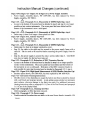
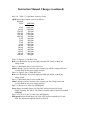
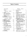
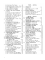


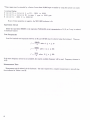
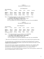
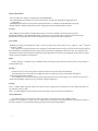
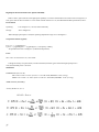


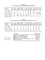

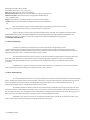


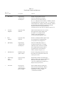


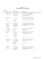


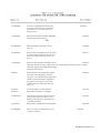
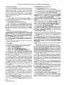

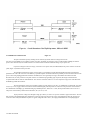


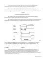
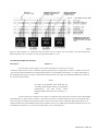

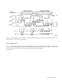
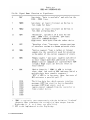


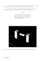
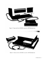


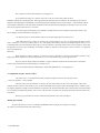

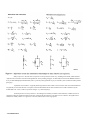

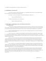
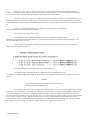
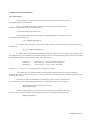
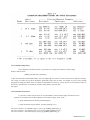
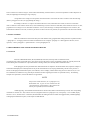
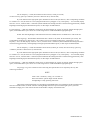


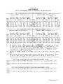
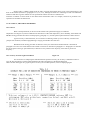


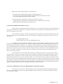
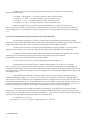
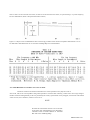
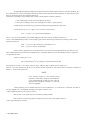

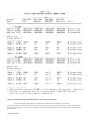


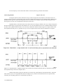


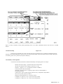

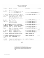
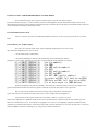
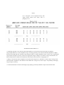
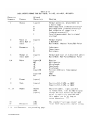
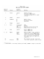
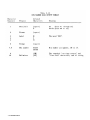


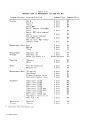

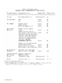

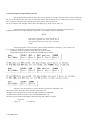

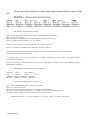

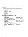
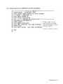
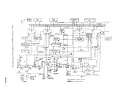


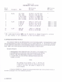
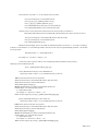
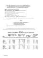
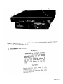

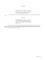


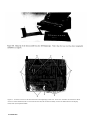

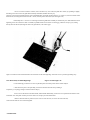


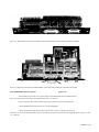


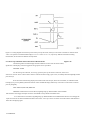


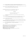


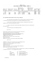
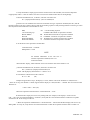
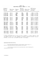


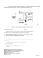
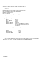
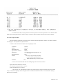
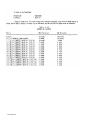

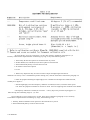
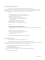

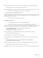
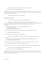
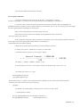
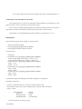
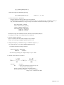


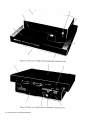
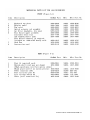
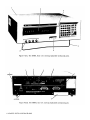
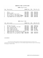


![How To Make A Noise [free version - July 2007]](http://vs1.manualzilla.com/store/data/005953668_1-8b501b70130f0a85eac6cc9cd6ff18b6-150x150.png)