1
)I\.
ATARf
GAM E S
•
Operator's Manual
,
with Schematics
...... _..... - ........
COPYRIGHT
p:m of this pullk,uion may be rcproc.Ju :<1 by any
p llo tographic or t:1ectronic proce I o r in
the form of :1 phonographic recording, no r may h be
SIOred in a retrieva l system, lr::msmiued. r Olherwise
copied for public or priv:uc use, \ ilhoul pc:rmi ~ ion
from the publisher.
10
In .Iddil ioll . Ihl' /\ .. t pro, itlL-:. fur 1":1) 011.."01 o f Millutury
J: lln:IK" !."~ uf up III 50.000 per infringinJit lr:llls:lt1jOIl in
Ct!rt;l in C,ISCS. Infringers may :Ilso have to pay co ts
and :morneys' fees :lOd f:tcc all imprisonment of up to
five ),e:lrs as well as fines o f up to $250,000 in the casc
of individual :lIld up to $500,000 in the C3SC of corporations.
Alan Games Corpor:uion will a.ggressively enrorce itS
copyrighlS against infringers. \VIe will use 311 legal
means to immediately halt any manufacture, distribution, or operalion of a copy
video games made by
u . An)'onc who purch3SC:S SUdl copies risks forfeiting
such a g:une.
or
Published by,
Atari Games Corporation
675 Sycamore Drive
Milpita , C.1lifornia 95035
Printed in the U.. A.
.'
Design. \; ' riling :l nd Editing:
Andrea Oenck 'r
Cover Illustration : Jason
Leong
...
Use of non·Alari paris or modificalions of
any Alsri game circuitry may adversely sf·
feel Ihe safely of your game. and may
cause injury 10 you and your players.
You O1!ly void Ihe g.1me warr.mty (printed on the inside
back cover
Ihis manual) if you do any of the following:
or
•
UbslitulC non-Alan pal1S in the g-Jmc.
• Modify or alter any circuitS in I,he game by u jog kiLS
or p:tns 1101 supplied br Alan Games Corpor:nion.
FCC
COMPLIANCE
TIlis equipment gcncrJlcs, u , nnd ca n radial· rad io frequency energy, and if no t inStalled and used in accor·
dance with the instruCtion manu:'!!, may cause inlerfer·
ence 10 r:tdlo communications. It has been tested and
found 10 comply with the limits for:! Cl:tss A computing
device pu"ulnt to ubpan J of Pan 15 of Federal Com·
munlcations Commiss io n (FCC) Rules, which arc deigned to provide reasonable protection ag.1 inst such in·
terference when oper:tted in :1 commercial environment.
Oper:uion of Ihis equipment in a resi<iemial area or modi·
ficltion 10 this equipment is likely 10 C3USC inlcrferenC(,
in which case the user, 31 his own e.,<pensc, will be required to take whatever OIe:Jsures may be required 10
correct tllC interference. If you s uspect interfcrence from
an At:"i game at your location, check the following:
•
All ground wires in the game me properly conneaed
as shown in the game wiring d iagram.
•
'1le powcr cord is properly p lugged into a grounded
thret:·wire outiet.
•
On g:lmes pro\.
I with an Electromagnetic Il11errer·
cnt-e (EMJ) g
pla ne, be sure lh:n the gmne print·
ed-dl'cuit bo:mls (1 .....135) are properly i05I:1I1<."<.I on the
a.·11 ground plnne and that the e nd bo.1rd is securely
inswllcd wilh nU screws in place ~lnd tightened.
7/94 ",.
Produced by the At:tri Games Tt!du1ical Publlcdtions
Dep:lnn lent.
.
WARNING
mech~miClI,
This ACI provides for substa lllbi penallies for viol:ning
ft.'Cleral COPYriKht laws. CoUrtS em impound infringing
anicles while le~al aeLion is pending. If infringers are
convict ~. coun!' t":tll o rtler de:.tnl<..1i n of Ihe infringillJt .-.n itle.,.
__ .
NON '-ATARI "" PARTS
Copyright © 1994 by Atarl Games
Corporation. All rights reserved.
_
.......
NOT I' C ERE
NOTICE
l11c game phlY, all graphic designs, this I,e chnical man·
u:II, ilS acoomp:lOying schemalic diagl"3l1ls. 1nd the dispby m:mual are protected by the
. Coprright ACI of
1976.
_-_
~
If )'OU :11\,'
still unable 10 .o;olve thc illlerfcrence problem,
plC:l~ cont:lo Customer Service at Atari Games Corporation. St..-c the inside front ('Over of tili manual ror servicc
in )'our :lrC".l.
II
a
.----------......
...
....'''.....'k."..._.•
~"."",~."""
_ _ .. ___
""'~~.
~.__
.
_ ......
Va'NAL RAo e OpfUTOa'S MANUAL <0-
SAFETY
7be/ollou..11Z8 safi.'iY prCCtltllio llS Dpp(J110 (11/801110 01)(1,-alors nud scnl{cc porsomzel. Specific u'or"i1l8S lmd
clIlItiolts will be /olmd ill I/)Is manual wblmever Iboy
npp!y,
WARNING
Properly Ground the Game. Pbycrs may receive an
ir this gmllc is not properly grounded!
To avoid electrical shock, do nOI plug in the g:une un·
til it has been inspc..X1ed :md properly grounded. ntis
g:lnlC should on ly be plugged into a grounded threeelectrica l shock
•
wire outlet. If rOll have on ly :t twcrwire Qudel, we recommend )tO U hire :1 Ii ccn~l."cI electrician to inst,lll :t
three-wire groundt!d Qulle!.
AC Power Connection. Berore you plug in the game,
be Slire thai the game's power suppl)' on :lccePI the
AC line voltage in your location. "i11C line voltage requirements :1re listed in the first ch3plcr of thi s
m:mual.
Disconnect Power During Repairs_To:1\' id electri-
•
cal shock, disconncct the g:1me from the A po\\!er before re.moving or repairing :lOy p:m of thc gamc. If
YOll remove or repair the video display, be very careful to :woid electrictl shock. High \'oltages continue to
exist even after power is disconnC(1Cd in the display
circu itry and th e cathode-rd)' lubes (CRTs). Do nOI
t uch the intcrn:.l1 p:uts of the dbpby with your h:mds
or with met:aJ ObjL"Cb! Alway:t disch:II'gc lhe high volt·
:tgt.: from the CRTs before servicing them . Do Ihis :Iftt:r
you diS<.'Ol1ncct them from the power sourcc. First, aIt3ch one end of a large, well-insulated, IS-gauge
jumper wire to ground. 1'lcn momenta rily touch Lhe
free end of the grounded jumper wire to the CRT :tnode b)' sliding the wire under the :tnodc cap. \'(tait twO
minutes :'lIld do this :18:tin.
Use Only Atari Parts. To maintain the safcty of your
At:lri game, usc only Atari pans when you repair it.
Using non-Alari p:lrts or modifying the g:lInc circuitry
may be &mgcrous, and could injure you and your
pi:lyer.!t.
IN'TU)OUCTION
SUMMARY
J:landJe the CRTs With c.1.re_ If you drop :'I CRT and
it breaks, it may Implode! Shaucred gl3ss from the illlplo ion Cl n fly six ft."Cl or more.
Usc the Proper Fus es. To avoid e lectrical shock, use
replacement fuses which arc specified in the parts list
for this game. Replaccment fuses must m:Hch those replaced in fuse type , voltage rating. :lIld current r.tting.
In addit ion, the fu se cover must be in place during
g:lIne operation.
CAUTION
Properly Auadl AU Gounccto rs. l\1;tkc. sure that the
connectors on c:lch printed circuit l>oard (PCB) arc
properly pluggcd in. The ,.'o nneCtors :lfC keyed to fit
on ly one W::I)'. If they do nOt slip on ca Hy. do nOt
force them. If you reverse ;] conne<.10r, it may dam:tgc
your game :lnd void you r warranty.
Ensure the Proper AC line l:requcncy. Vid eo
gamcs manufactured for operntion on 60 Hz Iinc power ( used in the niled t!ltes) must not be operated in
countries with 50 Hz linc power (used in Europe). If a
60 Hz machine opcr.:ttes on 50 Hz line power, the fluorescent line ballast lr.lIlsformcr will overheat and cause
3 potenti:lI fire ha7•.'m l. Check the product identifiC'.tLion label on )Iou r m:lchine for the line frequency requited.
ABOUT NOTES, CAUTIONS, AND
WARNINGS
In Mari publications, notes, caut ions :tnd warnings
have the rollo\ving me:ming:
NOTE -
A highlighted piece of inform:ltion.
CAunON - Equipment ;mcVor p~rts am be dam:1ged
or destroyed if instnlclions arc nOt followed. You will
void lhe warr.tIllY o n Atan printL-'d-circuit bo:trds. p:trts
(hereon, :tnd video di pl:t)'s if equipment or parts arc
d:lmaged Or destroyed due to f:tilu re of following in-
5111.1Clions.
WARNING - Pl:trcrs :md/or technicians em be killed
or injured if instructions :I(C not followed.
iii
_0__.__ .
I J'fnOOUC110N
<0
3
Set-Up
How to Use 'n,is Monuo l . . . . . • . • . • . • . . . . . . .1 _1
Oper.uing the Game . ... .. ................. 1.2
lnspecting the Game . .................. . .. 1.2
Control and Switch Loc:nions . ...•.• .. ..•.. .. j·2
Power on/orr Switch ..........•........ 1-2
Volume Conlrol . . . . . . . . . . . . . . . . . . . . . . .
Self-Test witch.. ............. . .......
Coin Counter. . . .. .. ..................
~
Video Display Controls ..........•.• ... .
Seuing the Coin and Game Options . ...•.... ..
Game Play ......... ...... . ....... . ......
Imroduaion . . . . . . . . . . . . . . . . . . . . . . . ..
Game Ploy. . . . . . . . . . . . . . • . • . . . . . . . . ..
One. Pla)ler Game . ........•....• . •.....
1-2
1-2
}·2
1-3
1·3
1-3
1·3
1-3
1-3
,1-4
Two-Player Game . ...•.•.. . ..• . • ... ... .
Hidden Feotures .. '" . ... . ... .....•..... 1-4
2
"'-..
PII",,u RAaa OrDATOl'S MANUAL
CONTENTS
1
!'o ... _ _ .... . _ _ _ _ _ " -
Self-Test
Troubleshooting and
Maintenance
Introduction. . . . . . . . . . . . . . . . . . . . . . . • . . . ..
Maintenance Procedures. . . . . . . . . . . . . . . . . . ..
IntrOduction ...... . . . . . . . . . . . . . . . . . ..
Cle:ming Procedure (or Coin Mcd13nisms . . ..
TroubleshOOting Procedures . . . . . . . . . . . . . . . ..
ReIYdlr Procedures. . . . . . . . . . . . . . . . . . . . . . . .
InltOductiOn .... ..... ..... . ..•. •... :.
3-1
3·2
3-2
3-2
3-2
3-2
3-2
peake", . . . . . . . . . . . . . . . . . . . . . . . . . . .. 3-3
Attraction Panel Ught Bulb .. ..• .•.•.•.. . . 3-3
POI Joystick .... ..................... 3-3
ystem Logic Assemblies . . . . . . . . . . . . . . .. 3-3
Video Display . . . . . . . . . . . . . . . . . . . . . . .. ~
4
Parts illustrations
•
Pan Ordcrlnglnformation ....... . .... .... . . 4-1
For figure and page numbers, see the list of
iIIuslrntions that follows.
5
Schematics
See the list of illustrations that follows.
lntroduaion. . . . . . . . . . . . . . . . . . . . . • . • . . . .. 2-1
Enlering and E."(iting the Self-Test . .... • ....... 2-2
Select Test Menu . . . . . . . . . . . . . . . . . . . . . . . .. 2-2
Adjust Volume . ...... . . .. ... . ..... . . . .... . 2-2
Statistics. . . . . . . . . . . . . . . . . . . . . . • . • . . . . . .. 2·3
t:uistiCS Screen . . . . . . . . . . . . . • . . . . . . . .. 2·3
More Statislics Screen .....•.•. .. .. .. . . .. 2-3
'-'
H istogro m 5ereens .... . . _ . . . . . • . • . . . . . . 2-4
Game Options . . . . . . . . . . . . . • . • . . . . . . . . . .. 2-4
Coin Options . . . . . . . . . . . . . . • . . . . . . . . . . . .. 2-5
Conltols Test . . . . . . . . . . . . . • • . . . . . . • . • . . .. 2-5
Sound Test ............. , . • . . . . . . . . . • . . .. 2-6
RAM (Memory) TeslS .•• . . , .•. .•..... .•.... 2-6
ROM Test ........... . . • .• / . . . . . . . . . . . .. 2-6
Video Tests .. ...... ... ........... . .•.. .. 2·6
Playneld Seroillng ........... .. ...•.... 2-7
MOB (Moving Object} Checksums ....•.... 2-7
Alphanumerics . . ...................... 2·7
Monitor TestS . . .... .................•.... 2-7
Color Test . ....... ..•.•.......•...... 2-7
Purity Tesl. . . . . . . . . . • . • . . . . . • . . . . . . .. 2-8
Convergence Test ....... . • . . . • . • . . . . .. 2-8
fu
Warranty
Inside back cover
•
. - ~.~-
.-- .. . .---.
~ -
. .
PI.II.tAL RAe!! OP!.lATOIt'S MAto'UAL .0
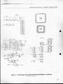
Figure 5·1
ILLlJSTRATIONS
Figure 2-1
Figu re 2-2
Figure 2-3
Figure 2--1
l~'igurc 2-5
Figu re 2·6
Figure 2-
Figul'l;: 2
n~urc 2·9
•
Adjust Vo lume Screen .....•..................... 2-2
latiSlics Screen .................................... 2-3
More St~Hi slics Screen ....... .... ............... 2-3
liislOgr.11115 reell ............................... 2-
VldL'O ,.~.,
Figure
Figure
Figure
Figure
Fig ure
4·1
4·2
4·3
4-4
4·5
Figure 4-7
Figure ~5
Figure 5·6
~()uncl Tc ...t ~l' 'n ............................... 2-6
Figure l-II
2· 12
2- 13
2- 14
2·15
2· 16
2· 17
Figure 54
Game Options crecn ......................... 2-4
in Opli ns ~"'en ........................... 2-5
Gomrol-: Tl.'Sl : 'rcen ............................ 2-5
~h:I1It1ry "","~b . fl:en ...........................
Figure -6
•
Select Tcst Menu Screen ...................... 2-2
FlgufC 1- IU
Figure
Figure
Figure
Figure
Figure
Figure
Figure ~2
Figure 5·3
2· 7
Pla yfield Scrolling Screen ..................... 2·7
MOB Checksums Screen ..................... 2-7
Alph:lIlu nlc rics Test Screen ................. 2-7
COlor Test Scree n ................................. 2·8
Purity Te t Screen ................................ 2-8
Convcrgence Test Screen .................... 2-8
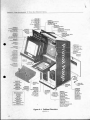
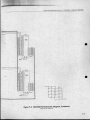
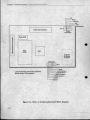
C.1binCI Overview ................................ 4-2
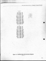
Po wer Supply Assem b ly ...................... 4·3
Over/ Under COin Door Assembly ...... 44
Board
Sl~l ck
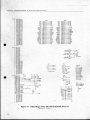
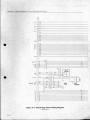
Primal R.'ge Game (GO PCB
Assembly Schematic Diagram ............. 5-2
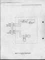
Coin Door Wiring Diagram ................. .5·7
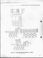
GT24MS I'C13 Assembly Sche matic
Di3gra.m ................................................ 5-8
JAMMA Filter PCB Assembly
SchematiC Diagram ............................ 5-14
l)rim:lI Rage Game Wiring Diagr.ull ... 5-16
CI·131 _2 (CI\ GE" Audio) Coord Block
Oi381'3m .............................................. 5·18
'fABLES
2-6
rct..:11 ...... ........ ................
ISTIIOUUCTION
Table 1· 1
Game pecifiC'.Itions ............................ ' ·2
Table 2·1
Table 2·2
Table 2·3
Summary of All Self·Test Screens ....... 2·2
Game Option SeUlngs ......................... 2-4
Coin Option Seltings ........................... 2·5
Table 3-1
Table 3-2
Table 3-3
Geneml Troubleshooting ................ ,... 34
ROMs and RAMs Troubles hooting ...... 3-5
Voltage Inputs and Test Points ...... ..... 3·6
Assembly ........ .... ............. 4·6
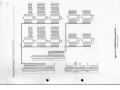
Primal Rage Game (Gl? PCB
Assembly ..... ......................................... 4-8
GT24M8 PCB Assembll' ..................... 4- 15
JAMMA Filte r PCB Assembly ............. 4- 17
,
.'
"
"
•
r
CHAPTEH
1
•
How to Use ThIs Manu.,.
.
•
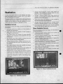
T
HI ' MA l
and
AI. I wrincn fo r operal r '
s~ rvi ce
per ·on nel. II provi les in-
formation for cuing up, pb)ling, Ie
t-
ing. and maintaining your Primal Iloge- game.
Primal Rage is a one- or Iwo-pla yer headlo-head fighling game fea turing f"nla I' rea-
elf-l est.
hould regularly
l esl Ih e bo,,,ds
and conlro ls wilh
Ihe self-Iesl 10 keep your
game.; in peak condilio n and at lOp earnings.
haplcr
lure and slate-or-lhe-;]11 ~l nill1ation .
You
+
3 conta ins sever:ll Iroubleshooling ta-
Chapler I of Ihi ma n\:10 I contains SCI-UP
bles, plu maintenance and repair procedures
and ga me I Ja y inf rmali on . • Chapler 2 con-
fo r Ihe ga me com po nent. If you have prob-
l ain a des ripli on of Ihe se lf-Ie ' l
procedures :lnd opl ion sellings.
The
sell~le
I is im pon:1I11 in Ihe Pri-
mal Ib 'e
g:l!ll~.
YOli
~I n tf 1I-
kms wi th your ga me,
1I.
e thi chapter to
trOll-
bleshool and repair il. Oe sure 10 perfo rm Ihe
preve ntivl: maintenance ta sks to ket!p your
game in good condition. + Ch:'1ptcr
conta ins
prinlcd-c'ircuil
Ihe: i1lu,[r.l1ions and I' 13 pariS lisls. • Cha pler
bO;lI"(ls ( I' Us). lI1:1in circui ls, and
; contains Ihe schemalics for ;111 Ihe PCOs :Inti
bh.:.< hool
Ih<:
controls u "ill' th e crcens in th e
all thl.! wirin -, diagrams.
•
,
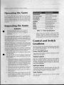
Operating the Game
TO opera l e your game for 1I1.Iximum income . you
should rt!~ul:lrly run the self'It!!)1 :md check the conlrol
wil h lhe Conlro l "l'e.:.1:md SOund Test in the self-test. By
using Ihe l)e1f·lesl regularly. YOll C'J Il fll1e1 and fix prol>IcntS iml1ledialcly. '111is lets you keep your g:lI11C in l Op
condilion.
Inspecting the Game
WARNING
•
To avoid electrical shock. do nOI plug in
Ihe cabmel un/ilil has been properly inspected and set up lor (he line voltage in
your area.
--l:: tbinci .:.hould be
l'OnnCC1~--d 10 a groundl.-d lhreewire outlet on ly. If you h:t\'c only Iwo-wire oUilets, we
recolllmend thaI you hire :t licensed electrici :1I1 10 in·
stall ~round(.."(1 outlCIS. Pla yers c:m receive :111 elt"Ctric:aI
l)hock if the l.lbinel is not pro !,x:rly grounded.
111is
Make note f the power o n 'umption when you set lip
Ihis g:II11C. so Ih:1I you do nOI Qvcrlo:1d your electrical
circuit. ce T:lble I-I for the power consumptio n and
the olher impon.'trll spcdlic uion of this game.
Insp<:a your Prilllal R!lge g:lm<: carefully to ensurc that
the game is com plete :lIld was ddivered to you in good
cond ition. 1n:.pc..""Ct Ihe cabinet :lIld sc:n as follows:
. 2.
I. E:'(aminc the exterior o f Ihe cabinet for denIS, ch ips,
or broken P:U1l)·
Open the lowe r rear access panels. Unlock !lnd
open Ihe coin doors. Inspect the interior of the cabinci :as follows:
:1.
heck Ih:1I a ll plug·hl cunn(.'Oors on the clbinet
harnesses are firml y p l u ~gcd in. 00 nOI force
conncclo rs IOgclher. 'I11e co nn ~clOrs are keyed
so Ihcy fil o nly in Ihe pro per orientatio n. Arc·
\le r~ed CQnneclOr C:ln danhge a printed· ci rcult
bo:}r<:i OlCO). '111is will v<?icl your warr:tnty.
b. Ensure t ll:1 1 :11 1 plu ~· in illtcgr:u ed circuits o n
c::.lch I'CU :Irc flrml)' plUggl..d into thl'ir sockets.
c.
In~ pc l i Ihe powcr cord fo r :lOy eu lS or dcnt~ in
the insul:llion.
<.I. Inspect the power su pply. ~'I akc sure that the
(;orrect fU5.es arc in~t:llled. Check that...lhc harness is p lu gged in ('o rrcctly. Che k Ih;1t the
green ground wires :trc l'Onneoc"<i.
1-2
Characteristic
........__ . ... ....
Specification
Input Current
3Ampsatl20V
Line Fuse Rating
3 Amps at 250 V. slow blow
Line Voltage
t02 to t32 VAC
Temperature
5' to 38' C (37' to 100' F)
Humidity
NOIIO exceed 95% relative
Width
25.25 inches (64 em)
Depth
33 inches (84 em)
Height
7t.751nches (182 em)
Weight
3251bs. (148 kg)
Table I-I Game Specifications
c. Inspect o lher suO-assemblies, s u has lhe vidc.."O
displ:lys, controls, prinled·circuit boards. !lnd
spc3kers. Make su re that they :ate mounted securely and that the ground wires :tre connccrcd.
Control and Switch
Locations
All o f the l.'Ontrols arc 100000ltcd on the back of the cabi·
net o r behind the coin doors, 'rhe fo llowing describes
the Ioc:uions in mo re detail:
Power On/Off Switch
The power on/off switch is 1000tcd ncar the tOP of the
cabinet lower rear p:aoei.
Volume Control
There is no volume adjustment knob o n ;t ny PCB in
this g:lI11e. Inslead. volume is ;tdju sted in Ihe self· lest
so(nvarc. '111e aur.tct·l11odc 3nd game· play volumes C',J1l
be :l.djusled scp:trme1y. nefer 10 Ch:1ptcr 2 of Ihis manu·
al for more information.
Self-Test Switch
To perfo rm the self IcSt, open Ihe upper coin door 3nd
:IClivatc the sclf·ICM swit h mounlc..'1.1on :t bracket 1000t·
(:d on the inside left panel of the ga1l1e c;lbinct.
Coin Counter
'nIe coi n coun ter is locmcd below the t'Oin box. ins ide
the coi n door.
-"
.....
- -- ~
...............
---
_.
Video Display Controls
Thi .. game powidc.. :u.:(.'c~ 10 "ix of the 010;,1 important
vidco db-phi)" cont rols - veri kit l and horitonl:l! po!lilion, verlil.,,:ti ho ld , VC rl it.-;ti si"..:. bl:tck level. and contr.tSt. To ~:tin :ICCc.;SS tu the \ ideo dbpJ:ty (:ontrols, n.:move the rt!Jr p:lnd . The conlroi knobs :tre mounted
on thc insiue of one of the ide p:tncls.
Setting the Coin and
Game Options
111C Primal Hage coin and WHne oplions :arc el in Ihe
__ self-test. Refer to Chapter 2 for the recommcnded ;,Ctlings and lhe procedure for selling the opljons.
i>rim:1I Ra~e fe:l.Iurc", :t
four- butlun
on tro l
th:u :tllows "po\\ er- hu~
to be mapped 01110 both
the t p :and bottol1l lUll n p:tirs.
To execute :,pecia l moves. pla)' c rs
must press :lI1d hold button combina·
tions while moving the joystick ~tt the sa me limc, in a
method Ihal differs from st:lI1cl:trd fighting game can·
trois. This allows for:t diversil)' of regubr hits while :H
the s:lIne time providing a new way of execuling speci:tl moves. 13ccau~e of thiS feature. Prim:tI tbge controls allow for very nuid combination pOtenti:tl. Ad ·
v:lnced pbyers will be motiv:Hcd to learn all of the
moves to develop the best combinations, providing the
driving force for high·lcvcl competitive action.
Game Play
TIle game offers twO
•
b~sic
typc..-"S of play:
Game Play
•
l11is section descrilxs Ihe fe:tlllrcs 3nd play of the Primal n:lgc ga llle.
One-player g:lme. The player must defe:u :111 st!\'cn
opposing characters 10 gCI to lhe Bonus Hound and
Final BauJe.
•
game. Pl3yers b:mle each other for trophies. hum:ln followe rs. :tnd World Domination.
The wi nner is the player who captures th e mOSI
'"globes" :tnd amasses the mOSI followers.
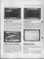
Introduction
Prima l R:18l! is :l he:ld-Io-hc:ld fighting gamc fe~lIuring
St!ttc-of-t hc-:an slop-motion :lI1imated char.tClers. Pl:'tyers hoose from :,evcn diffcrenl gi:ml ElI1t;:lsy creat.ures
in an aHempt to domin:lle the new "Urth: using fighting m o\'~. powerful ·secret- move . m:lStcrful combo
hils :tnd graphic finishing ~cq uences to climinate their
opponcnt.
Primal R:.Igc utilil£S a proprietary new stop-molion :1I1im:lIion leehnique thai provides reali lie and Iifc· like
eh3r.tCler mOl ion. tn addition to state-of-Ihc-:t rt graphics, Primal Rage features the new CAGE "1'Ola l Immersion Audio" syslcm. providing gre,3t stereo sound that
p unctu ates high -i mpao g:un~ play.
Due to their gre:1l
size and speci:t l
POWCl's. eaeh of the
seven
~lV:1il:tb l e
characters in Primal
Rage is worshipped Tolallmmersion Audio
as :1 "god" by the su rviving hum:lI1 s of Urth. A~ pl:lydS go through the
game. they :lm:ISS :lddi l ion~tl followers with every viaory. Followers t";ln :tlso be c:lI~n 10 r(!pleni!th !ttrength. if
needed, but lhisi.s 1"C".llly :1 1ll:lIter of pcrsonart:l!ttc.
Two~pl3ycr
One-Player Game
The player must defe:u all seven opposing dl:l r:lclers.
one at a time. in order 10 get to Ihe Bonus Hound and
Final Baulc. Each pl3yer and opponcOi char-ICIer h:ls :1
'" health bar' 3t the tOP of the screen thai is reduced
whene\'er :t damaging hit is made. If:l player's he:1lth
bar is reduced , huma n foll owe rs Gin be e:llcn for
bonus hcalth. E.'lch opponenl dcfc:ucd will result in:l
new territory being awarded.
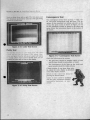
FInIshIng Moves
When an opponent character h;15 lost :til its he:lhh :lI1d
is sl:tnding there dizzy. the ch:u:l Icr is in il s "dea th
lhroes" and is about to die. The "finishing Inove" is a
specia l bulton combination (d ifferent wilh (.'~lC h char:tcler) that C ln be used 10 "finish ofr- an opponent while
it is In its dt."":tth throes. sing:l flllishing mo ve demonSt.l':lh:S technique and ~cner:llcs excitement , but. Illost
importantly. :lffcelS the SI.:HllS of opponen t Ch:lr:H.:terS
when Ihey return during th e Fin:11 U:IIIJc. Pl ayers will
be lllolhO:ilcd to 111:1 ter :III of th\' finishing moves in order to pl:aY~1 perfect game.
/-3
e
a .·. ____....
•
....
Bo nU5 Round and nndl &title
Hutndll Followers
After dcfeating :111 sevc n opponC:llt5.
the p!:arcr is awarded :1 Bonus Round.
durin~ which points :Ind bonus henlth
cnn be collccte I by snacking on human
followers . AflCr tht! OOI1U Round, the
playcr moves to the Fin:d Battle, during
which all of the player' s foes must be
quickly v:an(juishcd o nce :tg:lill, o nly t.hi s
time With a Iwist: the player has onl y one
he:'llih bar plus bonus health, :tnd each opponent c.:haractcr will return eilher :1S a nor·
mal character or :IS :I ghost -like character.
Any char:t<.1er that Ihe pbyer did nOt eliminate using a
finhhing mo\'e during the regular rounds will come
hack as a normally hcalth)f char..! ler. Characters on
which :1 player successfully cxecuted finishing moves
will return as ghosts that suffer more damage per hit
innictL"<i.
Human followers are awarded for various accomplishment in the game. The number of followers awarded
depends upon how well ~l phlyer fIghts, including att:lck combinations, dam:!ge to the opponent, use of fin·
ishing moves, and f:tt:llities.
Any pbyer wh has won the Final Ballie is rewarded
wiah the slO ry lint: for th:n characte r :lIld a special
graphic picture depicting th:1I dl;H-:tCter's life :Irtcr they
have clplUrcd Unh. Players who lose all of their health
during the Final Bailie have the opportunity to contino
uc the game by adding more coins.
During:t I -p l:tyer game, :tnothcr player can challenge
the current player by inscning coins in the unused side
of the game. '111e origin3) p):lyer now competes against
the new ch:lllenger.
Two-Player Gam e
I'bycr.. b:mlc each other in ;1 match decided by winninjot twO Oll t of three rotJntl... A trophy :tnd hum:'" fol ·
lo'\\cr :trc :lwarded (0 the player who wins each
rOllnd, :1I111 :t new terril ry on the globe is awardc..oU 10
the \\Iinn!.!r of lhe match.
.'
,
1-4
Sudden De.1th
If the tWO players are lied at the end of the third rollnd
(s;t me number of trophies :lnd both pl:tyers still alive) ,
then a Sudden Death round is stanc.--d. At the beginning
of Sudden De:uh, the timer is reset to 20 and phlyers
receive full health bars. During pl:1Y, e:tch pbyers
health b:lr will be reduced by time :Ind hits. If Sudden
Death ends without a victor. both players will die and
the game will end in a tie .
World Dom/mttlon
In order to adlieve World Domination, a pbyer must
win 311 seve n territories on the globe. When this is
:lchie\,ed, the pbyer will be ;Iwarded a globe and morc
human followers. There is no limit to the number of
globes ~lw3rded in 3 2·playcr gallle. The winner is the
player who cap(ures the most globes and amasses the
mOSt hUlllan followers.
Hidden Features
Ch.d/ense Game
•
:..
..
Many hidden features are included in Primal ltage.
ornc of these fe:uures are activated by diffcrent joystick and button combina tions. ome !'Ire skill-specific ;lI1d some requirt:
coo perallon between
pb)crs. i\lan)' hidden
fC:llures depend upon 'w hich
chara ter is being played ,
'w hich backgrou nd is in view,
or which co mbin:tti On of
moves is used .
-. .
CHAPTER
2
Introduction
•
U
E THE PIUMAL RAGE'· self-test
10 check the condit ion of the
game circu itry and con trol s.
You will ee the elf-test information on
the video display and hear the sound
te t information through ule speakers.
You do not need any additional equipment to perform the self-test. perform-
,
.'
the self-te'( when you first set up the
game, each time you collect the money, or when you suspect game problems. Thi ' c hapter sh ows th e
screens in th e se lf-test and explains each of the
tes ts. 'rhe screens
and-explanations are arranged in the
oreler they appear in thc self-tcst. Table
2-1 list - all the self-test screens.
__-
... _..... _.....
Entering and Exiting
the Self-Test
...
se lected teSI by pressing the left player upper left
bunon.
J.\,lIll\: .. ~·II ·II,..· ..t .. \\ iu:h ,.. hx.:;IIL"C.I I~ h i nd the l'om
dt N II 'I urnlll~ It un t;;tU~~ Iht.' -.('r\.ocil Ie) I..'llIcr the :o.t.' lf·
11..'''1 IIlt)(.h: I>OIll~~ ) dhpl.I) :> Ihe xh..->t.·t TI..'~ mCllU; ~I;.'
I'I).!u n · 1- 1 l\1t the .'\(·If· tl..' ..1 hy turning o lT Ihl..' :-elf-te .. ,
Tht'
..\\ Ih, h
.n
.10\
tunl..'
\ 1 Ihl.' hunolll 0 1 thl..' -.c.'II-llo'''' ~·I\.",,·n ) ou 11I;1} rmd th.1I
111\' \ If, o r 0" \I,..·r-.iem." ..hem 11 in 1111 .. 1Il.lIlu,d :If!.,' (ii ih.'rl.:1l1 t"tIll \ uur ),t.II1IC Am h :r"lon t.hnl,..·rl..'lll"t.·.. an the
.."ll\\.Ih' .Irl' Unlll1l)OIUIU
• Select Test Menu
ChO<>* which lest or screen you want to St."C from this
menu. 1'ho\\'n in Figure 2· 1. I\love up and down the
menu b}' moving either jo},slick up or down (or by
pressing the left pl:lyer upper right bUllon) . Stan the
Select Test Menu
Adjust VoIlNtl6
StatistICS
---------------
figure 2-1 Select Test Menu Screen
Adjust Volume
Adjust the volume o f t he g3me usi ng thi s screen,
shown in Figure 2· 2. Pollow the instructions :n Lhe bottom of Lhe screen to restore the old volume level or to
sa ve the new volu me :Jnd return to th e se lect test
menu.
,11 ~UC
~
If
S!lh'~hcs
~!our;.dlls
Gal1~ OpialS
COot> Gp' 'IS
•
CcnIJO/s T"",
So/Jrld T8SI
RAM /Afsmoty) Tests
idooRAM
V<Jeo RAM (qUCk)
c-RAM
WOIIungRAM
WOIIung RAM (qUCk)
NlRAM
ROM Test
Vdeo Tests
Playfleld Scrolling
MOB (MovIng Objects) Checksums
Alphanumerics
ftAonttOf Tests
c-Test
PuntyTest ....
Convergence Test
Table 2-1 Summary of All Self-Test Screens
2·2
-.
... . . . ..
Figure 2-2 Adjust Volume Screen
111e soft..:vare continuousl y plays music 10 allow YOll LO
:ldjuSI both the g:lme and 31lr:1C1-mode volume le\?cls.
TIle word GAMb· or ATI1lACI' nashes to show which
of the twO volumes levels you :Ire :Idjusling. ~'I ove ei·
Iher joystick up or down to select either one. l1lC atlract-mode 1lolume level has four tel's: mUl.e, 113. 2/3
or full volume level (these are rractions o f the game
volume level).
~,,~_.,_ .-
~"'":...
• • •, ••,,"'. . . .
Q.. . . . . .
•
• - -• •
~ -.-.--
~~~ .
Va •.MAL RAGE OPB...,ro.'S M":OUAL -0-
CIIA .. TI!.It Z -
SUf'·Trsr
•
Aver:tge New/ Continued I Player Time shows :m
:I\'cr:tgc of the number of minutes playc..-d by one
pbyer in a new or COlliinued game.
•
Average I Playcrl2 1)l3yer G:tmc Time shows :tn
avcrnge of the number of minutes played in one
g:lI11e by one or {'tvo pbyers.
"IltC g:unc st:llist ics :lrc colleCled fro m the J:ISl time the
sl:tt iSlics were dC:lred. Follo\v the inSLnIClio ns ;It the
•
To t~ll Coins shows the number o f coins counted in
bottom of the screen to clear the latist ics or 10 ad\':InCC to the next Sl:ltislics or hislOgr:lnl screen.
•
Statistics Screen
• I)crccmagc P1:ty shows the ratio of game pl:ly ing
Statistics
sc the inform:ltion 5ho\\,11 in the St:uislics and hislogram (bar gl"':lph) screens to keep tr:lck o f your game
use :lOd l11:lx imize you r profits.
'Ole IrHisliCS screen (see Figure 2-3) lists Ihe following
inform:ni 0 :
•
Lefl Coins shows the nUIl'\bcr of coins counted in
the left <,,-Oio mL"Ch:tnisl11.
•
•
Right Coins shows the number of coins coun ,,,-od in
the right (:oin Illcch:mbm.
both left and right coin mechanisms.
lime 10 total time the game h3.5 tx-en turned o n.
More Statistics Screen
nle More
•
I Playcr/ 2 PI:tyer Games shows the number of
8:II11CS played by 1 o r 2 p1:tyers.
•
1 Pbycrl2 Pl:tYCf Continues shows the numlx:.r of
ga mes continut.:d by I or 2 playcrs.
I Pbyer Finishes 'hows lhe number or games finished in I -player g;tmc mode.
Challenge Games shows the number of I -player
g:lIncs imCmJplCd by ~ 2nd· player Ch:lllt:nge.
mechanism).
• Idle
Minutes ::.hows the nurnb<:r of minutes that the
game
•
W:,IS
idle
;lIld
nOI being pbp.::d.
I-Player Mimnc:J'2-PI:lycr Mimlles hows the tw mber o f minutc!) lh:tt Ihe g:Jlllc was pl:lycd by o ne o r
two pklycrs.
• New Game MinuteS shows the number of minutes
played :I flcr Slarling
~I
nc\ gam .....
• Continued G;lIllC MinUlC.s shows the
number of
minutes pbycd :lrlc.:r continuing a !pille.
•
EEI)J{OM Error Count shows the number of errors
counted in th' ef'..I ... lhlc menlory. If rou h:I\'c :m
crror COUll! . Ihl.' .. t.lIl .. tl~~ lIl:!r he \\ ronJ.t. If ) 'OU
S t~listi cs screen (sec Figure 24) lists the fo l·
lowing info rmation:
AliX Coins ~hows the number of coins manually
:Iddcd b)' Ih e oper.nor. (nol in se rt ed In to :Iny
or
Aver:lgc Time per Coin shows an average
the
number of minutes played for every coin coul1lcd.
•
•
•
Sudden OC:llh5 show s the number o f tic games decided by sudden d('.;'nh.
•
Final 13alllcs sho ws the number of times ~l single
player :1chievcd :t Final J3altle.
•
Fin:t1 Continues shows the number of credits used
during :t Final Battle.
•
Oll)," I"ll'Ulh h.I\,-" ...·rull .....·uunh.:d for .. \.'\1.:1.11 \\Cl·k ...
I ...·pl.ln.: th ...· U ' JlI(
~.lInc
•
\1 .11 221 1 on till' IJrnrul ItlJ.l.t.:
I'CIJ
Figure 2-4 More Stat istics Screen
Figure 2-3 Statistics Screen
2-3
Histogram Screens
'l1h.: lIi!>lo~r: ll n., :-t."fCcn b :l menu Ih:1I lets )'Oll dbpl:!.)'
unc of Ihn..'C 't(lcc,;n ... (-.c..'t! Figure 2·;). TIICM." show \";IrilUI' hOli/olll.11 h.tr J.!r.lph ... for lound 11I1I~. Ill:llt: h lime .
. 1111,1 ,,'k'( lIt.n" 11(.." "h.II .ll Ie..'r
in:'l rU("1ions ~hown ;'\1 the botlom of the screen. 111(.'
g:um; option:" with d cf:m lts. are shown :mc.J explai ned
in T:lble 2·2.
•
FIgure 2-6 Game Options Screen
FIgure 2-5 Histograms Screen
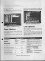
Coin Options
Game Options
Check and elcct the coin options on this screen.
::thaw" in Figure 2·7. n,e screen shows the f:lclory def:lu it scu ings 111 green.
Check :md :-.\.'Icci Ihe g:lInc: options on thi scree n,
~ho\\ n in Figure 2·6. 'nlC sen..'en shows the f3ct ry de·
f.lull ~Ulll.c' in wecn ,
To IlIU\"\.' tluough the opt ions. 10 ch:lIlgc or ~ I \'I,; thc
\l:lIIngs. or 10 rcturn to the select tCSt menu, follow lht.:
•
Game Option
To move through the options, to dlange or save the
seuing.... or 10 relurn to the selc...-'CI l eSt menu, follow the
inSl nJCli 115 shown :It the 1>0110111 of the scree n. 11lC
coin option scllings. \Vil h dC(:IUII:" :Ire shown :lnd ex-
pb ined in Table 2·3.
Available Settings
Explanation
Game Difficulty
Easiest
Mosl Difficult
Medium V'
P,ovtdes a choK:e of SlXleen levels of game
d.flicully
Game Goro
NoGo<e
Full Gore 01'
PrOVIdes a chotce of IwO levels of gory effects. No
Gored,sables all bkxXl and finishing moves.
Censor Strictne ss
Easygoing
SlriC I t/
Strict seIling disallows cerlsin vulgar leuer
comblnauons in the high score table and in the top
score display.
Demo Mode
Yes
No 01'
In demo mode, characters never die. This selling
should be used for demonSlrallons only.
Restore Fa ctory Coin Default
Yes
No v
Relurns COIn ...
Auto Reso t High Score Table
Yes V'
No
Automatically cit:
periodically,
Reset High Score Tablo
Yes
No V
Clears the high sco·
Yes
No 01'
Restore Factory Delault
J high SCOfe lable
Ie the nexi time you start a
game (one tme onl
Relurns aU game S4
tI' Manufacturer's recommended settings
Table 2-2 Gam e Option Settings
2-4
to faclory delault.
10 laclOty detault.
·.l'II\IAl R"OI. OrfR.\T . '), ;\1.\,. Al
Coin Option
Free Play
Discount to Continue
Game Cost
Available Settings
No v
No v
0)
C II Al' nUI 2 - S£LI'·"r.ST
Explanation
Yes
Leis you choose free play 10 demonstrate the game
Yes
When sel to Yes, thIS option reduces by 50% the player's COSI to
conllnue a game (atways rounded up to the next full coin),
1 coin 1 ereCh!
The number of COins required lor one credll.
2 coins 1 credit V'
3 coins 1 credit
8 COinS 1 credtt
Bonus for Quantity None v
Buy-In
2 coons gIVe 1
3coms give 1
3 COIns gIVe 2
---
Lets you choose from varoos kinds of bonuses or no bonus.
9 COIns gIve 2
9 coins give 3
~~~--~~--~--~~~~----~~~---.
1 coin counts as 1 coin II'
The number of coins each COIn counts as In the tight coin
Right Mech Value
1 COIn counts as 2 COins
mechanism.
1 COIn counts as 7 COIns
1 COIn counts as 8 COU15
Lett Mech Value
1 co.n
counts as
1 COIn t/
1 COIn counts as 2 COIns
The number of COIns each coin COUnts as In the left coin
mechanism.
I COto counts as 7 COIns
1 com counts as 8 coins
...... Manufacturers recommended settmgs
Table 2-3 Coin Option Settings
•
Figure 2-8 Controls Test Screen
Figure 2-7 Coin Options Screen
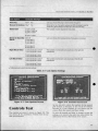
As rOll usc e:lch I..onl-rol. the nUI11I)C~ for the jOY:'lil"k
potS incre:lsc r dt."Crc3SC!. or the reo ;\!) ror :-witl.:hc:hecome Os,
the change:, do nOI :lppe:tr on the
!'olTCen, cTlc(.'k the controb :111d th("ir wiring,
Controls Test
' 111C
comrob Ic~1 ~t:rcen j:.. :,huwn in Figure 24:1.
Ir
' 111i!)
, h:st checks :111 thl: pll~ hhtltlUn :-wi(chl..·~ and the joy~
Stick I>otcntiomclcn;.
1'0 rl.':o.et the jOY!llick pot Iimit:-, 10 c:h:mgc or !i.:1\'C Iht..'
!')cllin),.l,:), or 10 rel urn to Ih'-..' :.ckl.:l 1..::.1 11I(.'nll, lolluw Ihe
instrll~l i(Jn,.. shown at tht.' bonulll of Ihe ~cl'ccn.
2-5
ellA ..I ' . 2 _ :' I I I -T[~T
<>
1'.1\1-\1
H".r
•
..:·,.:..::t•.::•.:.,.::.:.,_ _ _ _ _ _ _ _ _ _ _ _ _ _ _ _ _ _ _ _ _ _ _ _ __
O,.~.:.::.r:.:o::
•
I'r..· ....... lIul buh/the 1\.'1t 1,1.1\ ,,'r up!"...:r ri~11l bunon 10
hom th ..' ",mimi ... 1t.· ...1
.." II
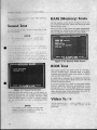
RAM (Memory) Tests
:,C thi!) selection SCK"Cn. s hown in figure 2· 10, IU run
:my of the five RA~I lests. These tests check Ihe 1lA.~1
chll 111 v:uious w:tyS.
Sound Test
I ~. Ih .... ">Cll..'uion !)Creen. :-hown .n Figure 2-9. 10 lest
Ih ..• ...~Iund htl.lrd
When )'OU turn on the power, the g:l1ne :lutoll1:uicall),
nil\!) through thc random-acct:!lS memory (RAM) I\.!St.....
Uefcr to Ch~lptcr 3 of this ll1:mual for morc delalls.
N O TE
8(/
Jilt
(,(1
tx
Ie!ct
., ne IIIslalled and
,.,erform Ihls
qt<1
JIl r! It
'1~.
, I
•
." Iii, ,!lid,,, 1\( ,\1 ...
t
I
I
dd\'llllll1l' II
PI I Ih "\
I
II,
\lIdl'
11111
\ lI\h.. <.h\'\ ......lllll...
tilt
.111 IllIn' .. p.... I~\·r ...Ih· \\UI~IU).:
Ill,' 'I" .11..\'f ".."
l 11\" " ..WII
I, ..,
\, Ith Ifl.'l
o.
,III Ilk.' ,II.." I..
n' dl'pl.n"-,,l III \\ 1111\' II .111\
Iltt'm .. 11'1\\ I\'d
11111"'1
\.~I h,I'\ .11".>1111 III \\111t III,' ,1I","lI1ln I'f
I{I I'\<' II .111 1(1 "h .11\' h.I,I.
Ih.., \IRlllt f\ 11 ,I
'-I11~h ,,1,,·\ l., ... UII1 ... h .ld.
Itll IIl1pntp..-r I«HI
It I..
"""",1
,Ii,-,"
figure 2-10 Memory Tests Screen
~ ·.IIII1).!
ROM Test
This scree n displays :JnY nO"1 crrors by :,howing a
non· zero numlx:r "ncr a p:lnicu!:tr item, A properly
working board should cause your screcn to tli play
only O!. in thc righl column.
If :I ROi\! fails, :t message: m:ly be displayed, Ilowc\'cr,
depending on how bJd the RO;\I error is, you 1ll;IY nOI
be able 10 enter the self-test .
•
Figure 2-9 SO\l nd Test Screen
\\ 'hen rou :,cICCI the: peakcr Tcst, )'OU will hear a Sf!'Iucnle of li1ft;!c sounds, with ";" different ound coming
rrUin e.lch speaker: the lefl :,pc:ake:r \vill emil a frog
"'-HlIlt!. Iht.: righl s[X':tkt.:r \\iII emit ;1 \\'oOl ~ln 's scrC:IIlI,
.tntl Iht.' ~ub-\\'ooft.:r will .... mil :t booming. footfall
If you 1I3\'e ;t RO~I error, chl..-"Ck the four nOM!) labck.-d
PGM_ I.L. PGJ\CI..M. PGM_ M. 3nd I'GM_ U :U 24l
through 291.. on the Prim:t! Rage game PCB, Check
Ihest: IOC:lIions for bent pin ~ or incorrectly inserted
chips. Also see Table 3-2 for information :tbout Ihe 10otion:" of the ROMs and Iheir funCtions.
Video T
s
'<o(Hlllti
M' Ihl'\
Icrmine Ihe (onti.tlon
NOTE
The footfall sound commg from Ihe sub·
woofer tV/II also be heard 10 a cerram ex·
tem from Ihe olher IIVO speakers
<---
2-6
sclt.."C1ion 'iCr\
~:II11C I'
B.
luwn in Figure 2· 11, 10 dcIhe video circuill ' on the
Figure 2-11 Video Tests Screen
Figure 2-13 MOB Checksums Screen
Playfleld Scroll/ng
Alphanumerics
TIle pl:tyfit:ld :-;croll in!! 1l.'!)1 j .. :.ho\\ n in fl~urc 2·12. To
;,croll the pl:l}'fidd (:o ntllluoll!Jly in :1 hori7onl.11 or vcr·
tlcil dlrctlion. InO\'t: lhe 10) ;o.lick in Ihe com.. .,ponding
11,e 31pbnuIl1eric It:M is shown in Figure 2,1~1. To
p:lgc (~ro ll ) Iht: :,<.;rccn up/ down. mo\'e the jO),Mick
accordingl)'. I f Ihe M'rec:n im:lge.: dOl'S not move, or :'1)'
Ix:a~ different from thb f1gun.:. rou h:I\'t::l problem
in the :alphanulllerlc circuitry :11 I(x::lli 11 221'/ 1{ on the
I'rimal R:lge g:lmc PCD. To return 10 the ~clect le:,1
menu, follo\'\I Ih" inSlruction:, ,hown :Il Ihe oonorn of
direction. 1\I:-.kc SUft:' th:U Ihe pbyfield :,Crt."<:n l!:t dC:l1l
:lnd :,erolls smoothly
:lC~
the
SCTt.'cn .
If the ~ rt.."t;n im;lge doc lUll movt:'. or :tpp<::lf'S dlffcr\.'m (rom Pi)!,urc..' 2- 13. rUli h:l\,c :1 problem If) thc pl:lyfidd tlrc.': Ullry :H loc.lion .. 1'S "\-2 N on the Prun:t1 It:lgt:
;':.Ullt' I)CH To n .:I UIIl 10 Ih ..., :.1.'11,.."(.' ( le.,1 l111'nu. follow
tlll' lI1'tnllll("'''' .. Iltl\\n .l!tllt, I'OIIUlll u lllh-' ,,-n.: '11
Ihc
M~rccn.
•
",
,
, "
.:
• • •••••
.
.. ,
", " ' ;
~
Figure 2-14 Alphanumerics Test Screen
Figure 2-12 Playfleld Scrolling Screen
MOB (MovIng Objects) Checksums
111<: fir ..,
IOU IC!>I sc..' rccn l.'xaminl.':t the dll:(.· k~um:. uf
the ,\1 H U ~I ... If Ihe Chl'~ k:-.um .. O1:II(h. rOll .. houkl
'Cc Ih\.' \\ hih.' nUlllbcn- ubpl.l)'cd :I.~ :-ho\\ /I in FiguR'
2-13. '111l' 1\\I,:I\'e dc:-i].:!l:uum ... h~ll·<.I 111 Ihe lefl (.."Iumn
on Ih\..' :.U\.'t.'11 eM 1I0/ MOI.() t1l1ough 1.3) :II\.' Ihe bhcb on Ihl..' l' hip~ . Itx':lIl'U nil Ih(.: 1'1'1111:11 H:IJ.!(,.' I'CIi :111<1
the.: ;T! 1~1t( Pl~} h,l(" k hu,II'd. If Ih\: 1..11(..'(" k"'lUII:. do nol
'1II:II<.h, dlht.'1 you 1t:1\'\..' ;1 ddl'C11\C 1:1'1(0 ,\1 I( ,\1 or ;1
dllp 1lI,1} h(: in~l:tlk.'<.l Illt.llrrcC:1lr
•
Monitor Tests
Tht: m o nitor teM ~t'h,:ction M.'f\.'1.:11 lei!'> Y()ll M:kl'l fr III
culor. punt}'. :lnd l ·()J1\·l..'rgeIlH', Ad \ .1I1\..\.' to e:ll:h :,<;rc\.'n lu cumpk'lcl)' le:,1 Ihe munitor.
Ihrce 'l'reen ... -
Color Test
Th\.' cuiur 11,.';.1 (;'\.'l' r · 'un.: l - Il) II1dil'::lIl'~ Ih(' drn~ tlllk
r:1IlJ.!\:.' (II Ih\..' vitil'O
,1:1) I.:ulllr dr('ullry. '1111.: :.t-n.:ell
:.huuld .. how IhrL'C 1
kit half. plu~ wh l
... (n.'d. Wet.'n. :lI1d hi lid in Ihe
Ihe fight lulf, r.1I11--:ill~ from
•
-----
~
._._- _.- -
.
e ll \J'TI " 2 - S(u'·TDr _
~_"_'I'I_
"_" .~'::"'-O::.:.:"::',;":.:O::',-"..:',;"::.'..:\,;"::'----
bl.lck to \\ hile. (rum Idl 10 right. The red, green, and
hlu~ h.lmb 3re product.od h) on l)' one color gun Ix=ing
turneu on in c:lch b:lOd.
•
______________________
Convergence Test
TIle con\'crgcncc tt!:-.t h:l~ three screens - while, violeI. and green b:1 kgrounds with grid Jines. 111b sc·
qucncc i!'t then repeated hut without :my lext un the
- rc<:n. 111C green fccn is shown in Figure 2· 17. To
see the rem:lining M:reens o r retum to the select test
menu, follow the inSlnlClions shown at the bOIl()1ll of
the ~rcc n .
Figure 2-15 Color Test Screen
Purity Test
Ih,' 11,"\1 II\\.' "(.n."\'n" .II\.'
"dl.",,:11
\\111 Ill' 11..'(1
",Ii
II
Pllfll) h.""" 1lIl..' "!lllr\.'
1M. J.,: n .'\.'n. hllll',
(,t."' IIj.:U fl.' 1 -
\\hl h.: •• Ind }!ft.') Pn.:...... lhl· l.dl .,1.1)l.:r uppt:r u',n hUllon
10 ch:lngc colo r!'!. E.II..'h ",crcen ~hould show no un~
l:\ cnncs..... or <:olor :lIlcl no linl::. in the dis play.
Figure 2-17 Convergence Test Screen
Cht:ck the followir'8 o n t.he screens:
line~ 5h uld be :;traight within 3.0 nun
:md the lines should not pincushio n or b:Irtc..'1.
• The grid
•
The converge nce o f th e Jines on the violet and
green screens "hould be within 2.0 mm.
If these screens do nOl meet these eritcri:1, :ldjusl the vicit."O dbplay as described
III the vidt."O display 1I1:IOU:11.
Return to the ~cl(:cl test menu by
pressin8 the thumb hunon .
•
be problems
Wllh the cahlc. h.:rmin:lIors in":llIt.'<I
incorrectl)'. harncs!<It..':'>, or connectors.
C::IUSCS of errors t:ould
Figure 2-16 Purity Test Screen
CHAI'TE It
3
•
roo es 00 In
•
Introduction
T
C~LAPTER
III
contain> maintenance,
troubleshooting and repair procedures for
your Primal Rage- gOnic. The mainte-
•
nance section gives inform~lljon on
cleaning the parts. The trollblc.'
sh oling
I.!
lion
ontain
cq.:r:1i
lh ~
!'Iourn:
o f a problem and the step ·
I1l!CCS-
tables to hdp determint;;
sa ry to repair it. The rcp:3ir 'cction
conta ins tht: !'It
op:, nt:ces.sary
10 fl!-
1110 C :lI1d in:,lall the ..,crvit"cahle
paIlS .
Tog(:II1C..~r. lh~:-.c
tllfl'C' !'Il:;t,:li(,)I1S
provide :t
COI11-
pletc guide: to sCf\'kinH ~~ollr Prim:tl Hagc-- g:lJl1c..:.
Maintenance
Procedures
6. Close the gate on the door that covers the magnet and
close the upper coin door.
CAUTION
Never lubricare rhe coin mechanism with oil
or grease.
Introduction
'J1lis section describes the m:tinlcnance procedures for ;t11
of the major assemblies and componentS of the game. The
m3intcn~II1CC Pl'{x:e<iures should be performed every 3-4
months on :1 regular b:lsis.
WARNING
Before performing any maintenance or
repairs. please observe all of rhe following
safety precaulions:
r.
Turn the game's power off.
2. Unplug rhe power cord from rhe elecrricalsockel.
3. Secure loose clolhing such as ries and
long sleeves rhar could gel caught wirhin
rhegame.
4. Remove all meral jewelry such as walches and necklaces Char could conduct
elecrriciry from rhe game's power
sources.
Cleaning Procedure for Coin
Mechanisms
•
Regul:tr usc of the coin mechanisms may result in 3 buildup of residue and din. If this i the ease, clean the coin
mechanism by following the steps below (refer to
Figure 4-6 for decliled P.1rt infom13tion on me coin door),
Troubleshooting
Procedures
This scction is designed to help determine the source of
a maLrunction and detailed information on repairing the
problem.
Table 3- 1 COlloml Troublesbooti1l8, is divided into IWO
columns. '111e left-hand column is broken down into the
gcner:t l nalure of problems. TIle right-hand column IlslS
suggested solutio ns to solve the problem.
Table 3-2 RO.l"ls ulld RAMs Trollbiesboolillg, is designed
10 help determine the specinc ROMs :tnd RAMs lh:u are
the source of:l g.1 me logic malfunction. '111e left-h:md column shows some problems that may result from malfunctioning ROMs and RAMs. 'n1(: middle column shows the
ROMs and RM'ls thai may be Ihe source of the problem
and their purposes. 111e right-hand column shows the PCB
1000Iions of the ROMs :1Od RAMs thai may be C:lUsing the
problem.
Table 3-3 \Iolfage "'PUIS and Test PoinlS, is diviued into
three columns. The left-hand column shows the correct
voltages Ihat should be nlC3SUred. The middle column
shows tile physical locatiOns of the test points o r LEOs.
The right-hand column shows me sources and purposes
of the voluges.
1. Open the upper coin door.
2. Open the g31e on the 'door th:tt covers tile magnet
sc the blade of 3 sacw Iriver to SCJ"3PC away any
11lcl!l.1 filings mal have colieCled on the magnet.
3. Clean the loose dust and dirt from me coin mechanism
with a lint ~free r:tg or :1 sort brush.
Clean the dirt :lIld residue from the coin path with :1
toothbrush. Hot, oap)' water may be
1I cd 10 help di sso l ve dirt and
residue.
Blow OUI :llIthc loose dirt :md
dry the coin mcch:mi m with
compressed air.
3-2
Repair Procedures
Introduction
'I11i sect io n describes the repair procedures fo r all of the
maJor ~lsselllblies and componellis of the g:1me. Defore
performing :;lny repairs, use the tables in the 1i'OublesiJOOIi1J8 Procedures secti n 10 help n:lITOW the sollrce of
the problem. 111C MaillUmance Procedu,.es section m :l)'
also proVide :1 good starting point for faxing many game
problems before beginning what might be unncccsslI)'
repairs.
..
...----~-
----
..
Speakers
E..1rn game has three speakers: Ihe two lOp speakers
un Icr the :1Itr'..lct panel ancl :1 sub-woofer next to the coin
door. The spe:lkcrs provide the music :lIld sounds for the
game and self-tcsts. Failure o f Ihe speakers may result in
dislorted or no sound If this is Ihe case, replace the speakers by following the removal and installation steps below.
I. Remove the six screws S<..-"C uring the speaker grille;
remove the speaker grille :lOd set a ide.
is the case. repair o r replace the game PCB set by following the removal and installation steps below.
1. RemO\'e the twO retaining screws securing the control
panel.
2. Un lock the control panel and open lhe panel by
pulling to ward you.
3. Disconnect the harness con
4.
2. Itemove the four speaker m ounting screws.
2. Disconnect the harness from the speaker.
3. Re place 3nd reinslaU the speaker in reverse o rder.
_
Attraction Panel Light Bulb
harnesses.
5. Unfasten the screw :md spacer that secures the game
PeD seliO Ihe drawer. Remo\'c the game PCB set and
ils :mached cover (refer to Figure -7).
CAUTION
Before handling static·sensitive compo·
nents, property ground yourself to discharge
buildUp of static charges.
I. Partially loosen lhe si.x screws securing the speaker
grille.
3.
dip tow:lrd you .
S. ROCIlC the bulb toward you while gently pulling on the
bulb to remove it.
•
6. Re-insta U the game PCB SCt by follo wing the previous
steps in the reverse order.
IIde the pla:)(ic auraaion panel upwards to remove it.
4. Remo ve the cardboard bulb retaining clips one at a
lime by pre ing on the ircular tab and pull ing the
from the game PCB
!ide the dr:twer that holds the PCB et to ward you.
Dr:twer movement may be hindered by the joystick
and bullon harnesses. If this is the case, disconnect the
To rcpl:tce the :Itlr:tction panel light bulb, follo w the
removal and inst:dhtdon Sleps th;11 follow.
2. Remo e the three screws From the 31lf3ction p:mel
retainer on tOp o f lhe c lbine t; remove the bracket and
set :tsidt:.
OI'S
set. (There are 5 conn ectors in aU .)
Power Supply
The power supply is responsible for providing powe.r to
all of the game assemblies Ihm require it. Failure o f the
power supply may result in erratic game play or no po\ver
:11 all. If ulis is the case, repair or repl:lce the power supply
assembly by following the stepS below.
Pot Joysticks
WARNING
The power supply can contain high voltages
The pot joy lick and its handle arc shown in Figure 4-4.
If you want 1,0 re pair the joysljck (."OntrOl, dis.1ssemble it
by remo ving it from the pedestal. TIle hMdware th:lt
secures tlle joystick assembly to the pedescd is also listed
in that Ogure.
•
even after the power is turned off. To avoid
injury, observe al/ of the safety precautions
before working on the power supply. (Refer
to the Introduction in the Maintenance Procedures section.)
System Logic Assemblies
~
This section describes the repair and maintenance proa......
dures for the major assemblies and components that are
I. Unlock the rea r door of the cabinet and remove it.
relaled to lhe system's logic and electronics, induding the
2. D isconnect the w iring harnesses from the power
printt'CI<in:u it boards (PCBs) ,n<! the power supply. TIles<:
componenrs :tre housed in :1 sl ide-out d rawer underneath
the front :IC(.'CSS panel.
Prlm;cl R;cge G.tme PCB Set
The Primal 1{:lge game PCB set (board stack) is responsibil! for the display grnphi . :and ga.me play. F:lilure of the
game PCB SCt may result in crr.:uic or no g.1me"'play. Iftltis
supply.
3.
Unfasten Ihe 2 SCfCw S that secure the power supply
assembly 10 the Clbinct, and remove the power suppJ}'
,ssembly.
4. Re-illsclll the power upply assembly b)' (a llowing the
previous steps in Ihe reverse order.
3·3
... - - -~ . -.....- .-
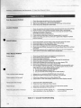
Problem
.~
...........
Suggested Action
Coin Mechanism Problem
1. Check the wiring connections to the coin mechanism.
2. Check the voltage to the + side of the mechanism.
3. Test the coin mechanism with the CorUtols Test screen in the self·test.
4. Check the power distribution board fuses.
Joystick Problem
1. Check the switches and potentiometers using the Controls Test in the self· lest.
2. Reset the limits on the joystick using the Controls Test in the self·lest.
3. Has the control been lubricated with the correct type of lubricant? If not.
lubricate il as shown in Figure 4-4.
4. Check the harnesses and connectors.
5. If you look the control aparl. have you reassembled it correctly?
6. Make sure all the parts of the conuol are in good order. Repair Of replace
e
parts as needed.
Sound Problem
1. Check the speaker volume setting: make sure the volume isn't zero!
2. Check both pariS 01 the Sound Board Tesl ln 'he selHest.
3. Check the voltage on the JXPWR connector.
4. Check the connections from the Quad Amp PCB to the speakers.
5. Check the audio ROMs' checksums in the Sound Board Test of the self-test
procedure.
6. Check the resistance of the speakers fOf 8 Ohms on the 4~ inch speakers
and 4 Ohms on the 8·inch woofer next 10 the coin box.
Video Display Problem
1. Check to see thai the game is plugged in and powered on.
Check the line fuse il no power is present.
Screen is dark
2.
3.
4.
5.
•
Check me display brighlness.
Check the solder connections on the line filler and the transformer.
Check the edge conneclor 10 the PCB.
6. Check the harnesses and connectors to the video display PCB.
7. Check ,he vol,age levels to me video display PCB.
8. Run through the following checklist. If you answer no to any question, you
have a problem with the video display. nat with the game circuitry. In this
case, refer to your video display service manual .
a. 00 you have power to the video display?
b. Ale the video display's filaments lit?
c. 00 you have the correct vollage to the video display?
Only a colored screen appeals
,
t. Attempt to run 8 complete RAMJROM test In the sell·test.
2. Replace the RAM if a RAM failure is reported In the self·test.
Picture wavers or is too small
t . Check me voltage levels to the video display PCB.
2. Check the 8+ to the video display. (ReIer to the video display manual.)
.'
Attract panel does nallight
1. Check the bulb In the attract panel.
2. Check the PO'wer Distribution Board fuses.
Picture Is wavy
1. Check the connection of the monitor ground wire to the monitor.
2. Check the connections 01 the sync in .
Picture is upside down or reversed
1. "you replaced the monitor res:enlly. cI'~
wire conneclions to Ihe video (jisplay. T'
Table 3- 1 General Troubleshooting
34
~
horizonlal or vertical yoke
y be swilched.
' --
~--~- . ~
. ~~~---c----~--~~------~--~---------------
,
Problem
Suggested Action
Convergence. pUrity or color problems
1. Use the self-lest mode to digitaJly adjuSllhe VIdeo display
2. Use the adjustment procedures in your video display manu!)1.
Picture is nOI centered
1. Use the centering procedures in your video display manual.
Table 3-1 General Troubleshooting, Continued
ROM./RAM.
'l1lc ROl\'ls and RAMs (.'o m::lin the progr:lmming routines
used by the g:UllC PCB set to control g3mc pby. Hef~r to
1able.}-2 RO.lfs rwd RlliHs 7i'Ollb/es/JOOtiIl8 to determine
the ROMs o r RA}.ils lhat are m~lrunctioning. Replace the
damaged ROt-.,t Or RAMs by rollowing the removal :lIld
inst:t1blion steps belo'....
I, nemove lhe game PCB SCI ~u:<."Ording to lhe pl'OC\..-durc
in the Primal Rase Game PCB 'el section.
CAUTION
Be/ore handling stalic-sensitive components. properly ground yourself to discharge
buildup 0/ stalic charges.
2. Remove the Cbm:lged ROl\ ls :1nd RAMs rrom the
PCB set using 3 dlip cxtr:tction tool.
g~uTlc
3. Insull the neW nOl\'ls ;l1ld IWls by plugging them in
the ga me PCB SCt sockets.
•
4. lte·inst.,U the ga me PCB ~t by fo il wing the steps in
the Primal R(lgc Gmlle PCB Sel S<.'Clion in the reverse
o rder.
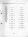
,
Problem
ROMs/RAMs Source and Purpose
Location
ROMs
The program wor'ks. but the motion
objects are incorrect Of non·existenl.
Motion Object ROMs and GALs (respons;ble for
mov,ng graphic objects)
15. 11 5-1SS. 9T.
17P. 22U. Also.
ROMs on rows V. W
Garbage appears on the screen or
game play doesn·t work correctly.
Program ROMs (responsible for game contra.)
24L-29L
The text or numbers are incprreci or
non·existent.
Alphanumeric ROM (responsible IOf controlling
graphic text and numbers)
22P/R
The sound is incorrect or non-existent.
Audio ROMs (responsible for controlling sound)
ROMs on Row 11 of
Sound CH31 board.
The moving backgrounds graphics afe
incorrect or non-existent.
Playfield ROMs (responsible lor controlling background
graph;cs)
25N-28N
RAMs
The display color is yellow.
Work;ng RAM
The display color is green.
VtdeoRAM
The display coIof is while.
CoforRAM
Table 3-2 ROMs and RAMs Troubleshooting
3-5
•
Voltage
Test Point or LED Location
Voltage Source and Purpose
+5" 025VDC
+5V low .:.: . High
Logic power from lhe sWlIchlng power supply.
-5 V
- VOP (p,' .. of LM324)
-5 V from the switching power supply (if connected).
-'--------"
Table 3-3 Voltage Inputs and Test Points
c. 13ricfly touch the bladc end of U1C screwdriver to
Video Display
To rcp:lir, replace o r make :ld l,·~ · mC nts to the video dispby, follow the removal and u ,~ ·.llIalioll steps below.
the CRT anode
by liding it under the 3node cap.
d. Wail 2 minutes and repeat the previolls -tcp.
3. Disconnect 311 ofthe wire h3rnesses from the video
displ3y.
WARNING
High Voltage
The video display conwJ's lelhal high vol/·
4. Unf:lsten the squ:lre-drive screws that secure the light
ages. To avoid injury. do r 'x service this display untit you observe a l orecautions necessary for workmg Ij '" high-voltage
5. Unfasten the square.<Jrive screws that 5eCUn.' the lower
Rl.3ss re[.1iner. Remove the dispby shield and Clrd·
ixYJrd bezels.
equipment.
6. UnfaSten the nat w:l.shcrs and nuts that sc ure the
video dispby Ch3SSis to the cabinet monitor mounting
br:lck.Is.
housing assembly 3nd remove it.
X·Radiat;on
This video display is deSigned 10 minimize
X·radiation. However, it; avoid possibfe
exposure 10 sol/ X·radla ly)(!. never modify
Ihe high· vol/age circUlI"/
7. Kemove the video display :Issembly from the ctbinel.
CA
I ON
Do nol al/empl 10 tW lOve Ihe video display
Implosion Hazard
The calhode·ray lube (CRT) may Implode if
slruck or dropped. The sf 8r.ered glass from
Ihe lube may cause InI'Jry up 10 six feel
away. Use care when h"'~ 'lng Ihe display
•
wilhoul ils chassis.
8. 1n.st.11J tJ1C new video display by following the previous
steps (excluding steps 23.- 2d.) in ule reverse order.
and when removing 111,,;,,'1"1 the game cabinet. Also, wear gloves to :;,roiecl your hands
(,om the sheet-metal eo';jt;s.
-----
I.
nfasten the 8 squ.3re UII \ c --crews that secure the
monitor door to the l"::lhinc' .. nd removc them.
1. Oisch:ugc lhe
(C IlT).
high ~voh :,g\,.'
ir'Jrn the
c lihode~r:IY
lube
NOTE
The label on Ihe video " 'splay assembly
shows a circuil for discha "; 19 the high·voII·
age conlained in Ihe CRT :0 ground when
Ihe power Is off.
a. 5e<.,\lrc onc cnd of a :-.- ,hI! I g3u!tt.· wire to a
insul3ted or wooden II.J:'.dlt.: screwdriver.
b. Secure the other end
ground.
3.(5
,~:
wcll~
thl! wire: (0 an eanh
9. If necessary. adjuSl the new video disp13Y's brightness.
size, centcring. purity and convergence according to
the video d~play service m:tnu:11.
CAUTION
The low·impedance (750) NeOlec NT·
2515C monilor (,,<ed in Ihe Alari Games
slandard Upf/ !
cab in e l) a nd high·
impedance Ham..
Polo 33" monilor (used
in the Showcase
tIbinet) are not inter·
changeable. If y
0 plan 10 replace an
existing monitor wltll he other type. you
must change resistors in the video driver cir·
cuils on Ihe Primal Rage game PCB. Refer
10 lhe game PCB schematic on page 5-6 for
more details.
CHAPTER
4
Part Ordering Informa.tlon
•
HIS CHAPTER provides information yo u
n eed to o rd er parts for your game . The
printed-circuit board (PCB) parts lists are arranged in alphabetical order by component. Within
each section the parts are arranged numerically by .
pan number. When you order parts, give the part
number, part name, the number of this manual, and
the serial number of your game. With this
information , we ca n fill your order
rapidly and cor rectl y. We h ope this
will create l es downtime and more
profit rrom your games. Atari Games
Customer ervicc phone numbers are
listed o n the in ide front cover o r this
manual.
e ll.......".:" . _ p .u n I LLWTIt"TIOI'IS
<¢o
PalJ,tAL RACi ! OP(IATOI'" "'AI'IUAL
,8"
Ie-Fla.
""",....
II2"WIdI.
-"".
........"
1 7 -I __~~::;;::
112" Wd l 1116°M ~
DtIf..SloId Foem Tapt
05340<1.(11
• ---
1-___1-_
a.,tl W/ Graphc:s
--~ 1--
0S30.16-0 I
. -,
""51'.0'
05 1679-01
17t372-OOl
.-
.,().2.
2·Aow ).OJ 2M
7 fr 1.,1N'III DIodI
15-61 128
II
30-1'
""-'"
t '~""""
\T!I014 . 1o..0
'IOAlIW""
1'2""
1 710~
'1C).:'<l2oncNull·
W.1IhIf AWl
--...
,'2,.."
17 1(109.001
.,otC .,PQfItICIn
" ,
•
----,-_
....
---....,
1600'4-<101
(If_
17823N)OI
178237.()02
(4 '**1
ytlow
Burson,..,.
_.~;~~ ~
1' -
Au,
OS3Ol9.(11
Fronl PaMI GriIIt
Items Nol Shown
176019·212
1410H-00J
SCI
Dr•
Screws (S _ _)
n»..
..."...."
-I _"""_
L-_ _ _
... .' ••••11
148015«11
" Orwft.8' Oia.
..........
1i*Nr"""
..
~,..,
"""'
176015-1 10
'10 • 50'8'. emu P'M'"d
Pa>Mid.. SIII·~
Saews (4 P'«*IJ
)I.ew.~~'-1
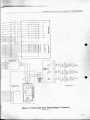
figure 4·1 Cabinet Overview
AOS}42O.Q1 A
4·2
-......."""••• :Y'"
.crtO &DIe
.
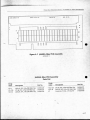
149016-002
· 5V O IA •• 12V 0 2A •• SV Al 2A
Swilching Power Supply
72·HA4806S
.8· 32 x 318Cross·Recessed Thrd·Forming Screw
053406-01
PowerSuppty
Chassis Base
•
@o
043908·01
PowerSuppty
Fuse Label
037640-01
Power Supply
Wamlng Label
146008.-3022
250V. Slow Blow
3 Amp Fuso
179225-2201
I·Pos. Fuse 8kx:k
72·HA4606S
16-32 x 3/8-
•
Thrd-Forming Screw
,
.'
Figure 4·2 ['ower Supply Assembly
o\OSjSI I.()1
4·3
• _ _ . ........ .. , ....... 1....• ... • • • • ~
C IlAPTllIl 4 _ PARTS I LLllSTurIO!"$
~
r ll"'AL RAGI O,tlATOI'S M MfUAL
NOTE: For best cisplay quality, use INs game PCB (from an AlaI1 Games standard upright cablnel)
ody with a Neolec: morilor. 00 not Instal this game PCB into a Showcase 33 Deluxe cabineL
Figure 4-5 Primal Rage Game (Gn PCB Assern " ly
4-8
.........
PklAlAI. RA !; O P[lATO"S :\1A~UAI.
~
CIIAPTl1a 4 - PARTS I LLU$TaATlO:oi5
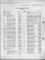
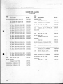
!'rlmal Rage Game PCB Assembly
Parts List
Deslg-
Oeslg.
nalo r
Desc:r lptlon
J'art No.
Ila(o r
In ll. 1n."1,
$F
5N
7B
7K
SOcket. 20
SockCl.. 16
Sockc...'t. 28
Soc:kL"I. 24
''V1pe
'\ lpe
8U
SK . 9N
9T
Sockel, 28 Pin . .300. Obi \vipe
Sockel, 20 I)in •.300. I)bl Wipe
SockCl.. 68 Pin, IJ(iA ror 68PLCC
inlegr.lIed Circuil
SodcCl.. 20 Pin . .300. Obi Wipe
Pin• .300. I)bl
Pin • .300. Obi
Pin•.300. Obi
I)in, .300. Obi
\'(ripe
Wipe
I'r. EPRO~I,
I'r. EPRO~I ,
PI, EPRO~I.
fIr. EPROM.
119302-028
1i9356-0328
119356-0320
119356-0316
Im56-0328
119356-0324
~
li93»0328
119356-0320
$ 1 2K.~ 100 ns, Mol> 0 1C39 136102-0301
$12K.'\8, 100 ns. Mol 0 2C1I 136102-0300
512KX8. 150 OS. PFOM Xx.u 1j6102-OO;1
512K."XB. 150 n.s, P~"() l Xxxx 136102-0050
Pr. EPRO~I. 5121(.'\8, 150 0$. Pfeil Xxxx 136102.()()$2
Pro EPRO~ I. SI2KXS. 100 ru, Pgm U
136102-004 1
Xxxx
I)r. EPRO~I, 512KX". 100 0$, Pgm Um
1 36102~3
x.~x:<
112M
I nu.~h.-d CarC'U11.
119237-068
lB
119356-0320
Ie
Imegf'Jled rcuil, 7 LSII
Inlegr.ltc...-d Clrroil. 7406
Inlegr.w.:d Circuil. 74LS24
hucgr.ued Circuit. 74FI57
13 1 9-001
1370$2-001
1370J8.()() 1
137494-001
lR
2A
Inlegr:ut."d Circuli. VRAM. 2561\.'\ . 100 os
inll'gr.Jled Circuil, 7"'1~'08
lntcgr:ued Cit'C\lil. 74F163
Rcs. R2RIO, 1 ' 2K.5WIO
137682·1 00
13748J.()()1
13734$-001
11801$-001
20
2C
2E
2K
iOlcgr:ued Circuil. 741 V
Intcgralcd Cireui!. 74HCT273
lnlt'gr.lIcd Circuit 74lS1S7
Integruu:..-'d Circuil. 7 FIS7
137062-001
1}76$$-001
137029.()O1
137494-001
2M
2R
2S
I01(.'gr:lloo Cimm. \'RAM. 256KX4. 100 OS
Imcgr:ned Circuit. 741-"08
Inlcgr:J.led Circuit. 14LS317
Inlcgrnu..-d Circuit. 74F378
137682· 100
137 BJ.()()1
137 14$-001
137612-001
2U
314M
3A
30
Intcgrnled Circuit. 7 FIG}
13734$-001
Intcgr:ued Ciraulo \'ml, 256KX4. 100 I\.~ 137682· 100
1180 1$.()() 1
Res. R2R IO. I ' ~ K, 511' 10
137062-00 1
lntcgr:ued Circuit. 741.527
Sockel. 28 Pin . .600. Obi Wipe
121l
12F. 12H Socket. 28 Pin . ..300. ObI Wipe
12K
SOtktl_ 24 Pin, _300. Obi "~pc
IZS, ijM,I3S SOckel. 20 Pm . .300, Obi Wipe
1793$6-0628
1i9356-0328
119356-0324
179356-0320
Socket. 24 Pin• .300. Dbl Wipe
SOtkel. 20 Pin• •300. Obi "~pc
SOckct, 28 Pin, .300. Obi \,<1p<:
Socket. 20 Pin . •300. Obi \Vipe
li9356-032
119356-0320
179356-0328
179356-0320
200, lORIS Sock<..'t. 68 Pin. PGA ror 68J1LCC
Integraled Circuit
21K, 21~VN Sockel. 28 Pin, .300. Dhl Wil)C
22,\
Socket. 20 Pin, .300. Obi Wipe
220
Socket. 28 Pin . .300. Obi Wipe
1 36 1 02~4
)(xxx
119302-028
119356-0320
~
14K
145, 1$5
16F, 16H_
171'. 175
Part No.
(Jr. EPROM. 512K.XB. 100 Ib, rgm Uu
m ,.IM
Sockel. Zip 28
1
Sockel. 20 Pin •. 300. Obi '~'ipc
211 .. U1. 31411, 314M, 3B, 3M, 4fl, 4M
Socket Zip 28
SockCl. 28 Pin, .300. Obi Wipe
$0
JG.\I.IIK,II
DcscriJulon
119237-068
1793»0328
119356-0320
1193»0328
IE
IK
1M
IN
2N
VWt, ZS6KX4, 100 ItS 137682-100
22E
SOcket. 20 Pin, ..300. Obi Wipe
22H
Socket. 24 Pin . .600 Obi \'Vil>c
22UO, 23E.
Sockcl. 20 Pin, .300. Obi \1;'1 1)(:
24E
24 H
Sock<..1. 32 Pin •. 600. gbl \'('lpe
119356-0320
1193$6-0624
25£
26H
2IT,27U
28H,29H
119356-0324
1193$6-0632
1193$6.()640
Ii93$6-0632
3C
3~ 1
Imegrnted Circuit. 741 1CT273
1376$$-001
137029-001
Imc!(r.:lted Circuit 741.5157
Imcgr.lIc...'ti Cin.:uil . 7 FI;
137·194-00 I
Iml.'grJled Circuli. VRAM. 2S6KX , 100 n:. 1j7~2· I OO
179369-0096
1190$1-001
3N
3R
Il1Ic:gr.noo Cireui!. 7
Socket, 24 Pin, .300. Obi
Socket. 32 Pin . .600. Dbl
Socket. 40 Pin, .600. Obi
Sockel. 32 Pin • •600. Obi
Wipe
\,('ipe
Wipe
\~'ipc
119356-0320
1193$6-0632
3£
3K
IJr. I020-6tWLCC FPJ.f.I, 20D x.'t.'Ot
Pro EPROM, I28KXR, 100 lb. AII>h:l
1)6101-100)
3U
Inlcgr.llt.-d Cimlll. 7 1~ 1 57
Intc...-grnlt..'tI Ci lIll. F3"S
I3748}-OO I
137622-001
13749' -001
137612-001
)(xxx •
r36102~$
A
411
Res. It2RIO. IK/2K. :-'11'10
Imc1!l".lIed Circuit. 74LSZ
I ISO I;..O() 1
13i062.()()1
Shroud. 96Ch.'T OlN41621
JXD
++IOOSV I Tc:5l Poim
3S
Pro E"RO~1. SI2KX • 100 0:.. Pgm Lm
1)6102-00' 2
XxX)(
Imcgrnled Cirtllll, 74F08
1~3n
1·9
•
•
.....
C II"rTU 4 _ P.\ltn I U UST ltATl OS S
<>
l'IlIU"L RAGr: O,t:UTOIl'
M"l'iUAl
T-MEK Game PCB Assembly. Continued
Parts List
O<.-slg'
lI:nor
4C
4E
K
'iM
4N
4R
•
4S
41)
;0
IE
,)
5K,5M
R
- ,5U
1>c,.'Scrlplio n
P'MI No,
Intcgtnted Cirttut, 74 110773
Imcgr.II\."tI Circtllt, 74LS I 57
137655-001
137029-001
Imclolr:iled CirCUlI. 7:iFIS7
InIt'8I"'JIt'd Urcull. VHA~I , 256KX4. 100 ns
Integr.lIc."tI Circuli , 74FJ2
IntC!'gr:m.-d Cm:uil. 741;,3
137494·001
rcull.741'15
I llt~r:uoo
Inlegt:ued Cirout. 4FI6;\
Ime-gr:l.loo CircuLI. 741.,:,245
InlegrJted CircuLI . 70iLSIS
137491-001
13734 5-00 I
137134-00 I
137029-001
roe
lntc.'Sr:ltc..-d Circuli. 7
ImegI"'JIc.."Cl CircUIt. 74 FtS7
Intc.1VJled Irrull. 741.S2 .j
I nlc~r.tlc..-d Cimut. 74 F 169
137682·100
137486-001
13 145-001
1374 3-001
137494-001
137038-001
137 96-001
Deslg·
nator
Description
Part No .
100
10E
10F, 10)
10K
Inu:groll."tI CiR..'uil. 74F37
Intcgr:l.Ioo Circuit 74LS I 57
IlIIcgr,uc,'d Circuil. 74Ft 53
ImegI"'Jlc.'Ci Circuit, 74LS86
137420-001
137029·001
137492-001
137079-001
ION
lOR
li D, li E
Integrnlc..-d Circuit, 4lS163 A
Intt'grat('CI Circuit. 74F04
Im(.'gr-.lIoo Circuit. 4m3
Intcgr:m.-d Circuit. 74F04
13711 4-001
137437-001
1}7610-001
137437.()()1
137345-001
137420-001
1211
Inlegr'3led Circuli, 7 F1 63
Integrated Circuit, 74F374
ImcgrJt(.'CI Circuit, SRAM. 32 1\.:\8.
25 os, .3
12M
CrysI.I. 28.636 Mill, Osc. Module
13767G-025
144008-009
liN
II U
120, 12E
12N
5V!II5VLO LED. Red. T1- 314.
8O-Ileg
Integrated Cirt'Uil.
60
lntcgr.lltd elmlil.
6"
6F, 6K. 6.\1 Inlegrnled Clm)!!.
13802 1-00 1
137420-001
137029001
137494-001
6U
Inlc.-gl"'Jled CircUlI.
Imcgr-Jted Circuit.
Intl'gr:ned CII'cuit,
Inlegr.lIed Circuit.
74F32
74t.S2 '"
74f260
74F3n
137486-001
137038-001
137570-001
137622-001
0
-E
F. 7)
7"
hllc..'8rJ1c.-d CircuIt.
Imegr.ued Circuil,
ImegrJled Circuit
Ime-grone<! Circuit,
74LS245
"'LSIS?
74Fl53
74LS74
137 134.()() I
137029-001
137 92-001
137023-001
6S
N
R
7U
80
8E
8F,8)
8.\1
~
HR
90
9E
9F,9)
9K
9~1
9R
4- 10
Illlcgr:ued Circuit.
Inlegr:lled Circuil.
12U
imcgl'3loo Circuil.
1:1/1 E. 13D Integrntt.'<.! Circuil,
121'
74F374
74LS I 'j7
74F157
6N
6R
•
Diffused, .;MCO.
13K
13N
137486-001
137483-001
137622-001
137496-001
InlcJY3It.'t! Circuil, 7 1-'374
In1eStr3l00 CIrcuil. 7ofts t)?
Imegr:ued Circuit 74F 153
hllcgr:ued Ci~uit . 7 n7
137420-001
137029-001
137492-001
1;\7531-001
Intc..'Kf'JI<."<l Cil'CUil. 7~FU8
Inlcgr:lh..'tl Cil'C\lil. 7 F02
int('grnted CirculI. 7 I 245
!mc..'),(r:llt.'tl Orruit. 74L.S 15
137483-001
1.l7481-OO1
137134-001
137029-001
Intq;r:J.Ic."I..! CirnUI. ]. IF I S3
Intct;r;i't(."1..! CirCUli,
In1t'8r.1I00 Cimul. ':'qF1 63
InlcgI"JIc.."I..! Cirtuit. 7'1f-"00
1;\7492-001
(17;70-001
13734 5.()() I
1.17327-001
-
,,"260
137486-001
137436-001
137420-001
13734 5.()() I
13U
14/15E
14A. 140
140
14M
Inlegl"2led Circuit, 74F273
imegl"'.ued Circuit, 741.5257
lntegr..ued Circuit, 74F273
Imegr.ued Circuil. 74FOO
137610-00 1
137 136-001
137610-001
137327-001
14N
14U
15A, 150
inlcgr:ned
Intcgl'2led
Inlegr:ued
tnle-groued
137494-001
137420-001
137345-001
137 136-001
150
15K
15M
15N
Integr:ued Circuit. 74F374
int(.'grate<l Circuil, 74Ft;}
Intcgl':U<..--'d Circuit, 74FS6
Integr.Ued Circuit. 7 Ft53
137420-001
137492·001
137649001
137492·001
I; P
15U
16A, 16B
160
tntcgrJl(.-d CirnLil. 74 F374
Integr:ucd CirctJil, 74F l63
Intcgr:lIoo Circuit, 741.S2;7
Inlcgnlled Circuit. 74l.S24;
137420-001
137345-001
137 136-001
137 134-001
16&
1611.
I.ulekr.ucd Circuil. 74F374
InlcgrJtc."<l Circuit, RAM. 32KX8.
13 420-001
25 ns . .3
16K
Inlcgr:llcd Circuit. 741.S04
Inlegrated Circuit. 74F!53
13767G-025
I37()()1).()()1
137492·001
13P
16.\1. 16N
Circuil. 74F32
Circuil. 74F74
Circuit. 74F374
Circuil, 74Ft63
137436-001
137610-001
137345'()()1
137 134·001
InlcgrJted
integr:lIed
Imegr:uc<l
Integr:lIed
141'
llllcgr:ued Circuil. 7 F32
Integr:ued Circuli. 7 F08
Integr:lIed CirC\w!> 74F3n
Intcgr:ucd Circuit: " 1:--169
74f74
74F273
74 Ft63
7415245
Circuit, 74FI )?
Circuit, 74F374
Circuit. 7.fF 163
Circuit. 74LS257
.~ .~ -
Primal Rage Game I'CB Assembly. Continued
Parts LIst
Des IS·
nator
No.
1374!»OOI
137420-001
137502-001
13 040-001
17M, 17N
Imcgmlcd Circuit, 741S 148
Inll.,&r:ltoo Circuil. 74LS245
Inlcgr:Ht..'d Circuit. 74LS I>7
Imcgr.ue<i Circuit. 74FIS,}
137 17-001
137134-001
137029-001
137 92-001
I U
18U. 181l
I E
ISF
Intcgr:uL"(1 Cirodl. 74 ...244
Integr.atcd Circuit, 7 LS245
Integr.ued Circuil. 74F04
Imcgr:noo Circuit, 74LS74
1.\7502-001
137134-001
13 437-001
137023-001
1811
I K. IBM
18N
18U
Imev-ned Circuil, 74F I38
irllcgr:ued Circuit. 74F153
Inlcgf3ted Circuit, 741.S1G3 A
Imcgl':necl Circuit. 74F I63
137521-001
137492-001
137114-001
I3734S-001
19A
1911
19E
19F
Inlegnued CirCUil. OS1232
Integmled Circuil. 741.5273
Intcgr.noo Circuli, 74LS 4
Integr:uoo Circuil, 74F I38
13n62-OO1
n7040-001
137023-001
137S21-OO1
19K. 19M
191'1
19U
20E
Inl(.-'8rJ l~
Ciraul.
Int<:graloo Circuil.
Integr:ul.."<.1 Circuil,
Ill1cgmted Circuli,
7·iLS2·15
74LS 163 A
741:163
74F08
137134-001
13711 -001
13734S-001
1374 3-001
20f
201'
IntegI':H'-.'tI Circuli. 74FI38
Intcgl':Hed Circuil, 7 37
Intcgr:tted Circuit. 74LS 163 A
Integrnted Circuit, 741$378
13 521-001
13 144-001
137114-001
13730S-001
lORIS
lOU
21n25
21B
Inh:gr:lIcd Circuil, CPU, I'LCC
Inlegr.uoo Clrcull,·14F l63
Imcgt2too Circuil. 41'04
Inh.·gr.ll<.-'d Cirruil, 741S245
1376S8-101
13734S-001
137437-001
137134-001
21K,21~VN
21P
21U
228
Imegr.uoo Circuil. SRM1. 32
25 11:" .3
Integrated Circuil, 74LS3n
Intcgt::l1oo Circuit, 74 F163
Imcgr.l1e<1 Cireui!, 141 2 5
13767002S
13 145-001
13734S-OOI
13 134·001
221)
22 11
22K,22M
21 1
Inll'gt::lIed Circuit, SRAM, 8KXB, 2; 115, 3137667'()25
11l1<.'8t:ltcd Cin:tlil , 2KC 16-200. 200 ns 137648-200
Intcgt::ul'<l Circuit. 741.5245
137134·001
Ij730S-001
In1cgr:uc..'<1 elK'uil. '115378
225
2ZU.23/2
Inl("8I':III.."<.I Circuit, 7-tFo'(
IntcHr:1It.'d Circuit. 741.5273
171l
17E
17K
Inlcgr:ul.'tl Circuit,
Inlcgr:ued Circuit,
Imegr.ued eimlit,
Inlcgr:ned Circuit.
~rt
74FtSt
74F374
741-"244
74LSZ7'}
161'
165
16U
17A
.-
Description
Ocslg.
nator
Description
Part No.
13A
13B
Intcgr:1U.."d Circuit. 74LS244
Inl("gr.ttoo Circuit, 74LS273
137038-001
137040-001
130
2311
23K.23M
13N
11l1("gr:ucd Circuit.
Int('gr:ned Circuit,
Intcgr:1tt.'<.I Circuit,
Illlegr:noo Circuit.
741.5245
74F32
741$374
74LS378
137134-001
137486-001
137144-001
13730S-001
13P
13R
24A
24n.2 0
IntcgrntL'd Circuil. 7oiLSIS7
Integrated Circuit, 14LSj77
Inlt:gr:ul.'(( Circuil. 74LS245
100egr.ltl.-d Circuit. 74 1~245
137029·001
13714S-OOI
137134-001
137S91·001
241 1
25A
2SB
Intt:gnued Cit'C\JiI, SRAM, 32KX8. 70 05. .GI37615'()70
Integl':ued Circuil. 74LS24S
137134-001
Imeg.rnled Circuit. 74F24S
137591-001
Int('JlrJtoo Circuit. SRAM, 32KX8,
70 n5 • •6
13761S-070
2611
VB
27T
Integnned Circu il, 74FIG3
Imegr.ucd Circuit, 50S
Z7U
28B
C~ttll.
280
-
2OK, 20.\1
201'1
137 37-001
137040-001
28E
28H
29B
29H
Integr.ued Circuit, POlS
50.000 MHz., OSC. !\'1odule
I3714S·001
137SSO-001
137419·101
I44008-00S
Inlegr:lIed Circuil, CPU, 68EC020.
2S MHz, 100PQFP
13769I-02S
Inlegr:lted Circuit, I ~, 16 13
13n46-001
Int<gr.lled Ci.cu;I, SWI. 32KXB. 70 ns, .613761>0 0
Integrated Circuit. 74F20
1.\7S30-001
Imegl':ucd Circuil, RAM,321O(8,
;0 ns . .6
29S
Imegrated Circuit. 7 LS298
Imegntled Circuil. 74LSI53
Imev.lled Circuil, 741.5298
13761S-070
137201-001
137104-001
137201-001
A
Pro Fpla, 20N • 9T 44GD
13609-1-0004
A
A
Pro GA1I6V8. 25KS,
Pro GA1I6V8. IONS.
Pro GAL I6V8. ISNS.
Pr, GA1I6\'8. ISNS.
136101-0011
136101 ·1220
136101-0021
136101 -0013
29N
291'
A
A
A
A
A
Pro GA1I6V8.
Pr, GAI.1 6V8.
I'r. GA1I6V8.
I'r, GALl6V8.
A
A
A
A
I'r,
I'r,
I'r.
I'r.
A
•
11K nEil
2ZUll 3863
22A 2A8 A
23e 7;<;3
2SNS, 125 4A81
2SN , 9N SAf.O
2SN . 17S 3139
2SNS, 13~1 5C'>i
GALI 6VS. 25NS.
GAU6VS. 25NS.
GALlGV8. 25NS.
GALI6V8. ION,
171' 270 II
liS 251='2
2>11:: 477 A
IS 1153S
13609-1-00 14
136101·0012
13609-1·0007
136101· 1008
I.\<
rxl l5
I360<!-,-OO 16
136101-00 18
136101·0006
4· 11
•
. ...... .....
. .....
e ll.o n. 4 _ P.UTS h ,l,USTUTl O1'(5 '> PJUJ,iAl RAGE O'fkAToa'S MANUAL
Primal Rage Game PCB Assembly. Continued
Parts List
Oeslgn::U or
OeslgDescriplio n
Part No.
"r, GAL I6V8. 2 NS, I O~1 326F
I' r, GAl.2OVS, 2.5 ,71< 9CA6
I'r. GAL22VIO. IO:-J , 25E D358
Pr. GAL22VIO, 15N • 12K 75.53
136 I0 J.()009
136101-0019
136101-0017
136101-IOZZ
A
PI', I)ROM, 825147. 135 7 136
"r, PROM. 82514;. 145 FOS5
Pro PR M,8 147. ISS 91361
136094-000 I
136094-OOOZ
136094-0003
ADCI
Connc.."('(Qr. 2 Circuil. HC3der. .1 00 Clr 179()48.()O2
AU'HA
SntkCl, 32 Pm,
ANLO
Rcs~or.
A
A
A
A
u a(or
e
II
U
.600. Obi· ... Ipc
10 n. :t~. I
\\'1
I',. ALI6\'8. 25N , Z2E Il8ZE
"I'. GALI6V8. 25NS. 8K 5ADE
C;.cs
<:9-C12
CI.3-CI;
•
elG
CI
CIS
CI9
JMPWR
Conneaor. 9 Ckt, Header•. 156 O r. RI,
Key 3
17916>-009
Conncccor, IS Ot. He-.Ider. .1 00 Clr
1791 18-015
Connector, 96 QI. Rcpt. p"""fil. Long 17936G-0096
136101-102;
136101-0010
JRES
JSY 'CI
JWOIS
('7MA. C7M
Ctp.lcilor, "7 pF, 100 v. :t~ cel'3mic 122016470
'11):lcilor. 1000 pF. 100 v. :110%. Ccr. 12201;'102
Otpadtor. 270PFC. 50 V. EMI Filler
140006-271
C:lp:lCltOr. 100 pF. 100 v, t59l. Q.."r.unic 1220 16-101
CapadiOf• . IIJF.;o v. :l~2(M. Cer. 122002·1()4
C:>p:idlor. .01 "F.;o V.•~-. Cor. 122002-103
C:>p,dl"" .1 "F.;o V.•~-. Cor. 122002· 104
JXBUS
jXJ'WR
C:lp3dlor• •01 lIF, SO V. t.8(M-2CJI9l. Cer. I22002- 103
Cap:t.cilor. . 1 lIF. SO v. :t8Ot&-2<M. Cer. 122002-1 04
C.1pacilor. •0 1 }IF, 50 v. t8Ot&-2(M, Cer. 122002~ 103
Cap:lcilor. •1 pF,;o v. -;~2096. Cer. 122002-104
C38-C I
0I2·C;o
C;I. C;2
C:11)3010r, .Oll/F. 50 V. :t~2(M. Cet.
Qlp:lolor, . I IJP.;o v. i809tt-2096. Cer.
C:>p.1dIO' . .01I'F.;o v.•
Cor.
alp-leilor•. l lIF.;o v. :t8O%-20t6.. CCr.
C,3-C60
8096--.
122002- 103
122002- 104
122002-103
122002-104
C61. C62 C.1P.l itOf', .0 1 J.lF, 50 v. ±~2(M, Cer. 122002- 103
C6j-017. C319. 021 , 023, 026. 028. C33O. 032
c'1)l:lt:llor•. 1 ~IF. SO v, :t1:Im6-~ Ccr. 122002-104
C3p:K:IIl:>r. 7 pF, 100 v.
CRI. CK2
4-12
1);00.,. IN 001
t.~
Ce:rnmic 112016-410
IjlO48-OO1
Shroud. 96C~'T, OlN4 1621
Conncaor. 2 Circuit. BeatieI'. . 100 Clr
Connector. 3 Ckt. l'leader, .100 Clr
Conneaor. 2 Circuit. He3der• . 100 Or
Connector.
96 Ckl. Rcpt.
~ressfll , Long
179369-0096
179048-002
179018-003
179048-002
179368-0096
COnnector. 9 Oct, He;ldcr•. 156 Clr, RI,
Key 3
17916;-009
M2GM, M4GM. M I ~8M. M248M
Resistor. 10 a. ±S~ l/8 W
MOli_O-MOI'U M O L_O-MO L_~ PFOII. PFOt,
PFI I
Sockel. 32 Pin . .600. Obi Wipe
110027-100
P~'OM , PFI H, PF It,
1793j6.()632
PG~UL
Socket; 32 Pin •.600. DbI U'ipc
PG~U.M
Socket. 32 Pin •.600. Dbl \'Vipe
Socket. 32 Pin • .600. Obi \'C'ipe
Socket. 32 Pin • •600. Obi Wipe
1793j6.()632
1793j6.()632
1793j6.()632
1793j6.()632
Tt'3ll5istor, 2N3904
Transistor, 2;''0/5306
133041-001
133033-001
PGM_UM
PGM_UU
QI-Q3
Q4.Q;
C20.01
02. C23
04-01
C32-<:3
1790> 1-00 1
Conm."('(or, 2 Citnlit. fieader, .100 ar 179048-002
JRBUS)
C:lp:! IIor. .01 I,F.;o . +~-. Cer_ 122002- 103
C7M1-C7M~ .
Test Point
Connect"', 6 On, HC2dc'• .1>6 Q" Key 3 1792 13-006
110027-100
C.lpacitor, 100 pF, 100 V, t.5'Jl, cernmic l2-'>01 6-101
p.'l itor. 100 "F, 16 v, Electrolytic,
Axl:ll
124008-107
C
C:lp.u.:ilor. ,I pP, ~ v. ...~20%. Ccr. 122002· 104
C~M 1-01'1;.
C ~W
Cap.1dtor, 47 pF, 100 .:5%, Ccr:unic 122016-470
110027-100
J3
JpLI
JRB
CI.O
Resistor, 10 a. ±5%' 1/8 W
JAUD
1793j6.()632
o
Part No.
EOSC. EC2;X.F-E2K
GNOI-7
A
A
Oc=scriptlon
PF6B. pFS6B. pFR4M
Resistor. 10
Rl
R2
R3
1t4
a. t59l. 118 W
Resistor, 470 a. t.5,., 1/8 W
Itcsi5tor, 75 a. :t596. 1/8 w
nesislor. 470 a. : 5%. 1/8 W
Resisto r. 10 a, ±S96, 1/8 \V
110027-100
110027-471
110027-7;0
110027-47 1
110027- 100
K4MI -R4M,. R4MP
R5
1t6
R7
Resistor, 47 n. ±S' I \'(I
Resistor. 100 n. ±596. 1/8 W
Resistor. I K n. :t59'. 1/8 \V
Resistor. 2,4 K
n. 1 5'6. I
47 n, ±~ I
\V
R7MA
Roi~or.
R8
Resistor. 7 a , :t"" 1/8 \V
W
IIOOZ7-470
110027-101
110027- 102
110027-242
110027- 70
110027-7;0
Primal Rage Game PCB Assembly. Continued
Parts List
Designator
Description
"art No.
nator
R9
RI O
Resistor. 10 0 , t)~. 1/lJ W
Resi~or. 100 n. t5%. 1 \VI
110027-1 00
110027- 101
RII
Resiscor, I K n , .t5%. J \'(,
Re.si51:or. 2.4 K n. 15%. l/8 \'it
110027- 102
110027-242
110027-750
11 0027- 100
RI 53
ROlStOr. 2.2 K n. is''- 118 \'(1
IlI 54
R~blor. 10 K O. 15%. 118 W
RI 56-RI 58 Rc~.i...tor, 100
15%, 1/8 \VI
RC5istor, I K n. 1-.5%, 118 w
IlI59
110027-222
110027-1 03
11 0027-1 01
11 0027- 102
Resistor. 10 n. .tS%. 1/8 W
R16 1. RI62 ResiStor. I K n. t)%. 1./ 8 W
RI G3. RI64 Rcs~or, 10 n. .15%. 1/8 W
RI67
Ro~or, 510 n, 15... I W
11 0027· 100
110027· 102
110027- 100
110027·510
RI2
RI 3
RI4
Des ig·
RC$lsI:or. 75
n, .:tS96..
1/8 \Y!
Resislor. 10 n, 1~. I
\r,1
RI 5
Rt.'Sislor. 100 n, :tS%. lIS W
RI 6
Resistor, I K
RI7
RI8
n. i59\.
1/8 W
Resistor, 2.4 K n, 159'. 1/8 \"II
Resislor. 0 n. t51t6.. 114 \\"
n. is''" I
11 0027- 101
11 0027- 102
110027-242
110005-001
R1 9. R20
R20D
Rli
R22·R25
Rbi:Mor,
Resistor, 470
R26. R27
R28-RJ5
1\36-R45
Resistor. 1 K
R46
Rcsbto r. I K
1./8 W
1./ 8 W
11 0027471
11 0027·102
11 002747 1
11 0027·102
R47
Resblor, 470 n, iS9\. 1./8 W
Resistor, I K n. is%. 1./8 W
Resistor, 470
1596. 118 W
Rcsislor. I K
'596. 1/8 W
110027471
110027· 102
110027471
110027·102
Rcsl5lor. "70 n . ±5'l 118 W
110027471
11 0027-1 03
110027- 102
110027472
R48. R49
R50-R57
R58-R68
R69
Rc:sislor. I K
W
to n. t ~ )/8 W
n. t"*'. 1/8 W
Resislor.
J
K n, t5" . 1/8 W
ResiStor, 470 0 , is''. 1/8 \'(1
n. tS%. 118 W
Reslslo r. 470
n. is%,
n. is%.
n.
n.
n.
Ri().Rn
R78-R83
R84
Resistor. 10 K
t)9l 1/8 w
Rc;.'Slstor, 1 K 0 , is%. 118 W
R"""or. 4.7 K
1/8 \V
R85-R97
R98-R I09
RII o-RI23
RI24
Resi5cor. I K 0 , :t59' LJ8 \V
R1_5
Resblor, 220 a, 1596. 1/8 W
n.'''''
Resistor. 470 n. 1596. 1/8 w
.is,,
Resistor, 10 n.
liS W
ResislOl". 100 0 , :t.~. 118 \V
11 0027·221
110027-1 0 1
11 0027- 103
11 0027-100
ResiStor. I K n, i ~. LI8 \VI
Resistor• .f70 n. 159'<. 118 \l'
Resistor. 4. K n. :15%. 118 W
Resistor. 10 K
I W
11 0027-102
11 0027-..17 1
11 0027472
11 0027- 103
RI28
ResislOr.
RI 29. RI 30 Resistor.
RI34
RI36
11 0027-102
11 002747 1
11 0027-100
11 0027· 101
n. 1-5'f,. V8 \V
10 K n. :tS%.. 116 W
10 n. :t5%. 118 W
R126. RI27 Resistor, 100
RI 31
RI 33
llooZ7-I02
llooZ7-loo
11 0027-4 1
110027- 102
n. is%.
n. 1~. 1/8 \VI
n. 1 ~ liS W
RI37, RI 38 R islur. 220
R1 39-R146 Rt$i.slor. 10
RI·i'1. RI48 Resl.)tOJ', 7 n. .:59'. 118 W
R149. RI52 Res~or. I K n. .t~. 118 W
11 0027-221
11 0027- 100
n 0027470
11 002 -1 02
Ocsc.ripl,iOIl
Part No.
n.
RI 60
"'or. 10 n, . "., 1/8 W
Re5I.."tor. 11 .0 K n. 11'" 114 W
R"",o<. 10., K n,
1/4 W
110027·1 00
11 0027·103
ll ooYl -1I 02
110034-10;2
Rcsbtor. I K n. ±;%., 11'8 w
Rc>islor. 39 K
'5" 1/8 W
RI 7oi, RI 7S RCSlSCor. 39.2 K 11'" 1/4 W
R176
Res~or. 470 n. :1)%, 1/8 W
110027- 102
110027-393
110034-3922
110027-47 1
R178
Resistor. 47 n. .tS,.. 1/8 W
R1 79. RI 80 R ~istor. 10 K
:16%. 118 \XI
RIS I
Resistor. 7 K
t 596. I W
RI84
ResIStor. 10 K :596. 1/8 w
11 0027 70
11 0027-103
11 0027·472
11 0027-103
KI68
RI 69
RI 70
RI 71
R
R"",,,><. 10 Kn. •,'" 1/8 \V
tI"
H172
n.
n.
K 173
n.
n.
n.
RI 86
HISS
RI 89
RI 90
n.
R('Si~or. I K
i596. 1/8 W
Resistor. 10 n. .t.59l 118 W
Resistor. 470 n. t 59l 118 w
Re~lstor. 10 K
15'6. )/8 W
n.
110027· 102
110027-100
11002 471
110027- 103
R191. RI92 R~isu:)I'. I K n, 15" 1/8 W
R194
Rcsislo.-. 470 n.•"., 118 W
RI96
Rcsblor. I K n, i5". 1/8 \'(1
R202
Resislor. 4i O. :t:59', 1/8 W
110027- 102
110027 I
110027-102
11 0027470
R204
Reo-islor, 4.7 K n. is,., 1/8 W
R205
Res.islor, 47
:1:5,.. 1/8 W
R207, R208. RlIO. RlII . R214. R217. R218
Re:.lSlOf. 10 K O . !S"'. 1/8 W
11002 -472
110027470
n.
RM()().RM07
Rc:.i.o.ror. 47 n, :l~ 1/8 \V
RVGND
Rcsi.t;;lor. 0 O. :t ~ I10i w
Switch. Slide, SPOT
VCRI
WDOK
XI 2
11 0027-103
110027- 0
110005-001
160040-001
Connl'C1Of, 2 Circuil. HCJd<:r•. 100 Ctr 1790-18-002
LEO. Itl"tJ. TI ·314. OLffu.sc..-d • .5MCI).
so- Dcg
Resc.lor. 10
138021-00 I
n. t.~ 1/8 \V
•
11 0027· t OO
4 - /3
•
..
'
._.....__.- . ....
C II"rTU " - ".40115 ILLUSTRATION$
*
PllMAl RAG ! OPt: ....TO.·S MANUAL
NOT E S
•
•
..
4- 14
......
~
....
VI IN ... L RAo! OPraATO.·S M"',..UAL
-. -, o
,.
p
.
-
i
u
0
..... 0
.
,
i
u.
,1
C ..... 'TU 4 - PA.a n I LLUSTR ...TIONS
...
0 ·'
I
oQo
i
CI'
0
... ,
0
""1
•
!
1
.;
.. 0
aO
,
-
,
;
i
i
mO
000
o
"I
(I '
-.
-,
t
,
•
I
i
,.
0
....
.
i
Q
0
""
ell
O
U.
"'f
0
I +1
- -,
_. _.
j
,
-
'"
,
-
i
P'
.....
0
PI
.....,
0
U't
"".
0
I +1
-
-,
.
-
..... 0
CI.
~::r--Fi-
Qt,
0
•.
•
•
... ,
.1!
ii~;
o
L -____________________________________
0-
o
~
~ --------------------~
U
Figure 4-6 GT24M8 rCB Assembly
A01)601.02 It.
4-15
GT24M8 PCB Assembly
Parts List
•
O c..'S lg.
nato r
Dc..- scriptlo n
(~ISI · 1I
3) Screw, Pan, 440.'
Pa.rt No.
, X·Ree, Cad
172025-3206
A
A
I'f, GAL16V8. I O~-s. Ronxl« 501-"8
')r, GA1l6VS. 151'\5. Unkdec 11-"00
1)6102-0260
1)6102-0261
A
A
A
A
Ilr. Mrom,
I~. Mrom.
IJr, Mrom.
I',. "'rom,
A
Pr. Mrorll, 1M: . 100;'; ', MOil 1.1 401:."9
I'r, Mrorn, IMX8. l OON ', MOHO.7 F,38
A
A
A
A
A
A
A
IMX8. I OO~tS. 10101.0.2 SFCS
IMXS. 1 00~ " 10101.0.6 96C1
IMX8. 1001'.5. MOLOA 90UD
IMX8. 1 00~S. MOLl.O 9FB6
1)610H)320
1)6102-0328
1)6102-0324
1)6102-0332
018M. &18-'1. BI48M
R",. 10 0 .
BNKDEC
Sockel. 20 Pin• .300. Dl>I Wipe
179356-0320
USl , OS2
Res. 10 0 , t ~ lIB W
110027·100
Cl.eIA,C ID Cap:1cilor. 100 ~F. 16 V. Electrol}'tic. Axial 124()(8. I07
Up:aOIOl"• .I pF. ;0 V, +8C*-2<M. CA"f. 122002· 104
Cl-C.I7
GNDI-GND,
TCSI Poim
I790S I'()o1
)!li11l2 'HI7
A
Pr, ~hom, IMX8, lOONS, MOI.O.3 D4DF 136102-0322
Pr,Mrom. IMX8. lOONS, MOHI.3 6AFB 1)6102-0339
f
0245
1 J6 lOl~jll
A
Pr, t.lrom, 1M. • 100, -. MOH 1.1 ESOC 1)6102-033,
Pr. Mrom, IMX8, lOON . MOLI.I BA48 1)6102-0334
Pr. Mrom, I~LX8. lOONS. MOIH .O 106 A 1)6102-0333
Pr, Mrom. IMX8. lOONS. MOHOA FJEE 1)6102-032,
1.24,
Res, 10 n .:~ J, 8 \,(,.
4· 16
Conn«tor. 2 0.1. 1I(.':ldcr, .100 Or
.,
1}7;91-OO1
•
110027·103
110027·100
110027·103
11 0027· 100
1790-18-002
MOl IO.o.MOI10.7. MUI II.o-MUIII .j, t-.iOW.o-MOW.7. MULJ .O-MOLI.3
Socket. 32 Pin, 600. Obi Wipe
1793>6-0632
Resistor. 33 n. •~ lIB W
RI ·R40
R41
ResiSlOf. 4.7 n K.~. 12M., 118 \V
110027· 330
1180 I().4n
RO~IDEC
Socket 20 Pin• .300. Obi Wipe
179356-0320
RSZ\· RS23 Res, 10 0 ,
t,,,
R1ltM().RlltM7
Res, 47 !l.
•
110027·100
ABO-AD2. AOI().ABI2
Integr:ued Circuil. ':'·11-"24)
OIM, IJ<IM Res. 10K n, :t ~ 1/8 \'Q
Res, 10 n. ±~ I 8 \'(,
08101
UIIM,Ul 4M Res. 10K O. :t;"- I tI W
Res, 10 n • .t~ 118 W
122016-470
179048-002
jBSO. jllS3 Connector, 2 Ou, HC3der, .1 00 Or
Connmor. 9 Ou, HC3dcr• .156. Key 3. HI 179213-109
JPWRI
JRS7.o
•
11 0027· 100
137591-001
I't, MI\ "Il, IMXH, 1I I IN'i, MOIIOO ()A ll \
IIr, t.hulII. IMXij, IOU S, MUIIU..!! U.li\(,
A
W
DUO. OBI . DBIO. OBII
Inlcgr:lIed Cirruil. 74F245
A
A
A
A
I
1)6102-0330
I", Mrom, IMX8. lOONS. MOHO.S 9060 1)6102-o}27
Pr, Mrom, IMX8, lOON, 10101.0.1 CF92 1)6102-0318
I'r, Mrom, lM.•'(8, lOONS. MOHO.' D5E7 1)6102-0323
PT, Ml'Om, IMX8, 100:-:5, MOLO.7 8285
A
A
t~
CTRM(KTRM7
Cap:10Ior. 47 pF. 100 V, :t~ Cer.
1)6102-03)6
1)6102-0329
1}6102-O338
1)6102-0326
A
Part No.
Descr iptio n
1)6102-033
1)6102-0331
Pr. Mrom, IMX8. lOONS. MOI·IO. I 891"0 1)6102-0319
Pr, ~Irom. IMX8. lOON. MOLO.O 069E 1)6102-0316
I'r. Mrom, It.LXB, lOONS. MOLI.Z om
I'r, Mrom, IMX8, lOON. MOHO.6 87C4
I't. Mrom, IMX8. lOON ' MOLI.3 OE47
I'r. Mrom, IMX8. lOONS. MOW., 660E
A
A
Deslg.
muor
I
W
110027·100
W
110027-470
J.wv, rllltR pee
AIARI &NIU 0 89
'I
~
•0
~
I
•
g
A
N
0
N
N
N
HAO[ III USA
AOU292·01
•~ ••
~
0
~
N
N
.
••
"
N
N
N
J\
n
•
n
~
N
•
n
N
w
~
I
Z8
~
•00
0
0
N
••
g
r-
N
N
N
N
~
•g
~
~
•
g
~
~
N
N
•~ l!•
•
0
0
N
N
28
•
N
N
figure 4-7 JAMM A filter PCB Assem bly
AOfT29l-Q 1 H
•
JAMM A filter PCB Assem bly
Parts LIst
Desig·
-
nator
Descrip tion
CHI
C9.C IO
CII-3 1
2200 pl'. soy. :Hill P.MI Filter C'p.
270 pF, soY, 3·I';n ~1I Riter C'p.
2200 pl'. soy. 3-1';11 8-11 Filter <::tp.
l'arl No.
DesigmUor
Ocscripcion.
Pari No.
141JOO6.222
141JOO6.2 1
141JOO6.222
C32. C33
04-46
JI
270 pF. soy, 3-Pin 1:.\11 Filler <::tp.
2200 pI', soy. 3-1';n EM I Riter C,p.
Connector, 56 Ckl., .156 Ctr, RT
141JOO6.27 1
141JOO6.222
17924().056
,
1·17
...
NOT E S
•
•
..
1· 18
_
............... -- . ....
.........
,.~'-.~
CHAPTER
5
•
la rams.
INTRODUCTioN
,
.'
•
T
HI CHAPTER contain the schema tic diagram for ·
mo t of the Prima l Rage- game printed-circuit boards,
including the game PCB (also called the GT board),
lhe GT24M8 PCB, and the JAMMA Filter PCB. In addition, lhis
chapter include wiring diagrams for the entire ga me and lhe
coin door, and a block diagram of the
CI-I 31 (CAG E Audio) PCB. Th e PCB
assembly drawillgs :I re illu tratcd in
hapter • Pans IIlu lrmio,,-.
.. ......
~
~
-. ............ ........
,
" •
,
-,
un
•,
1&1111
1&1111
•,
I."
• ....•
....
,.11
•
.,..
,." .~t::.:::: •••
.... ...,•,
.......•
..... ..
... ....
""1
j 'U I
."
....1.
ult
un
I-U'
1'l t'1l
"'
UI
t«"1Il1
t(·lOCCJ. t
~'''I
• uo
....".... ;:::
=::~
r'"
t::
...
,
,ww. . J
., .
,,...
...,,
,.",
.u
~. .
"'tI
"UI
........ , 0 - - -_ . .,
~. ,
-In
,"*,,' . 0 - - -_
VU. 1
" .... .
U'
Ill(
" ...
tUllUI
at1l
$tU,
I'''~I .u,ow.· , I _ " 1
llOfftUl ~ 1 . 0 - ••
ItUtUI ........... ,..
VI
11',,"lAl ~ · rl
In
II
4" ' 1
1te.t'oaI' .......... ·no--.. '-':111
CI.... 'OIIlI .......... u _ ~'"
IU"1..11 . , . , . , . . . " ' _ ..n,u
J_·r,
It""
r. ~
t~=
ul.nIJ .......... ,. 0 0 -' .o(lI"
~ ;;
,W, _ ·"o---.w
l'Io---. "
1&111'
~=
~
...
-..
'-"0
J lII!IA "
~ . ,-
J""""CO---- 'P
.v.r.u,., 0 - - - - . "
".......·1 0 - · '.
"""""·' _·u.
_.-.
- '
....
"In,
.n
"""",· ro-
lihlhl UooH · !1
~
..
..
..
_ _.
,/.I.Ml· 1 1 0 0 -.
I . . . J ....... ·U 0 - - -'
I .... ' ".".... II
UI ..... JNNo I '
nunltll #IW It
IClI'II.I - ' -' 16
'oJ
......
~,_
J.Uf\,l.,
0",a·
.. ~
. I .~
IVlJ.-ll
."
Ul ,
..............
""""' ·1
ICUIU,
IC'l«tll
1$f1Jl' "
"'U\I
,,*,r.-I
"u"
,,,nltll
........
"""""10oWR,I..,j _ _ tlifn
0
- S«J;
"""",·_
_
v « '-,l
~'I
.
..........·to----
~
111111
H'lft •
'5IUI"
a~I
..... ·'
IU""'I
.,.."....· ' O - - - - U l
, ,.b,,
Ill""''"'
'.".'1
~"
-'-·f
1I11
CO In
_il'"
. ,
~'II-"
.,.......... . y ~ 111
~ - ro----4C1"
,..,1010, ..,..·._actu
""""", .«
atnl'
,, ,, .--·wo-",nu
,.,.IOdI
..
~ - uo-4C1'"
nU1I'1
IU~"I
........
~ ·' ff
f'_W
__
..
"u
~
_PI u,
,
.." ...
::
IWI
01
~~IU,
CJt
•• ,
.uti
'"'
1111
UI
."
•• It
AU
",,~l
'"1 ~
.--~..
:
~
:~ ur
IU
1W1
"" ~
:::!
,.1\ I.l: . 1'1'
:ClOCU
...
(H
:::; 1: :::;
,,. .,,.
1111
""
1'1.
I.
.01
I Ill
• 'M
" IK
'I)
•
,..
ttl
•
...
I
,
a.
IOJ
'01
' 0.
..
,
• JIll
11111
I' "
ildI ' l
ilU ' l
'O----ilJ.t· '
11M
' O - - -· VU · '
'n
....".,...J_,
...
'.
l_.i"I'ci""''-' ' II
VI
"
..-!--!--!-mm
:•..-c,.C,·..~,· "
._...
-... ...
, 0- I ' " ' '
• 0- , -' "
"".
:....--'-
:!-...l-__
•
..
"
"
--
....
.,
•.n
.." ....,"
n
'"'
~IIU
"'"U
,t
IS
&(10
U
II
"'Ill
.--.)
, " "
II
,
1_
"'IAI
I"
til
_ ."
..
, ...
....
,
,
COl al
KO I CU
I
. Sf
,
ItSl l( • •1
.nC ,ClUI
"....
.....
•
~.
...
""
Figure 5·1 Primal Rage Game (GT) PCB Schematic 0 1
OS IS II.()1 fk... DI-.I ..," II
5·2
'U/D I ..
:::::::J...... .n
, to
9'
......
...
... _ _ ..JL________J _____...___ ...
- -
...,
"--':::C=I:::::c::r:::::::;::':1......
l
-
....
...
:m ••
1m ....
:on ••
",,-.:'1'1-..
...
II,l ...
1m .. ,
•
:m ..t
:.'11. .
:':11. .,
:il'-..
.. ...
VW UIU
·u a. _ _ _- ,_ _-.,,_-:-:_r-_.,-_ _- ,
...
ll1_
nu
I .Ih
.)
...
l .t h
m,
u ..
" ,rill n
"
( ."t
.II"".. •..
lI"n
Ih
lUI
.. •..
·n
II _W I' ..+-+H
,
u ..
...,..1._ _- ' - _ - '
....
...
......
' .Il
...
..,
..
Ir.tlI
·n
...
••
........i-'1~ I ':'1-
--
·n
...
-....
lllrlS
...
u
..
,•
...
••
,••,
•
..
.
..
~
-i, a
."
u
...
,•• '"••
,'
.'
, ,,
•, ,
• •
• ~.~,
.
n ....
'"
·n :=Ji(''"5''U
,
,, ,• ,,
•'w
••• •••
•••
•• ,•, ,>
,
•• ...
• 1«
HWlJI .... ' _ I I " ,
... ,
'K
I
Figure 5-1 Primal Rage Game (Gn PCB Schematic Diagram. Continued
OSISII.Q1 Rc¥. 0 (st)('l1 I)
5·3
C IIAPTIIa
S-
SO I OlATIC D IAOLUl!l <Q>
-.~
PalNAl RAOI!: O na..noa's MANUAL
...
....,...,
.....
'. ".
.."
"
" un
•
.---r--r-r-,--r-;.--,---"
I • ••
lU
~
UI
IU6
,n LI'
E
;;t
H' ;""" .,. .,. .,.
Dt
UI
u.
,
" ... ,
....
..
'"
uno
... ,:::'" .... -"
:::'r ~~I :::....
II. ".
U,
'0
."
~
.",
,..
":.i,
~
•
........
" ,
. ,.
.
, '"
Ig .
" '"
..
,
'"
d .' ..
••
,~,
figure 5- ' Primal Rage Game (Gn PCB Schematic Diagram
OS ISI1 .()1 Rev. I)(Shcct 9)
5-4
--...
..
r al)tAL RAGE Ol'l!aAToa 'S MANUAL
...
... '"
u
I<
"""" •
'"
•9
•
'-
W
.
.un
"'"
~
"nn tll
..
., '".,
,'"
m .... _
1IT.t-
...,-,
(UT'
"..
(C • •
...
.......
"
...
,
"".
r.....
n
•
.~
,, ,..
." """'ll='
lIij!= .... .. • ...
....
... • 1U~ .... • ..,
,m- "• • ...
•
It IN
u
n
n
n
u
w
1.... 1
"""
...
•
mm
""...rom
<au
.,.
t,...
...
n
u
•
lilT
·,n
II 10'
u
u
...
I
'.DIt. lI)
..
. . ...u. ......"'~=
•
,
... .. .
.." .. ·, .....
r-
~
u
...
-0- C ' MI'TI!.R S - SCU li!MATI C OIA CKAJU
.J.'" ,n
.,
(01 11
..
.. "
11IOCU;
,
.... ....'" ....
'" I
"""
...
'"
on
m
'" ,
,
OIl
..
IU •
...
'"
...
'K
""
K-
....., '" \.l.----l,,u.. .."..
..........""
'"
'"
.."
,"... .."
........"
,'".. .."
'"
... """
...
·oe
Alt.'•
~
,
•
. ",
·I.n,
,,
.
11 11
'"
,
'" "'" ""
..
,
.,
'"
In,
In
IIU
... ..
,
""
'J.'"
'1 .'"
Figure 5-1 Primal Rage Game (Gn PCB Schematic Diagram. Continued
OSIS! I.()I Mco.' I) (Slk"C1 9.
5·5
CUAPTIII
S _ SC II IIMATI C DIA GIIlAJoCS -0-
P IIM Al RAG ! OrUATOI'S MANUAL
....
...
_....
K
•
U
..
..."
"" lItun
~'r·::-iP.
u.
" "
..
UII
I(1U
"
.. ...
..
I .n
"
" •
"
..
,-*
""
.,"
,
..
..
'"
I. u."
...
......
•
....,...
."."""
oG<
...
""'
'" m*
m
"
I-rt".!!'--r
.., I __u ."- ...
'"
..
•
.....
shOwn in !he IChemade above are lOt
n£;(lf$, FOf low Impedance (7sn)
N
,'" on
...
"
'"
...J
...
..... _r--------~~'-----_r--------_r----~----- .Jt~ . WI
•'"
•
... - :.".,~
• ..,:.!!!"_
$.Ihe ,eSis~. RS, Rl0, and Rt5 ate
• R8. and RI3". 75 ohm1.
.
..
me ~-------''t;~'-t---_t----r--''t--7.'+----nne .'"
( I'
CI
U
II
~ ItOI"T ""'T l otf" ."
,'MIID.--1-J
FIgure 5-1 Primal Rage Game (GT) PCB Schematic DIagram
OSU II .()I 1ttY. 0 (ShI.'fl ."
5·6
--------- -- ---- - --- -- ----------------
,
BK
0
0
0
0
0
0
0
0
RIGHT COIN SW
2
OR
0
LEFT COIN SW
3
V
0
rSWGND
•
GNO
7
eu
0
0
0
0
0
0
0
+5V AC
8
GN
:
CHASSIS GNO
9
GN
0
5
6
L..-
..,
0
0
0
0
0
0
0
I
0
I
0
I
0
0
0
NC
OR
C
NO
RK
Right Coin Slvlrch
V
I
•
NC
NO
C
BK
Lell Com SWItch
::>
ID
z:~ Q)
•
"
(Q)
,- - - - - - - - - - - - - - - - - - - - - - - - - - - - ,- - - - - - -
-'
Figure 5-2 Coin Door Wiring Diagram
().I9SO"..()1 Jk\ It.
5·7
.r,~~~~~~!
~
'~1~ : ~~
E
..
i
i
~12r
e
.is
~
i
u
iii
i
E
,,
'ffffrer! g
III :::
'I1011.;2;
=EI=FI=I=EI g
.:11.::1'
~
~
I
>I
:::
t~t' : ~'2
..,
II
"t,:,,:
::: .
,
~
1 ., :
~ ~
,:,..b.........h
)0
•
~'~.f'R';'~'~'f-'~:,
:
E .:: ~ ;I C :. :I ;; ; .£
_~'~M
1~1~:~~ :
,;
I 1J1~i~
;i
~ 1
::
I
:d
:=l:1l;I
t3
•
'",
~
11'1
•
~
l
q
~o
§...
iliiiiiiiiiliiiiiiiiii····· 1i1i
•
I
IS
;
u
~
15
~
~
I
i~33!~~3~~i3j~i;!lJ;13111111111
'"
liB~
--;;!
,
H
:':I
~
•
;::1
, ,.
\
!
;
;
~~~~~~~llli~;i;bbbb~~~illlllllll
~
u
B
el
", =
,
II
'5
IIl
IT~
•
~
PalN AL RA G!! OPUATO.'S MA~ UAI. <0> C IIA PTU S - SO .I UlATIC DIAGRAMS
-
! ::::::J<>--"- .,.
"': o-~-.,.._
--
--y
'I
y
y
'0• 0'0-
'Il;o<-
y
'"
'"
I ~';'
u•
•00/••
"
,.
,..II...
,..,
'"
.,
•
u.
U'
'"•
.,
•
~
w
~
..
..
•
-,w. -_:.! ." .
em _....
lit , ..,
~
::-= .."
....,-..
"
,
~)
i
,,.,M
.~
,'*
.
"
"
"
, , ,
,~
"
~t ~; i~
L..
"-
,
-, .
r..
... ....,. •••.
.,.
".". .. ....
.,"..
..
.,. ". .,. .,. rf·:;W .,. rf7
UM
,.
~
'"
----
"-
"
,, ~
!~ i~
"
~ .~
•
..'"..,
W
..
'-
.T"
.'.."
"
•••
•
• ••
-,
..
11'1 ...
If 1\001
..
...." ,...." ,.-.
.. ..
W.
W.
-
~..,
"w
W,
.M
.~
w,
.--
.~
.,. .,.
"
•
~
UM
"
"w
,,~
.~
,,~
tf..-I
,~
!
f
•
i
»
ij
~
a
"
~
a
"
~
•.
•
Figure 5-3 GT24M8 PCB Schematic Diagram. Continued
~J60 I·XJ( ~.
B (ShM I)
5·9
..... ...:.u._
C IIAPTI!a.
S-
S II Il104 ATI C D IA(;IlA)($
<0
P.INAL RAG! OP[ .... TO.·S MANUAL
_' h'
•
•
,
.'
••
!I
!i
~
••
...•
.;,
.
•
.;,'"
m•
m
~
..•
...•
m•
•
•
•
•
•
"'
·-
-
Rgure 5-3 GT24M8 PCB Schematic Diagram
OS)6C:U ·u K.:v II ~
5 · /0
n
.I.tt.MATI C OIAG ....,..)
PRIMAL RA G!! OpUATo a's M""UAL .,. e,l A PTa _ 5 - SO
•
'-'r.r.
J •••
•
.'
Figure 5-3 GT14 M8 PCB Schematic: Diagra m, C...
!1Ued
OSJOOI.u Ik'Y U (5ho." 2)
5·J J
..
<. 1." ,.•.,.."",.,
... . .,;';
..
II
_",
.-..-.........
'S'
"~--- .~
','"1
•
~
.0'
...
.
~
~
..
..
M
M
M
M
•
U
..
U
•
0'
M
•
----
•
•
•
~.,
-
..,..
-,
•
.'
....-
.
L"""';;'-J ~"'
.
L"""';;'-J
MUJ'
""'. 1'1
Figure 5·3 GT24M8 I'CB Schematic: Diagram
OSJ60I.D Rev B (Shcd l)
5·]2
..
...
..0'
M
M
•
.
U
U
tt
...
•
- "
«., .
.
, ,'.
.,
1'.1JolAL RAG! O'!.ItATOa', MAN UAL 0
CIIA"!._ S - SCli tMATIC DI AG.A~'
-"
-,-'
,-,
~,~
•
"M
M
M
..""
-
*-<1'
"
...,...
,-'
."
~ ."".
•
...
"
U
M
~"
"
.,
..
'"
....'
."
'"
-
Figure 5-3 GT24M8 rCB Schematic DIagram. Continued
OH601·u Rt'Y. II (Shed .n
5·}3
OIAGIt.utS -0. PalNAL RAce
C II "PTIIR 5 _ SCIlIiNATI
O'UATO.'S
MArolUAL
..........
'
...
...
..
,_"I,t
,
,_","
,~
n·,. ___ " _____ "..,
I,_ tI
;:.-~
I._
JI ' "
---f+---~'-'~- J · t,
J I' "
---T-~--'=--I,,.,, U
' 0--11".
.~/I·II'
'0-
' 0 - - ,1 1\"'"
Ilo--n""1I
1I000JI'"
"_JUlllO
1I000JII'II(
\'o--JIUI"I
II
JI.'.I.
•
.......
1I~11_
" _ J I.......
,,_"unn
....
It.-
....
ft~"
.~
IIWflI __ '"
_,.
I II'"
In,,e ---If-----'I''''.'....
-. no.
~,_.--...:=---
'0--"1 ,,<
OJ
' o - - J I' "
I o - - " IU
'0--11 · 1"
-0- d.
~ ~
"un -~Ir---=--- "'"
I 'l'MH mr -
'_"D'.'
' _JIUCOI
' o - - IU,",,I;I '
~ _I''''
' o--lltt'
,_JIM"
UlI\f
'_J''''''
'_JnUll!
,"a,___
' o - - J.UI,.
' o - - J I U" ,II
'o--- J.IP,'
eM
~;;.
.!
Itlll
__...:=__
I r,.,.-
11 0 - - " .... 1'
'o--JIIUII'
' HIIff
_ _ ..
'_JIPIN,
'"I,,.,, ~
".,,. --..;:;;-.----==---"
at
11_-
"'o--JI.II
No--II
11
« _JUlnll
_ O---JllJlI
"o--at
•
11'".1.1'
-~~---~-----=
"
~-.
_
I
1'=
'If
_ _.:.._ _ " ' .
IJIlf
.... . ---f_f-_--~""-- IU'-.. __
III,-"n
I'"' no_
~
no
~,_.----==---
I "" " l it
---ff---~""-.x,1I1!
II...."
J
en _ ___==___ A""
IIlCOU _ _~;;.
I,1Wf
""'...11
U'
- ---=fF---";';;'-In.., 1)1.0""
J ' WI . _ _
I
_ ___==___
'"
I. _
~;;.
_ ..
'" -,.
----=-F---";';;'-I
I._
JIIC!IoU'
---Jt_---:r:=;-~.
J'IIOnI.
Jlttln.
'"
----'Ir-----=---•.
. ..,11"
~ ' WlI~ --:r~---=---~ AIIII '
JllU.I.
1-
---f_I--·-_ -"~~r'-In..••,"
I
~,
IIfIIU
I
Jill'"
"'.".~_n
'''''
-'
Il«U
~ - I -.-:::: "-'
JU" _ _
0'
III''''''' ----=f
_F----;;;.-'",....,
~
I 1..-
'_II~II '
=
(OJ
"""" --~r"'----==--~
I,.,.,.. '"
Juurn ---f+--"~r"'-I,_ luun
III'"
'"
I
J , ltIl '
Ci.
I
I
r:w.
~""----==---
JI.lt
cn
-
a,
1'-
I I _ U _ _,..;:;;_ _ _"'-_ _.
:r: ,,..,
IIWlU
lUlU
---Il--_c~ .-It
!u..,
Figure 5-4 JAMMA Filter PCB Schematic Dlagra
"';.,__-=I ___
rr I,.,'
_
..
<II
---fl------',,..--I ......
'" J ,ft
---:r----=---••
04729Z-01 11
I
U1.'
JlfUU __ '"I ,,.,.
1'-
~,
5 -/ 1
C.
I
I
lluo..·
,,_IUln
.~
'IW'
I
"' ....' ----f~_+---~,-.~I,,.,
If_II
J
"o----JIU"to
1I000JIU,.
"o----Jillot'
"~
~
u
11('o"" _ _ _,_.~-...:=--- bll.1
U~/II"I'
JUlin,
I._
J' "
I'·'tt - --f+---;;-- _I''''
n_JIIIU
II
J
n
' ('
'_~IUI~
<Klnll
Ilin
P I IMAL Rio I Opu.n OI's MANUAL .0. C nA PTU S - S Cll lMATIC D IAGIlAMS
- .-....
I .............n
~----O~ .
_----o,w,.. .•
.Joll ----0 ~ ·c
.Jot' ----0 .•
J " ----0 ~ ' I
J' l n ----0 ~ · I
~ -
,
,·u,
"U'
,-II'
. "'"u,..,
,lUl U ----0 _
'1
AO«t ----0 _
,
W*"l1 ' - - - 0 _ _ I
~ ----0 JIIW ~
.ICal11 - - - 0 _
.•
J,,", - - - 0
. - ' - - - 0 -"
.I 1IU - - - 0 _
.,
"In ,
,'.,..-\1
....
,""'I
_ .f ",.,
..
'~---o_1
.IS,
....,,
_ _ ••
_,.
I(
lkoJIl
~
", .. ,UI
HIIII
,UI""
~
...I"
at
::l ..
:I.e
,.....,
,_"-II
,..,1.."
--0-'. ......
_~ . f
~ ---0 _
AIUtA
I
.IIII.Il} - - o _"
.tlll ---0 _
I
M'1't - - - o _ .....
...- n - - o _'"
Allin - - 0 JNtU..«
'UMIli
Ill" .... '
I fI .."''''
•
,-.JtlOll'
......
"""
----0 __ ·u
-. ,1I1f'.'
'I'''''''
_---o
_ --0_" ,
_.
lilt - - - 0 _
.,
JMN.'
~----o
J'h--o ~"
.......
,
I' U I
....,----0_,
,·n,
--0 _
.,
J'"
J·ln - - 0 J_ .
~- - ,
, . I U l I l - - - O _"
.0«1 - 0_ ' IO
_
~I
'
d.
,(·lIen'
_ ·f ctu"U
" ,... .u
_ ·n ,'".
"
cu._,
~--o - ' II
""---0
,·t"
I·\n,
,PO'"
....
..... - - - 0 _ ' 1)
",'_
-o_-u IUlI lIIII
mI'" -0
,U I... ,
.U'"-o_-"
.lSIU II - - - 0 I' 1$1UIU
"''''-0_-''
""
""'A
- - 0 _ ·It
• UIIJ -0 _ .,. CUI'o.,
_
" 1
..
.
.~
JlIIll - - o _" 1 IU.nl.l '
.'UI - - o - "
,\.WIT_II
II,,"""
' Il I..-nOU,
.....1 1 - - 0 _"
"''' --0 _
--_.,. ...
nUI U)
All'"
-0 _ ·n
",n.-o_
If .UWlLII
_ ---0_-" ,,
•
.'
Figure 5-4 JAMMA filter PCB Schematic Diagram
0017292-01 8
5·15
.
C u,u'nUt S _ SC II I'~I ATIC J)lA GR!\Jo' "
(0
••
~
1 1. ' ~I" l RAG! O ,fllAToa's MANUAL
~
•
..
..
- ....
•
•
.w
..
" 0
•*
'"' • • .u
•
..
..
n
.,•
ow
•
n
n
•
"
-;.'
~
~
'N
•
~
~
.~
• ••
••
• •, .*
.. •• •• •
• .*
••
• .'"
•
• •
0" •
.~
0
UI1
~
.~
.
~
."e •
.,1Ilt tl
·.
•
k
•• , ••
W. , "
• " •
0
-..
•
'J'!'
•
..
0
•
•
,
GTPCB
....
· If
~
.••.
..
'~
0
•
..
on
,
•
••
rn
~
~
~
•
•
•
•
•""
•
0
•
r--s1t -,
I
,
I-L_~
·
•
0
...,
~
•
••
•..
•
COIN
OOOR
I
I
__ J
..
•
I ••
•
,
'n
~IN
..
JII
COUNTE R
0
•
~
•, ·,
, •
,•
•,
•
0
0
0
•, •
...
•
-••... • ••
0
•
• •
Figure 5-5 Primal Rage Game Wiring Diagram
OS)0t99.0 I Rl.'V It
--16
TESTSW I
I ..
•
•
"
• "
~
•
~
17
_!I i
O'
•
,
0
.. ·
0
•
·
'W
,
•
•,
,
•
':rl --, .. .
;.t~ · ·~~~t ." " . • -,.,~ :";<-'
..
.
".:
Pa lNAL RA o! O prUTO.'S M"SUAL
.~
-
•
•
--
o/c
u
•
"
" ... 1
•
-
••
••
••
••
••
••
••
,.
o.
"
•
0
•
"
...
..
•
..
-
•
•
."
...
...••
.,,'
...
"
I.
...'-""
VIDEO DISPLAY
C-
f.:."
,•
, •
== ......
==
"*
, "c
li "..•
.
0
II
f1
·1
FlUOR£S.
CENT
"
,.., .~
.,.
.
~
~
...••...
••
""
"
~
If··
IIli n~~.
"II •- .i
""
"""
"11,=
.-
_... .
..
.. r" • ,,
•
•
ASSV.
~
..
o
m
?
•
I"
11'j.....
I"
::Q1
!"I....,
I"
•
•
'-•
l UI
,"-u U
II""'
,","'-t'
•
11-"
_.,
.......... ...............
.
I~ II
..,..,
- II
1 115
- _.• 1
,• •
•
'-•
r' • ;!.,• •
· •
·
•
?
~
WGIff
•• -•1= =91
If""
,
• ,
• •
4"
...
•
•
'1u)'
r~
••
7
CH31
AUDIO PCB
......
POWER SUPPLY
,• ·
u ","-",
e-
u
• .. rIO
d'
0
• •
1\
•
o
w
==
$CUDMTIC DIA G.AMJ
• rol l
'"'
...
1'.~
S-
• •
..
••
• r-:~ ..
••
I
"
"
~, ;:::~
•
••
••
••
••
••
••
•..
••
,
..
••
,
•
.-
~
-
•
•
~
~
.-=-
••
•
~
~
I
I
I
I
I
~
I
I
~
w I
I
~
> I
:l I
I
.
/
~
'1 1111
I
•
tW I
I
~
tlltCl
J
I
c./.
I
I
./ ~
I
I
~
OIue_
I
I
I
I
I
I
I
I
o
.,
.*
~
• lUI
I
I
O~U'
~
..
'U
w I
0
un
> I
0
"., :I I
I
' II CC
~ I
,n
",., ~ I
I
I
I
I
I
I
I
IL _ _ __ _ ____ ___ __ __ _______ J
I
-
C IIAPT'£1k
1--- ------- -- ------------,
"';"'r,
~
'-
--
0)
II~
Ilg
II~
II>
II~
IIw
2;
~ffi
bJ"
II"
II~
It ~l
="dl"
·
•
.
Figure 5-5 Primal Rage Game WIring Diagram, Continued
OS~.»O I
ikv A
5- 17
l=.
.
.
5V
I
Pin
X·Sus Host Interface
(Key)
Gro und
V
Not
Connected
12
111 1 1111111
Power
Connector
~
0
u
I
Code ROM
~
.
c
c
I
0
~-
0
c
0
;;
c
~
- •- - -- -
Co
~
w
~
0
a:
Data
ROMs
DSP
Audio Out
III III
I
I
I
I
I
I
I
I
11111 Pin 1 ,
I
I
I
Amplifier
I
(in Stereo
I
Version)
I
I
I
_I
•
- - --
(Key)
Land R channels drive 8·0hm speakers.
Woofer drives 4--0hm speaker.
left Channel +
Left Channel Right Channel +
Right ChannelWoofer +
Woofer-
•
.'
FIgure 5-6 CH31 _ 2 (CAGE Audio) Board Block Diagram
5· 18
-_ . .
•
..
.'
",
.
,
--.----.--~ . ~
. ....
~ .
-.-
....
'
Pa,
f
v;;t::ft;t0rl'~,"
aa....:.,
Z PLCS
•
1 PLCS
3 PLCS
I A«d'o
'~.J-. .
C~~11tt
~ COII
~riJ~fR.
Ir to
MI«'l.CW H~c6.fio~~ a.;, ~a.i;"rL.
{6
1f- 1Cd.U
I
. /I
/l
•
~
" "1"'",
(l
n
"
~
';
II
I
«
"
....
~
.,Gi
. .~
" ~
. ~
.....
~- .
~~
I
cr