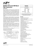
1
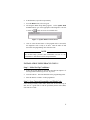
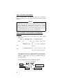
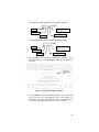
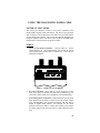
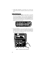
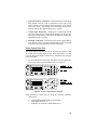
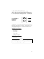
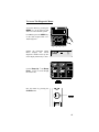
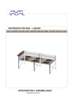
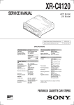
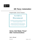
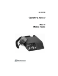
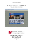
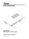
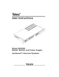
LBI-39135C Programming Manual MRK/ORION Diagnostic Radio Code (SPK654) R30A or later NOTICE! The software contained in this device is copyrighted by Com-Net Ericsson Critical Radio Systems, Inc. Unpublished rights are reserved under the copyright laws of the United States. This manual is published by Com-Net Ericsson Critical Radio Systems, Inc., without any warranty. Improvements and changes to this manual necessitated by typographical errors, inaccuracies of current information, or improvements to programs and/or equipment, may be made by Com-Net Ericsson Critical Radio Systems, Inc. at any time and without notice. Such changes will be incorporated into new editions of this manual. No part of this manual may be reproduced or transmitted in any form or by any means, electronic or mechanical, including photocopying and recording, for any purpose, without the express written permission of Com-Net Ericsson Critical Radio Systems, Inc. Copyright 1995-2000 Com-Net Ericsson Critical Radio Systems Inc. All rights reserved. 2 TABLE OF CONTENTS Page INTRODUCTION..........................................................................4 INSTALLATION PROCEDURE .................................................5 PROGRAMMER INSTALLATION ........................................5 Step 1 - Initial Set-Up Conditions:......................................5 Step 2 - Save Current Personality And Flash Code.............5 Step 3 - Create Test Personality..........................................5 Step 4 - Load The Test Personality And Diagnostic Software ..............................................................................6 EDACS-3/CONV-1 INSTALLATION.....................................7 Step 1 - Initial Set-Up Conditions:......................................7 Step 2 - Save Current Personality And Flash Code.............7 Step 3 - Create Test Personality..........................................8 Step 4 - Load The Test Personality And Diagnostic Software ..............................................................................8 USING THE DIAGNOSTIC RADIO CODE.............................11 POWER-UP TEST MODE.....................................................11 M-RK I..............................................................................11 M-RK II/M-RK II Scan ....................................................12 Orion Control Unit Test ....................................................13 RADIO OPERATION (M-RK RADIOS ONLY)...................15 Enabled General Features .................................................15 Disabled General Features ................................................15 Enabled Conventional Features.........................................16 Enabled Trunked Features ................................................16 DIAGNOSTIC RADIO MENU..............................................16 Editable Tx/Rx Diagnostic Variables................................18 Non-Editable Variables.....................................................19 3 INTRODUCTION The MRK/Orion Diagnostic Radio Code (SPK654) is specially designed radio code that provides diagnostic capability. The Diagnostic radio code is used as temporary replacement radio code for diagnostic purposes only. Using ProGrammer or EDACS-3/CONV-1 PC Programmer, the Diagnostic radio code installation procedure is the same as standard radio code. The Diagnostic radio code test features are: • Display/LED Verification (Power-Up Test Mode) • Keypad Verification • System/Group Verification • Volume Knob Verification • PTT, Option, Clear, Emergency Button Verification • Backlight Verification (M-RK II Only) • Diagnostic Variables NOTE This manual provides basic installation instructions for downloading the Diagnostic code into the radio using ProGrammer or EDACS3/CONV-1 PC Programmer. The On-Line Help System in ProGrammer or the Programmer manual for TQ-3374 and TQ-3367 should be used as the reference for system hook-up, PC Programming Software installation and operating instructions. The main focus of this manual is to provide diagnostic radio code operating instruction. 4 INSTALLATION PROCEDURE INSTALLATION USING ProGrammer Step 1 - Initial Set-Up Conditions: 1. Start ProGrammer. 2. From the Contents of the On-Line Help select Programming The Radio. Follow the System Hook-Up procedures described for the appropriate radio. 3. Turn the radio on. The radio should be in the programming mode. Step 2 - Save Current Personality And Flash Code If the current personality and/or radio (flash) code are not backed up to disk, now is a good time to read the personality and/or radio (flash) code and save to disk. In ProGrammer, from the Radio menu, select Read. WARNING The PC Programmer is used to WRITE the radio (flash) code to the radio. ProGrammmer (all versions) and EDACS-3/CONV-1 version 10 or later can also be used to READ the flash (code) out of the radio. Do not download the Diagnostic radio code to the radio, unless there is a backup copy (on floppy diskette or hard drive) of the current radio code loaded in the radio. Step 3 - Create Test Personality Create a test personality. The diagnostic radio code is designed to support personalities up to 2K bytes in size for all versions of radio hardware. NOTE Standard radio code supports radio personality files up to 14K bytes in size, depending on radio hardware and software version. Diagnostic test personalities should be created small. Any existing personality may be used as a test personality as long as the size of the file is approximately 2K bytes or less. Problems may occur if a personality is used that is larger than the recommended size. 5 Step 4 - Load The Test Personality And Diagnostic Software 1. Insert the Diagnostic Disk into the floppy drive. Using an appropriate file management system such as File Manager or Explorer, copy the appropriate diagnostic radio code file to the radio data folder defined in ProGrammer. The radio data folder is defined in the Directory Settings dialog box. By default, ProGrammer creates this folder in the following directory: c:\erictool\program\radbin The Diagnostic Radio Code diskette contains several diagnostic radio code files. Each file is applicable to a particular type of M-RK or ORION radio. The files are identified using the following method: For an M-RK II with Version 2 Hardware, use file: M2 T 30 2 99.BIN M-RK II Diag/Test Revision, this number is always 99 Test Radio Code Release R30 Version 2 Hardware For an M-RK I radio with Version 3 hardware, use file: M1 T 30 3 99.BIN M-RK I Diag/Test Revision, this number is always 99 Test Radio Code Release R30 Version 3 Hardware For an ORION radio with Version 3 hardware, use file: O T 30 3 99.BIN ORION Test Radio Code Release R30 6 Diag/Test Revision, this number is always 99 Version 3 Hardware 2. In ProGrammer, open the test personality. 3. From the Radio menu, select Program. 4. The Program Radio Setup dialog appears. In the Update With Version control, type in the appropriate radio diagnostic code file or select the button to browse for available files. Figure 1 - Update With Version Control 5. Click or select the OK button. If the program radio is successful, the diagnostic code is ready to be used. Turn the radio off and disconnect the programming cable from the radio. NOTE The On-Line Help provides more information on how to use ProGrammer to download code files and personalities. INSTALLATION USING EDACS-3/CONV-1 Step 1 - Initial Set-Up Conditions: 1. Follow the System Hook-Up procedures described in Chapter 2 of the Programmer manual (TQ-3374 or TQ-3367). 2. Turn the radio on. The radio should be in the programming mode. 3. Start the EDACS-3/CONV-1 radio programmer. Step 2 - Save Current Personality And Flash Code If the current personality and/or radio (flash) code are not backed up to disk, now is a good time to read the personality and/or radio (flash) code and save to disk. 7 Step 3 - Create Test Personality Create a test personality. The diagnostic radio code is designed to support personalities up to 2K bytes in size for all versions of radio hardware. NOTE Standard radio code supports radio personality files up to 14K bytes in size, depending on radio hardware and software version. Diagnostic test personalities should be created small. Any existing personality may be used as a test personality as long as the size of the file is approximately 2K bytes or less. Problems may occur if a personality is used that is larger than the recommended size. Step 4 - Load The Test Personality And Diagnostic Software 1. Insert the Diagnostic Disk into the floppy drive. From a DOS prompt type: copy where a:xxxxxxxx.bin ! a: xxxxxxxx.bin c:\ge\pool\bin is the computer floppy drive letter ! is the name of diagnostic radio code file c:\ge\pool\bin ! typical location of radio code files on the computer hard drive The Diagnostic Radio Code diskette contains several diagnostic radio code files. Each file is applicable to a particular type of M-RK or ORION radio. The files are identified using the following method: For an M-RK II with Version 2 Hardware, use file: M2 T 23 2 99.BIN M-RK II Diag/Test Revision, this number is always 99 Test Radio Code Group 23 8 Version 2 Hardware For an M-RK I radio with Version 3 hardware, use file: M1 T 23 3 99.BIN M-RK I Diag/Test Revision, this number is always 99 Test Radio Code Group 23 Version 3 Hardware For an ORION radio with Version 3 hardware, use file: O T 23 3 99.BIN ORION Diag/Test Revision, this number is always 99 Test Radio Code Group 23 2. Version 3 Hardware From the EDACS-3/CONV-1 PC Programming Software Current Personalities Screen, press F5 Progrm. Enter the test Personality file name. ••Ericsson GE Mobile Communications Inc.•••••••••••••••••••••••••••••••••••••••• •••••••••••••••••••••••••••••••••••••••••••••••••••••••••••••••••••••••••••••••• •• Personalities EDACS RADIO PROGRAMMER - 3 TQ-3374 •• •••••••••••••••••••••••••••••••••••••••••••••••••••••••••••••••••••••••••••••••• •••••••••••••••••••••••••••••••••••••••••••••••••••••••••••••••••••••••••••••••• •••••••••••••••••••••••••••••••••••••••••••••••••••••••••••••••••••••••••••••••• • • Program Radio • Enter Test • • • • • • • • Personality file • • • Personality name: • name • • • • • • • • • • • F1 - Program Personality. • • • • F2 - Programming options. • • • • F10 - Back - don't program radio. • • • • • • • • Please be sure the radio is connected • • • • to COM1 and that the radio is turned • • • • on before pressing F1. • • • • • • • Use the cursor• Enter the personality to program • • •••••••••••••••••••••••••••••••••••••••••••••••••••••••••••••••••••••••••••••••• F1 F2 F3 F4 F5 F6 F7 F8 F9 F10 Prog More Help Back Press F9 for field help, Shift F9 for window help Figure 2 - Program Personality Window 3. Press F2 More for more programming options. Tab to the Radio Code field and enter the Diagnostic radio code filename (as described earlier) that is applicable to the radio. Press F1 Prog to write the test personality and Diagnostic code to the radio. 9 ••Ericsson GE Mobile Communications Inc.•••••••••••••••••••••••••••••••••••••••• •••••••••••••••••••••••••••••••••••••••••••••••••••••••••••••••••••••••••••••••• •• Personalities EDACS RADIO PROGRAMMER - 3 TQ-3374 •• •••••••••••••••••••••••••••••••••••••••••••••••••••••••••••••••••••••••••••••••• •••••••••••••••••••••••••••••••••••••••••••••••••••••••••••••••••••••••••••••••• •••••••••••••••••••••••••••••••••••••••••••••••••••••••••••••••••••••••••••••••• • • Program Radio • • • • • • • • Personality name: Testpers • • Enter Diagnostic • • Radio Code: SAME • • Radio Code•File • • ADI Code: SAME • • • Unit ID.: SAME • Name Here• • • ORION Keypad File: NONE • • • • ORION CU ID: NONE • • • • • • • • F1 - Program F2 - Copy • • • • F10 - Back - don't program radio. • • • • • • • • Please be sure the radio is connected to COMM1 • • • • and the radio is turned on before Pressing F1. • • • Use the• Enter the personality to program • • •••••••••••••••••••••••••••••••••••••••••••••••••••••••••••••••••••••••••••••••• F1 F2 F3 F4 F5 F6 F7 F8 F9 F10 Prog File Help Back Press F9 for field help, Shift F9 for window help Figure 3 - Program Radio (More) Window 4. 10 If the program radio is successful, the diagnostic code is ready to be used. Turn the radio off and disconnect the programming cable from the radio. USING THE DIAGNOSTIC RADIO CODE POWER-UP TEST MODE The Power-Up Test Mode is used to verify proper operation of the display/LEDs, keypad, knobs and buttons. The Power-Up Test Mode does not apply to Orion radios due to the built in test provided with the Orion Control Unit Software. This section describes the procedure for using the diagnostic radio code Power-Up Test Mode for MRK radios and the built in control unit test for the Orion radios. M-RK I 1. Power-Up Test Mode Verification . Turn the radio on. All the LEDs should be lit. After approximately one second the current system/group knob position will be indicated by a tone and the LEDs will extinguish. Figure 3 - M-RK I Power-Up Display 2. Key pad verification. Press each key on the keypad to test the keys. Every key press should cause the radio to sound the key-ack tone at the current volume level and light the corresponding LED. 3. System/Group Knob Verification. Repositioning the system/group knob should cause the radio to sound a tone at the current volume level corresponding to the current knob position. The tone will be higher for higher knob position. For example, the first knob position will cause the radio to sound a low frequency tone and the last knob position will cause the radio to sound a high frequency tone. 11 4. Volume Knob Verification. Repositioning of the Volume knob should cause the radio to sound the key-ack tone at the new volume level. M-RK II/M-RK II Scan 1. Power-Up Test Mode Verification. Turn the radio on. All pixels and icons on the display should be lit at the power up contrast level set by the PC Programmer. Next, the current system/group knob position should be indicated on the bottom line along with the keyack tone at the current volume level. After approximately one (1) second, the icons as well as the current system/group knob position display message should extinguish. Figure 4 - M-RK II Power-Up Display 2. Key Pad Verification. Every key press should cause the radio to sound the key-ack tone at the current volume level and display (on the top line) the name of the key or the label that is printed on the key. The top line of the display will return to the fill pixel display after approximately one (1) second. Figure 5 - M-RK II Key Pad Verification 12 3. System/Group Knob Verification. Repositioning the system/group knob should cause the radio to sound the key-ack tone at the current volume level and display the knob position on the bottom level of the display. The bottom line of the display returns to the full pixel display after approximately one (1) second. 4. Volume Knob Verification. Changing the Volume knob should cause the volume level to change and be displayed on the top line. The top line of the display will return to the full pixel display after approximately one (1) second. 5. Backlight Verification. Pressing the PTT button, Option button, Clear button or any key on the keypad should cause the backlight to light up at the level indicated by the PC Programmer. Orion Control Unit Test The Orion Control Unit has built into the Software the capacity to test the control unit's keypad, display, LEDs, knobs and buttons. For this reason the Diagnostic Radio Code Power-Up Test Mode does not apply to the Orion radio. 1. To Access the Orion Control Unit Test Mode, press the appropriate two (2) keys on the keypad simultaneously. See Figure 6. Figure 6 - Access Control Unit Test Mode Upon entering the control unit test mode, the following conditions should occur: • • • copyright information should be on the display all keylights should be on the BUSY, SCAN and TX LEDs should be on 13 1. Use the Up1 and Down1 to control the display intensity. Use the Up2 and Down2 to control the backlight intensity. 2. Test the keys on the keypad by pressing each key. The keylight above each key should extinguish as the key is pressed. 3. After all the keylights are extinguished, the BUSY, SCAN, and TX LEDs should go out. 4. The volume, light intensity and rotary selector knob information along with software version should appear on the display. 5. Pressing keys 01 and 02 will display the control unit's network ID and RQST line configuration. Pressing the 01 and 02 keys will also result in the Federal SS2000 siren and lights interface to send out a two byte bit pattern. NOTE In the control unit test mode, the control unit will not communicate with any network devices. 14 RADIO OPERATION (M-RK Radios Only) When the radio is powered up with the diagnostic code, the radio is in the Power-Up Test Mode as described previously. To exit the PowerUp Test Mode and enter the Diagnostic Test Load Mode (normal operation with limited features): press the OPTION and CLEAR buttons simultaneously The Diagnostic Test Load Mode allows the radio to function as a normal radio with a limited set of features. The following is a list of enabled and disabled features for Conventional and Trunked systems. Enabled General Features ⇒ Diagnostic Variables Menu ⇒ Battery Feature ⇒ System Change ⇒ Volume Adjust ⇒ Group/Channel Change Disabled General Features ⇒ Regular Menu NOTE The radio may power-up with a temporary error message, if the radio does not have Aegis hardware or if Aegis software has not been loaded. This warning message can be ignored. 15 Enabled Conventional Features ⇒ Tone Channel Guard/Digital Channel Guard Encode/Decode ⇒ Transmit And Receive ⇒ DTMF Encoding During Transmit ⇒ Channel Scanning ⇒ Monitor ⇒ Squelch Adjust Enabled Trunked Features ⇒ Clear Voice Group Calls (Transmit and Receive) ⇒ Aegis Group Calls (Transmit and Receive) DIAGNOSTIC RADIO MENU The Diagnotic Radio Menu is only available for M-RK II, M-RK II Scan and Orion radios. For radios with version 1 or 2 hardware, there are twelve (12) diagnostic menu items that affect and/or reflect various aspects of the radio. For radios with version 3 hardware, there are nineteen (19) diagnostic menu items that affect and/or reflect various aspects of the radio. Five (5) of the menu items are transmit/receive diagnostic variables that can be edited, the remaining are for display only. With the exception of DRSSI (, all of the diagnostic menu items must be accessed from a Conventional Systems only. DRSSI must be accessed while on a Trunked System only. See Table 1 below. Table 1 - Diagnostic Menu Diagnostic Menu Items Version 1 and 2 Hardware Version 3 Hardware Total 12 19 Non-Editable 7 14 Editable 5 5 Available From Conventional System 11 18 Available From A Trunked System 1 1 16 To Access The Diagnostic Menu: Access the Menu by pressing the MENU key on the radio keypad while on a Conventional System. For DRSSI, press the MENU key on the radio keypad while on a Trunked System Initially the Diagnostic Radio Menu displays the current diagnostic variable on the top line of the display followed by a value Use the Ramp Up " and Ramp Down # keys to scroll through the menu items Exit the menus by pressing the CLEAR button. 17 Editable Tx/Rx Diagnostic Variables There are five (5) editable diagnostic variables in the Diagnostic menu. The radio operates according to the values of the diagnostic variables while in the Diagnostic menu. After exiting the menu (by pressing CLEAR) the radio operation is no longer affected by the values of the diagnostic variables. To modify or change the value of an editable diagnostic variable, press the MENU key when the desired variable is being displayed. This puts the radio in the Entry Mode. Enter the new value directly from the keypad or by using the Ramp Up " and Ramp Down # keys to increment or decrement the value by one. The new value is displayed on the bottom line. The OPTION button can be used to backspace for editing. Pressing the MENU key again causes the diagnostic variable to take the new value (if it is in the valid range). The following diagnostic menu items can be edited: NOTE The PWR, DEV and SQWT variables from the Diagnostic Menu can be used to Calibrate Tracking Data. The value displayed for each of these variables represent temporary equivalent Tracking Data values. The values in these variables can be changed while making Power, Deviation, or Squelch measurements which will assist in finding the desired tracking data values. As stated before, the radio only operates according to these variables while in the Diagnostic Menu. THE TRACKING DATA FOR THE RADIO CANNOT BE CHANGED USING THE DIAGNOSTIC RADIO CODE. Once the desired values are found, the Tracking Data must be changed using the PC Programmer. Refer to the Tracking Data section in the appropriate Service Manual. 18 DAT - Data "0" "1" "2" "3" "4" "5" Valid Range: Tx Clear Voice on current channel when PTT is pressed Tx Random High Speed Data on current channel when PTT is pressed Tx Random G-STAR on current channel when PTT is pressed Tx Dotting on current channel when PTT is pressed Tx 9-bit Pseudo High Speed Data pattern when PTT is pressed Tx 11-bit Pseudo Random Speed Data pattern when PTT is pressed BAUD - High Speed Data Baud Rate "0" "1" 0-5 Valid Range: 0-1 Use 4800 Baud when transmitting Use 9600 Baud when transmitting PWR - Power Level Override Valid Range: 0-255 When PTT is pressed, radio will transmit on current channel at corresponding Power Level (does not reflect a specific wattage, but a value relative to the particular radio capabilities). DEV - Tx Deviation Override Valid Range: 0-63 When PTT is pressed, radio will transmit on current channel with corresponding Deviation (does not reflect a specific deviation, but a value relative to the particular radio capabilities). SQWT - Squelch Override Valid Range: 0-255 Mute/Unmute speaker on current channel at corresponding squelch level (does not reflect a specific squelch level, but a value relative to the particular radio capabilities). Non-Editable Variables All of these variables display a value between 0 and 255 that is read from the radio. Some variables have a limit that will not be exceeded. For example, RSSI will never indicate a value greater than 130. The following is a list of the Non-Editable Variables: RSSI Strength Of Current Signal DRSSI Quality of the received Signal SQRD Squelch Level of Current Signal UDC Resistor Value of UDC (see page 21) VOL Current Volume Knob Value BATT Battery Level BRDT Board Type 19 The following non-editable variables apply to Version 3 radios: PRS NAME Name of personality FLSH VER Group number, hardware version number and revision of radio flash software COPYRIGHT Com-Net Ericsson copyright information RCP VER Version of RCP code in the radio ICP VER Version of ICP code in the radio ADI ROM ADI ROM code version in the radio ADI NON ADI RAM code version in the radio 20 UDC Devices And Programming Resistor The M-RK radio must be interfaced with a variety of accessories with a minimum number of connections. The M-RK software senses the type of accessory connected to the radio by measuring the resistance value connected to pin 8 (UDC SENS IN). The function of the remaining pins are then defined by the software. The following table provides the UDC devices and the corresponding resistor value and the UDC value that is displayed: Device Value Displayed Number (0-255) 0 0-35 Resistor Value ±2.5% <100 ohms 1 36-50 1270 Reserved 2 51-55 1540 PC Data Cable 3 56-60 1870 Reserved 4 61-66 2210 Key Loader Cable 5 67-72 2670 Reserved 6 73-79 3160 Vehicular Charger with Orion Control Unit 7 80-87 3740 Speaker/MIC with and without Antenna 8 88-95 4420 Earphone 9 96-105 5360 Vehicular Charger, Normal Display 10 106-115 6490 Vehicular Charger, Inverted Display 11 116-126 7680 External Microphone 12 127-138 9530 Speaker/MIC "B" 13 139-151 11.8K Reserved 14 152-166 15.0K Reserved 15 167-181 20.0K Reserved 16 182-229 27.4K Reserved 17 230-255 Infinity Normal M-RK Operation Accessory Type Programming Cable 21 NOTES 22 NOTES 23 Com-Net Ericsson Critical Radio Systems, Inc. P.O. Box 2000 Lynchburg, Virginia 24501 1-800-528-7711 (Outside USA, 804-592-7711) Printed in U.S.A.