1
xx
ZZZ
AFG2021
Arbitrary Function Generator
Programmer Manual
*P077058701*
077-0587-01
xx
ZZZ
AFG2021
Arbitrary Function Generator
Programmer Manual
www.tektronix.com
077-0587-01
Copyright © Tektronix. All rights reserved. Licensed software products are owned by Tektronix or its subsidiaries
or suppliers, and are protected by national copyright laws and international treaty provisions.
Tektronix products are covered by U.S. and foreign patents, issued and pending. Information in this publication
supersedes that in all previously published material. Specifications and price change privileges reserved.
TEKTRONIX and TEK are registered trademarks of Tektronix, Inc.
Contacting Tektronix
Tektronix, Inc.
14150 SW Karl Braun Drive
P.O. Box 500
Beaverton, OR 97077
USA
For product information, sales, service, and technical support:
In North America, call 1-800-833-9200.
Worldwide, visit www.tektronix.com to find contacts in your area.
Table of Contents
Preface ..............................................................................................................
Documentation ................................................................................................
iii
iii
Getting Started
Getting Started ....................................................................................................
Overview of the Manual ....................................................................................
Connecting the Interface ....................................................................................
Using the GPIB Port.........................................................................................
Setting the GPIB Address...................................................................................
Using TekVISA ..............................................................................................
1-1
1-1
1-2
1-3
1-4
1-4
Syntax and Commands
Syntax and Commands........................................................................................... 2-1
Command Syntax................................................................................................. 2-2
Backus-Naur Form Definition .............................................................................. 2-2
Command and Query Structure ............................................................................ 2-2
SCPI Commands and Queries .............................................................................. 2-4
IEEE 488.2 Common Commands.......................................................................... 2-9
Command Groups .............................................................................................. 2-11
Command Descriptions ........................................................................................ 2-17
Status and Events
Status and Events ................................................................................................. 3-1
Status Reporting Structure .................................................................................. 3-1
Registers ...................................................................................................... 3-3
Queues ...................................................................................................... 3-10
Messages and Codes....................................................................................... 3-11
Programming Examples
Programming Examples .........................................................................................
4-1
Appendices
Appendix A: SCPI Conformance Information ...............................................................
AFG2021 Arbitrary Function Generator Programmer Manual
A-1
i
Table of Contents
ii
AFG2021 Arbitrary Function Generator Programmer Manual
Preface
This manual provides operating information for the AFG2021 Arbitrary Function
Generator.
The manual consists of the following sections:
Getting Started covers operating principles of the instrument, which helps you
understand how your generator operates.
Syntax and Commands defines the command syntax and processing
conventions, describes command notation.
Status and Events explains the status information and event messages reported
by the instrument.
Programming Examples contains remote interface application programs to
help you develop programs for your application.
Appendix A: SCPI Conformance Information contains a list of commands
and SCPI information.
Documentation
In addition to this AFG2021 Arbitrary Function Generator Programmer Manual,
the following documentation is available for this instrument:
AFG2021 Arbitrary Function Generator Quick Start User Manual. The quick start
user manual provides information on installation, general features, operating the
instrument, and user interface.
Built in Help System. The built-in help system that is integrated with the User
Interface application that ships with this instrument.
AFG2021 Arbitrary Function Generator Specifications and Performance Verification
Technical Reference. The technical reference provides information on instrument
specifications and procedures for performance verification.
AFG2021 Arbitrary Function Generator Service Manual. The service manual
includes procedures to service the instrument to the module level. The manual
also includes adjustment procedures, theory of operation information, and a list of
replaceable parts.
AFG2021 Arbitrary Function Generator Programmer Manual
iii
Preface
iv
AFG2021 Arbitrary Function Generator Programmer Manual
Getting Started
Getting Started
To help you get started with programming the instrument, this section includes the
following subsections
Overview of the Manual
Summarizes each major section of this manual.
Connecting the Interface
Describes how to physically connect the instrument to a controller.
Using GPIB Port
Describes how to use the GPIB port.
Setting the GPIB Address
Describes how to set the GPIB parameters from the front panel.
Using TekVISA
Describes how to use the TekVISA communication protocol.
Overview of the Manual
The information contained in each major section of this manual is described below.
Syntax and Commands
Syntax and Commands, describes the structure and content of the messages your
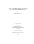
program sends to the instrument. The following figure shows command parts as
described in the Command Syntax subsection.
Figure 1-1: Command parts
Section 2 also describes the effect of each command and provides examples
of how you might use it. The Command Groups subsection provides lists by
functional areas. The commands are listed alphabetically in the Command
Descriptions section.
AFG2021 Arbitrary Function Generator Programmer Manual
1-1
Getting Started
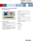
Figure 1-2: Functional groupings and an alphabetical list of commands
Status and Events
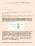
The program may request information from the instrument. The instrument
provides information in the form of status and error messages. The following
figure illustrates the basic operation of this system. Section 3, Status and Events,
describes how to get status or event information from the program and details
the event and error messages.
Figure 1-3: Event-driven program
Connecting the Interface
The AFG2021 with Option GL has a 24-pin GPIB connector on its rear panel, as
shown in the following figure. (The AFG2021 base model provides a USB port
only.) This connector has a D-type shell and conforms to IEEE Std 488.1-1987.
Attach an IEEE Std 488.1-1987 GPIB cable (Tektronix part number 012-0991-00)
to this connector.
1-2
AFG2021 Arbitrary Function Generator Programmer Manual
Getting Started
Figure 1-4: GPIB connector (rear panel with Option GL only )
Using the GPIB Port
The instrument has Talker/Listener functions through which it can communicate
with other devices, as well as the external controller, located on the bus.
Figure 1-5: GPIB connection
AFG2021 Arbitrary Function Generator Programmer Manual
1-3
Getting Started
GPIB Requirements
Observe the following rules when you use your instrument with a GPIB network
Assign a unique device address to each device on the bus. No two devices
can share the same device address.
Do not connect more than 15 devices to any one bus.
Connect one device for every 2 m (6 ft) of cable used.
Do not use more than 20 m (65 ft) of cable to connect devices to a bus.
Turn on at least 2/3 of the devices on the network while using the network.
Connect the devices on the network in a star or linear configuration, as shown
in the following figure. Do not use loop or parallel configurations.
Figure 1-6: Typical GPIB network configurations
Setting the GPIB Address
When you use the GPIB port to communicate with an external controller, follow
these steps to set the address of the instrument.
1. Press the Utility button.
2. Press the I/O Interface button.
3. Press the GPIB button.
4. Press the Address button.
5. Turn the general purpose knob to set the GPIB Address.
6. Press the Return to up menu button when you have set the GPIB address to
save the setting.
NOTE. The GPIB address cannot be initialized by the *RST command.
Using TekVISA
TekVISA is Tektronix implementation of VISA (Virtual Instrument Software
Architecture), an industry-standard communication protocol. VISA provides
1-4
AFG2021 Arbitrary Function Generator Programmer Manual
Getting Started
a common standard for software developers so that software from multiple
vendors, such as instrument drivers, can run on the same platform. TekVISA
is industry-compliant software, available with selected Tektronix instruments.
You can use this software to write (or draw) interoperable instrument drivers in
a variety of Application Development Environments (ADEs). It implements
a subset of Version 2.2 of the VISA specification for controlling GPIB and
serial (RS-232) instrument interfaces locally or remotely via an Ethernet LAN
connection.
Installation
Use an internet browser to access the Tektronix Web site (www.tektronix.com)
and download the current TekVISA to your PC. Unzip the downloaded file in a
temporary directory of your choice and run Setup.exe.
NOTE. The details on TekVISA concepts and operations are explained in the
TekVISA Programmer Manual that can be also found on the Tektronix Web site.
AFG2021 Arbitrary Function Generator Programmer Manual
1-5
Getting Started
1-6
AFG2021 Arbitrary Function Generator Programmer Manual
Syntax and Commands
Syntax and Commands
This section provides the following information:
Command Syntax defines the command syntax and processing conventions.
Command Groups describes command groups which lists the commands
by function.
Command Descriptions describes the notation of each of the commands in
alphabetical order.
AFG2021 Arbitrary Function Generator Programmer Manual
2-1
Command Syntax
Command Syntax
You can control the operations and functions of the instrument through the
GPIB interface using commands and queries. The related topics listed below
describe the syntax of these commands and queries. The topics also describe the
conventions that the instrument uses to process them. See Command Groups
(See page 2-11.)for a listing of the commands by command group, or use the
index to locate a specific command.
Backus-Naur Form Definition
This manual may describe commands and queries using the Backus-Naur Form
(BNF) notation. The following table defines the standard BNF symbols.
Table 2-1: BNF symbols and meanings
Symbol
< >
Meaning
:=
Is defined as
|
Exclusive OR
{ }
Group; one element is required
[ ]
.. .
Optional; can be omitted
( )
Comment
Defined element
Previous element(s) may be repeated
Command and Query Structure
Commands consist of set commands and query commands (usually simply called
commands and queries). Commands change instrument settings or perform a
specific action. Queries cause the instrument to return data and information about
its status.
Most commands have both a set form and a query form. The query form of
the command is the same as the set form except that it ends with a question
mark. For example, the set command DISPlay:BRIGhtness has a query form
DISPlay:BRIGhtness?. Not all commands have both a set and a query form;
some commands are set only and some are query only.
A few commands do both a set and query action. For example, the *CAL?
command runs a self-calibration program on the instrument, then returns the
result of the calibration.
A command message is a command or query name, followed by any information
the instrument needs to execute the command or query. Command messages
consist of five element types.
2-2
AFG2021 Arbitrary Function Generator Programmer Manual
Command Syntax
Table 2-2: Command message elements
Symbol
Meaning
<Header>
The basic command name. If the header ends with a question mark, the
command is a query. The header may begin with a colon (:) character;
if the command is concatenated with other commands the beginning
colon is required. The beginning colon can never be used with command
headers beginning with a star (*).
<Mnemonic>
A header subfunction. Some command headers have only one mnemonic.
If a command header has multiple mnemonics, they are always separated
from each other by a colon (:) character.
<Argument>
A quantity, quality, restriction, or limit associated with the header. Not
all commands have an argument, while other commands have multiple
arguments. Arguments are separated from the header by a <Space>.
Arguments are separated from each other by a <Comma>.
<Comma>
A single comma between arguments of multiple-argument commands. It
may optionally have white space characters before and after the comma.
<Space>
A white space character between command header and argument. It may
optionally consist of multiple white space characters.
The following figure shows the five command message elements.
Commands. Commands cause the instrument to perform a specific function or
change one of its settings. Commands have the structure:
[:]<Header>[<Space><Argument>[<Comma><Argument>]...]
A command header is made up of one or more mnemonics arranged in a
hierarchical or tree structure. The first mnemonic is the base or root of the tree and
each subsequent mnemonic is a level or branch of the previous one. Commands at
a higher level in the tree may affect those at a lower level. The leading colon (:)
always returns you to the base of the command tree.
Queries. Queries cause the instrument to return information about its status or
settings. Queries have the structure:
[:]<Header>?
[:]<Header>?[<Space><Argument>[<Comma><Argument>]...]
AFG2021 Arbitrary Function Generator Programmer Manual
2-3
Command Syntax
You can specify a query command at any level within the command tree unless
otherwise noted. These branch queries return information about all the mnemonics
below the specified branch or level.
Query Responses. When a query is sent to the instrument, only the values are
returned. When the returned value is a mnemonic, it is noted in abbreviated
format, as shown in the following table.(See Table 2-3.)
Table 2-3: Query response examples
Command Entry
Symbol
Meaning
SOURce:PULSe:DCYcle?
50.0
OUTPut:POLarity?
NORM
Follow these general rules when entering commands:
Enter commands in upper or lower case.
You can precede any command with white space characters. White space
characters include any combination of the ASCII control characters 00 through
09 and 0B through 20 hexadecimal (0 through 9 and 11 through 32 decimal).
The instrument ignores commands that consists of just a combination of white
space characters and line feeds.
SCPI Commands and Queries
The instrument uses a command language based on the SCPI standard. The SCPI
(Standard Commands for Programmable Instruments) standard was created by
a consortium to provide guidelines for remote programming of instruments.
These guidelines provide a consistent programming environment for instrument
control and data transfer. This environment uses defined programming messages,
instrument responses and data formats that operate across all SCPI instruments,
regardless of manufacturer.
The SCPI language is based on a hierarchical or tree structure as shown in the
following figure that represents a subsystem. The top level of the tree is the root
node; it is followed by one or more lower-level nodes.
Figure 2-1: Example of SCPI subsystem hierarchy tree
2-4
AFG2021 Arbitrary Function Generator Programmer Manual
Command Syntax
You can create commands and queries from these subsystem hierarchy trees.
Commands specify actions for the instrument to perform. Queries return
measurement data and information about parameter settings.
Creating Commands
SCPI commands are created by stringing together the nodes of a subsystem
hierarchy and separating each node by a colon.
In the figure above, TRIGger is the root node and SEQuence, SLOPe, SOURce,
and TIMer are lower level nodes. To create a SCPI command, start with the root
node TRIGger and move down the tree structure adding nodes until you reach the
end of a branch. Most commands and some queries have parameters; you must
include a value for these parameters. If you specify a parameter value that is out
of range, the parameter will be set to a default value. The command descriptions,
list the valid values for all parameters.
For example, TRIGger:SEQuence:SOURce EXTernal is a valid SCPI command
created from the hierarchy tree. (See Figure 2-1.)
Creating Queries
To create a query, start at the root node of a tree structure, move down to the end of
a branch, and add a question mark. TRIGger:SEQuence:SOURce? is an example
of a valid SCPI query using the hierarchy tree in the figure. (See Figure 2-1.)
Query Responses
The query causes the instrument to return information about its status or settings.
When a query is sent to the instrument, only the values are returned. When the
returned value is a mnemonic, it is noted in abbreviated format. (See Table 2-3.)
Parameter Types
Every parameter in the command and query descriptions is of a specified type.
(See Table 2-4.) The parameters are enclosed in brackets, such as <value>.
The parameter type is listed after the parameter and is enclosed in parentheses,
for example, (boolean). Some parameter types are defined specifically for the
instrument command set and some are defined by SCPI.
Table 2-4: Parameter types used in syntax descriptions
Parameter type
arbitrary
block 1
Description
Example
A specified length of
arbitrary data
#512234xxxxx . . . where
5 indicates that the following
5 digits (12234) specify the
length of the data in bytes;
xxxxx ... indicates the data
or
#0xxxxx...<LF><&EOI>
boolean
Boolean numbers or values
AFG2021 Arbitrary Function Generator Programmer Manual
ON or ≠ 0
OFF or 0
2-5
Command Syntax
Table 2-4: Parameter types used in syntax descriptions (cont.)
Parameter type
Description
Example
discrete
A list of specific values
MIN, MAX
binary
Binary numbers
#B0110
octal
Octal numbers
#Q57, #Q3
hexadecimal 2
Hexadecimal numbers
(0-9, A, B, C, D, E, F)
#HAA, #H1
NR1 2 numeric
Integers
0, 1, 15, -1
NR2 2 3 numeric
Decimal numbers
1.2, 3.141516, -6.5
NR3 2
numeric
Floating point numbers
3.1415E-9, -16.1E5
NRf 2
numeric
Flexible decimal number that
may be type NR1, NR2 or NR3
See NR1, NR2, and NR3
examples
Alphanumeric characters (must
be within quotation marks)
"Testing 1, 2, 3"
string 4
1
Defined in ANSI/IEEE 488.2 as "Definite Length Arbitrary Block Response Data."
2
An ANSI/IEEE 488.2-1992-defined parameter type.
3
Some commands and queries will accept an octal or hexadecimal value even though the parameter type is
defined as NR1.
4
Defined in ANSI/IEEE 488.2 as "String Response Data."
Special Characters
The Line Feed (LF) character or the New Line (NL) character (ASCII 10), and all
characters in the range of ASCII 127-255 are defined as special characters. These
characters are used in arbitrary block arguments only; using these characters in
other parts of any command yields unpredictable results.
Abbreviating Commands,
Queries, and Parameters
You can abbreviate most SCPI commands, queries, and parameters to an accepted
short form. This manual shows these short forms as a combination of upper and
lower case letters. The upper case letters indicate the accepted short form of a
command. As shown in the following figure, you can create a short form by
using only the upper case letters. The accepted short form and the long form are
equivalent and request the same action of the instrument.
Figure 2-2: Example of abbreviating a command
2-6
AFG2021 Arbitrary Function Generator Programmer Manual
Command Syntax
NOTE. The numeric suffix of a command or query may be included in either the
long form or short form; the instrument will default to "1" if no suffix is used.
Chaining Commands and
Queries
You can chain several commands or queries together into a single message. To
create a chained message, first create a command or query, add a semicolon
(;), and then add more commands or queries and semicolons until the message
is complete. If the command following a semicolon is a root node, precede it
with a colon (:). The following figure illustrates a chained message consisting
of several commands and queries. The single chained message should end in a
command or query, not a semicolon. Responses to any queries in your message
are separated by semicolons.
Figure 2-3: Example of chaining commands and queries
If a command or query has the same root and lower-level nodes as the previous
command or query, you can omit these nodes. In the following figure, the second
command has the same root node (TRIGger:SEQuence) as the first command,
so these nodes can be omitted.
Figure 2-4: Example of omitting root and lower-level nodes in a chained message
Unit and SI Prefix
If the decimal numeric argument refers to amplitude, frequency, or time, you can
express it using SI units instead of using the scaled explicit point input value
format <NR3>. (SI units are units that conform to the Systeme International
d'Unites standard.) For example, you can use the input format 200 mV or 1.0 MHz
instead of 200.0E-3 or 1.0E+6, respectively, to specify voltage or frequency.
AFG2021 Arbitrary Function Generator Programmer Manual
2-7
Command Syntax
The following table lists the available units.
Table 2-5: Available units
Symbol
Meaning
dB
decibel (relative amplitude)
dBm
decibel (absolute amplitude)
DEG
degree (phase)
Hz
hertz (frequency)
PCT
s
second (time)
V
volt
percent (%)
You can omit a unit in a command, but you must include the unit when using a SI
prefix. For example, frequency of 15 MHz can be described as follows
15.0E6, 1.5E7Hz, 15000000, 15000000Hz, 15MHz, etc.
("15M" is not allowed.)
General rules for using
SCPI commands
Here are three general rules for using SCPI commands, queries, and parameters:
You can use single (‘ ’) or double (“ ”) quotation marks for quoted strings, but
you cannot use both types of quotation marks for the same string.
correct
"This string uses quotation marks correctly."
correct
‘This string also uses quotation marks correctly.'
incorrect
"This string does not use quotation marks correctly.'
You can use upper case, lower case, or a mixture of both cases for all
commands, queries, and parameters.
:SOURCE:FREQUENCY 10MHZ
is the same as
:source:frequency 100mhz
and
SOURCE:frequency 10MHZ
NOTE. Literal strings (quoted) are case sensitive, for example, file names.
No embedded spaces are allowed between or within nodes.
2-8
correct
:OUTPUT:FILTER:LPASS:FREQUENCY 200MHZ
incorrect
:OUTPUT: FILTER: LPASS:FREQUENCY 200MHZ
AFG2021 Arbitrary Function Generator Programmer Manual
Command Syntax
IEEE 488.2 Common Commands
Description
ANSI/IEEE Standard 488.2 defines the codes, formats, protocols, and usage of
common commands and queries used on the interface between the controller and
the instruments. The instrument complies with this standard.
Command and Query
Structure
The syntax for an IEEE 488.2 common command is an asterisk (*) followed by a
command and, optionally, a space and parameter value. The syntax for an IEEE
488.2 common query is an asterisk (*) followed by a query and a question mark.
All of the common commands and queries are listed in the last part of the Syntax
and Commands section. The following are examples of common commands:
*ESE 16
*CLS
The following are examples of common queries
*ESR?
*IDN?
AFG2021 Arbitrary Function Generator Programmer Manual
2-9
Command Syntax
2-10
AFG2021 Arbitrary Function Generator Programmer Manual
Command Groups
This section lists the commands organized by functional group. The Command
Descriptions section lists all commands alphabetically. (See page 2-17.)
Calibration and Diagnostic Commands. Calibration and Diagnostic commands
let you initiate the instrument self-calibration routines and examine the results
of diagnostic tests. The following table lists the Calibration and Diagnostic
commands.
Table 2-6: Calibration and Diagnostic commands
Header
Description
*CAL?
Perform self-calibration and return result
status
CALibration[:ALL]
Perform self-calibration
DIAGnostic[:ALL]
Perform self-test
*TST?
Perform self-test and return result status
Display Commands. Display commands let you change the graticule style,
displayed brightness, and other display attributes. The following table lists and
describes the Display commands.
Table 2-7: Display commands
Header
Description
DISPlay:BRIGhtness
Set/query the LCD display brightness
DISPlay:SAVer:IMMediate
Set screen saver.
DISPlay:SAVer[:STATe]
Set/query the screen saver settings
DISPlay[:WINDow]:TEXT[:DATA]
Set/query the text message display
DISPlay[:WINDow]:TEXT:CLEar
Delete text message
Memory Commands. Memory commands let you change setup memory attributes.
The following table lists and describes the Memory commands.
Table 2-8: Memory commands
Header
Description
MEMory:STATe:DELete
Delete the setup memory
MEMory:STATe:LOCK
Set/query the lock of setup memory overwrite
and deletion
MEMory:STATe:RECall:AUTo
Set/query the recall of last set memory
MEMory:STATe:VALid?
Query the availability of setup memory
*RCL
Recall instrument setting from setup memory
*SAV
Save instrument setting to setup memory
AFG2021 Arbitrary Function Generator Programmer Manual
2-11
Command Groups
Mass Memory Commands. Mass Memory commands let you change mass
memory attributes. The following table lists and describes the Mass Memory
commands.
Table 2-9: Mass Memory commands
Header
Description
MMEMory:CATalog?
Query the status of mass memory
MMEMory:CDIRectory
Set/query current directory
MMEMory:DELete
Delete file or directory in mass memory
MMEMory:LOAD:STATe
Copy instrument setting in mass memory to
setup memory
MMEMory:LOAD:TRACe
Copy waveform data file in mass memory to
edit memory
MMEMory:LOCK[:STATe]
Set/query the lock of mass memory overwrite
and deletion
MMEMory:MDIRectory
Create directory in mass memory
MMEMory:STORe:STATe
Save the setup memory status to mass
memory
MMEMory:STORe:TRACe
Save waveform data file in edit memory to
mass memory
Output Commands. Output commands let you set output attributes. The following
table lists and describes the Output commands.
Table 2-10: Output commands
Header
Description
OUTPut[1]:IMPedance
Set/query impedance
OUTPut[1]:POLarity
Set/query polarity
OUTPut[1][:STATe]
Set/query output on or off
OUTPut:TRIGger:MODE
Set/query the mode of Trigger Output
Source Commands. Source commands let you set waveform output parameters.
The following table lists and describes the Source commands.
Table 2-11: Source commands
2-12
Header
Description
[SOURce]:ROSCillator:SOURce
Set/query clock reference input
[SOURce[1]]:AM[:DEPTh]
Set/query amplitude modulation depth
[SOURce[1]]:AM:INTernal:FREQuency
Set/query internal modulation frequency
[SOURce[1]]:AM:INTernal:FUNCtion
Set/query modulation waveform setting
[SOURce[1]]:AM:INTernal:FUNCtion:EFILe
Set/query EFILe setting
[SOURce[1]]:AM:SOURce
Set/query amplitude modulation source
AFG2021 Arbitrary Function Generator Programmer Manual
Command Groups
Table 2-11: Source commands (cont.)
Header
Description
[SOURce[1]]:AM:STATe
Set/query amplitude modulation status
[SOURce[1]]:BURSt:MODE
Set/query burst mode
[SOURce[1]]:BURSt:NCYCles
Set/query burst mode waveform output cycle
[SOURce[1]]:BURSt[:STATe]
Set/query burst mode status
[SOURce[1]]:BURSt:TDELay
Set/query burst mode trigger delay time
[SOURce[1]]:COMBine:FEED
Set/query internal noise
[SOURce[1]]:FM[:DEViation]
Set/query frequency deviation
[SOURce[1]]:FM:INTernal:FREQuency
Set/query internal modulation frequency
[SOURce[1]]:FM:INTernal:FUNCtion
Set/query internal modulation waveform
[SOURce[1]]:FM:INTernal:FUNCtion:EFILe
Set/query EFILe setting
[SOURce[1]]:FM:SOURce
Set/query frequency modulation source
[SOURce[1]]:FM:STATe
Set/query frequency modulation status
[SOURce[1]]:FREQuency:CENTer
Set/query center frequency
[SOURce[1]]:FREQuency[:CW|:FIXed]
Set/query output waveform frequency
[SOURce[1]]:FREQuency:MODE
Set/query sweep status
[SOURce[1]]:FREQuency:SPAN
Set/query sweep frequency span
[SOURce[1]]:FREQuency:STARt
Set/query sweep start frequency
[SOURce[1]]:FREQuency:STOP
Set/query sweep stop frequency
[SOURce[1]]:FSKey[:FREQuency]
Set/query FSK hop frequency
[SOURce[1]]:FSKey:INTernal:RATE
Set/query FSK internal modulation rate
[SOURce[1]]:FSKey:SOURce
Set/query FSK source
[SOURce[1]]:FSKey:STATe
Set/query FSK status
[SOURce[1]]:FUNCtion:EFILe
Set/query EFILe name
[SOURce[1]]:FUNCtion:RAMP:SYMMetry
Set/query ramp waveform symmetry
[SOURce[1]]:FUNCtion[:SHAPe]
Set/query output waveform
[SOURce[1]]:PHASe[:ADJust]
Set/query output waveform phase
[SOURce[1]]:PM[:DEViation]:DCYCle
Set/query phase modulation deviation
[SOURce[1]]:PM:INTernal:FREQuency
Set/query internal modulation frequency
[SOURce[1]]:PM:INTernal:FUNCtion
Set/query internal modulation waveform
[SOURce[1]]:PM:INTernal:FUNCtion:EFILe
Set/query EFILe name
[SOURce[1]]:PM:SOURce
Set/query phase modulation source
[SOURce[1]]:PM:STATe
Set/query phase modulation status
[SOURce[1]]:PULSe:DCYCle
Set/query pulse waveform duty cycle
[SOURce[1]]:PULSe:DELay
Set/query pulse waveform lead delay
[SOURce[1]]:PULSe:HOLD
Set/query pulse waveform parameter
[SOURce[1]]:PULSe:PERiod
Set/query pulse waveform period
[SOURce[1]]:PULSe:TRANsition[:LEADing]
Set/query pulse waveform leading edge time
AFG2021 Arbitrary Function Generator Programmer Manual
2-13
Command Groups
Table 2-11: Source commands (cont.)
Header
Description
[SOURce[1]]:PULSe:TRANsition:TRAiling
Set/query pulse waveform trailing edge time
[SOURce[1]]:PULSe:WIDTh
Set/query pulse waveform width
[SOURce[1]]:PWM[:DEViation]:DCYCle
Set/query pulse width modulation deviation
[SOURce[1]]:PWM:INTernal:FREQuency
Set/query pulse width modulation frequency
[SOURce[1]]:PWM:INTernal:FUNCtion
Set/query pulse width modulation waveform
[SOURce[1]]:PWM:INTernal:FUNCtion:
EFILe
Set/query EFILe name
[SOURce[1]]:PWM:SOURce
Set/query pulse width modulation source
[SOURce[1]]:PWM:STATe
Set/query pulse width modulation status
[SOURce[1]]:SWEep:HTIMe
Set/query sweep hold time
[SOURce[1]]:SWEep:MODE
Set/query sweep mode
[SOURce[1]]:SWEep:RTIMe
Set/query sweep return time
[SOURce[1]]:SWEep:SPACing
Set/query sweep spacing
[SOURce[1]]:SWEep:TIME
Set/query sweep time
[SOURce[1]]:VOLTage:LIMit:HIGH
Set/query output amplitude upper limit
[SOURce[1]]:VOLTage:LIMit:LOW
Set/query output amplitude lower limit
[SOURce[1]]:VOLTage:UNIT
Set/query output amplitude units
[SOURce[1]]:VOLTage[:LEVel][:IMMediate]:
HIGH
Set/query output amplitude high level
[SOURce[1]]:VOLTage[:LEVel][:IMMediate]:
LOW
Set/query output amplitude low level
[SOURce[1]]:VOLTage[:LEVel][:IMMediate]:
OFFSet
Set/query output offset voltage
[SOURce[1]]:VOLTage[:LEVel][:IMMediate][:
AMPLitude]
Set/query output amplitude
SOURce<3>:POWer[:LEVel][:IMMediate][:
AMPLitude]
Set/query internal noise level
Status Commands. Status commands let you determine the status of the
instrument. The following table lists and describes the Status commands.
Table 2-12: Status commands
2-14
Header
Description
*CLS
Clear all event registers and queues
*ESE
Set/query standard event status enable
register
*ESR?
Return standard event status register
*PSC
Set/query power-on status clear
*SRE
Set/query service request enable register
AFG2021 Arbitrary Function Generator Programmer Manual
Command Groups
Table 2-12: Status commands (cont.)
Header
Description
*STB?
Read status byte
STATus:QUEStionable:CONDition?
Return operation condition register
STATus:QUEStionable:ENABle
Set/query operation enable register
STATus:QUEStionable[:EVENt]?
Return operation event register
STATus:PRESet
Preset SCPI enable register
STATus:QUEStionable:CONDition?
Return questionable condition register
STATus:QUEStionable:ENABle
Set/query questionable enable register
STATus:QUEStionable[:EVENt]?
Return questionable event register
System Commands. System commands let you control miscellaneous instrument
functions. The following table lists and describes the System commands.
Table 2-13: System commands
Header
Description
*IDN?
Return identification information
*OPT?
Return option information
*RST
Reset
SYSTem:BEEPer[:IMMediate]
Generate an audible tone
SYSTem:BEEPer:STATe
Set/query beeper state
SYSTem:ERRor[:NEXT]?
Return error event queue
SYSTem:KCLick[:STATe]
Set/query click sound
SYSTem:KLOCk[:STATe]
Set/query front panel lock/unlock
SYSTem:PASSword:CDISable
Disable protected commands
SYSTem:PASSword[:CENable]
Enable protected commands to function
SYSTem:PASSword[:CENable]:STATe?
Return security protection state
SYSTem:PASSword:NEW
Change current password
SYSTem:SECurity:IMMediate
Reset to factory default
SYSTem:ULANguage
Set/query language for display screen
SYSTem:VERSion?
Return version information
Synchronization Commands. Synchronization commands let you synchronize
the operation of the instrument. The following table lists and describes the
Synchronization commands.
Table 2-14: Synchronization commands
Header
Description
*OPC
Set/query operation complete
*WAI
Wait to continue
AFG2021 Arbitrary Function Generator Programmer Manual
2-15
Command Groups
Trace Commands. Trace commands let you set the edit memory and user
waveform memory. The following table lists and describes the Trace commands.
Table 2-15: Trace commands
Header
Description
TRACe|DATA:CATalog?
Return user waveform memory status
TRACe|DATA:COPY
Copy edit memory (or user waveform
memory) content to user waveform memory
(or edit memory)
TRACe|DATA[:DATA]
Set/query waveform data to edit memory
TRACe|DATA[:DATA]:LINE
Write waveform data with interpolation
TRACe|DATA[:DATA]:VALue
Set/query waveform data in edit memory
TRACe|DATA:DEFine
Set edit memory content
TRACe|DATA:DELete[:NAME]
Delete user waveform memory contents
TRACe|DATA:LOCK[:STATe]
Set/query lock/unlock of user waveform
memory
TRACe|DATA:POINts
Set/query number of points for waveform
data in edit memory
Trigger Commands. Trigger commands let you control all aspects of instrument
triggering. The following table lists and describes the Trigger commands.
Table 2-16: Trigger commands
Header
Description
ABORt
Initialize trigger system
*TRG
Force trigger event
TRIGger[:SEQuence][:IMMediate]
Generate a trigger event
TRIGger:SEQuence:SLOPe
Set/query the slope of trigger signal
TRIGger[:SEQuence]:SOURce
Set/query the source of trigger signal
TRIGger[:SEQuence]:TIMer
Set/query the period of internal clock
Screen Copy. Screen copy command copies screen image and saves it to a file.
Table 2-17: Screen copy command
2-16
Header
Description
HCOPy:SDUMp[:IMMediate]
Copy screen image and save the file to USB
memory.
AFG2021 Arbitrary Function Generator Programmer Manual
Command Descriptions
Commands either set or query instrument values. Some commands both set and
query, some only set, and some only query.
Manual Conventions
This manual uses the following conventions:
No Query Form indicates set-only commands
A question mark (?) appended to the commands and Query Only indicates
query-only commands
Fully spells out headers, mnemonics, and arguments with the minimal
spelling shown in upper case; for example, to use the abbreviated form of the
DISPlay:BRIGhtness command, just type DISP:BRIG
Syntax of some commands varies, depending on the model of instrument
you are using; differences are noted
ABORt (No Query Form)
Initializes all the current trigger system parameters and resets all trigger sequences.
Group
Trigger
Syntax
ABORt
Arguments
Examples
None
ABORT
resets the trigger system
*CAL? (Query Only)
This command performs an internal calibration and returns 0 (Pass) or a
calibration error code.
NOTE. The self-calibration can take several minutes to complete. During this
time, the instrument does not execute any commands. Do not power off the
instrument during the self-calibration.
AFG2021 Arbitrary Function Generator Programmer Manual
2-17
Command Descriptions
Group
Calibration and Diagnostic
Syntax
*CAL?
Related Commands
Arguments
Returns
CALibration[:ALL]
None
<NR1>
where:
<NR1>=0 indicates that the internal calibration completed without errors.
<NR1>≠0 indicates that the instrument detected an error.
Examples
*CAL?
performs an internal calibration and returns results. For example, it might return
0, which indicates that the calibration completed without any errors.
CALibration[:ALL]
The CALibration[:ALL] command performs an internal calibration.
The CALibration[:ALL]? command performs an internal calibration and returns 0
(Pass) or a calibration error code.
NOTE. The self-calibration can take several minutes to complete. During this
time, the instrument does not execute any commands. Do not power off the
instrument during the self-calibration.
Group
Calibration and Diagnostic
Syntax
CALibration[:ALL]
CALibration[:ALL]?
Related Commands
Arguments
2-18
*CAL?
None
AFG2021 Arbitrary Function Generator Programmer Manual
Command Descriptions
Returns
<NR1>
where:
<NR1>=0 indicates that the internal calibration completed without errors.
<NR1>≠0 indicates that the instrument detected an error.
Examples
CALIBRATION:ALL
performs an internal calibration.
CALIBRATION:ALL?
performs an internal calibration and returns results. For example, it might return
0, which indicates that the calibration completed without any errors.
*CLS (No Query Form)
This command clears all the event registers and queues, which are used in the
instrument status and event reporting system.
Group
Status
Syntax
*CLS
Arguments
None
Examples
*CLS
clears all the event registers and queues.
DIAGnostic[:ALL]
The DIAGnostic[:ALL] command performs a self-test. The DIAGnostic[:ALL]?
command returns the results after executing the test.
NOTE. The self-test can take several minutes to complete. During this time, the
instrument does not execute any commands. Do not power off the instrument
during the self-test.
Group
Calibration and Diagnostic
AFG2021 Arbitrary Function Generator Programmer Manual
2-19
Command Descriptions
Syntax
Related Commands
Arguments
Returns
DIAGnostic[:ALL]
DIAGnostic[:ALL]?
*TST?
None
<NR1>
where:
<NR1>=0 indicates that the self-test completed without errors.
<NR1>≠0 indicates that the instrument detected an error.
Examples
DIAGNOSTIC[:ALL]
performs a self-test.
DIAGNOSTIC[:ALL]?
performs a self-test and returns a number indicating the outcome of the self-test.
DISPlay:BRIGhtness
This command sets or queries the brightness of the LCD display.
Group
Display
Syntax
DISPlay:BRIGhtness {<brightness>|MINimum|MAXimum}
DISPlay:BRIGhtness?
Arguments
<brightness>::=<NR2>
where:
<NR2> is a range of display brightness from 0.00 through 1.00 (resolution: 3
digits, step: 5%). The larger the value, the higher the screen brightness.
MINimum sets the display to the lowest brightness level.
MAXimum sets the display to the highest brightness level.
Returns
2-20
<NR2>
AFG2021 Arbitrary Function Generator Programmer Manual
Command Descriptions
Examples
DISPLAY:BRIGHTNESS MAXIMUM
sets the display brightness to the highest level.
DISPlay:SAVer:IMMediate (No Query Form)
This command sets the screen saver state to ON, regardless of the
DISPlay:SAVer[:STATe]? command setting.
The screen saver is enabled immediately (without waiting for five minutes).
Group
Display
Syntax
DISPlay:SAVer:IMMediate
Related Commands
Arguments
Examples
DISPlay:SAVer[:STATe]
None
DISPLAY:SAVER:IMMEDIATE
sets the screen saver state to ON.
DISPlay:SAVer[:STATe]
This command sets or queries the screen saver setting of the LCD display. When
enabled, the screen saver function starts automatically if no operations are applied
to the instrument front panel for five minutes.
Group
Display
Syntax
DISPlay:SAVer[:STATe] {ON|OFF|<NR1>}
DISPlay:SAVer[:STATe]?
Related Commands
Arguments
DISPlay:SAVer:IMMediate
ON or <NR1>≠0 enables the screen saver function.
OFF or <NR1>=0 disables the screen saver function.
AFG2021 Arbitrary Function Generator Programmer Manual
2-21
Command Descriptions
Returns
<NR1>
indicating the screen saver state.
Examples
DISPLAY:SAVER[:STATE] OFF
disables the screen saver function.
DISPlay[:WINDow]:TEXT[:DATA]
The DISPlay[:WINDow]:TEXT[:DATA] command displays a text message on
the instrument screen.
The DISPlay[:WINDow]:TEXT[:DATA]? query returns the text string currently
displayed on the instrument screen.
The displayable characters are ASCII codes 32 through 126, and the instrument
can display approximately 64 characters.
Group
Display
Syntax
DISPlay[:WINDow]:TEXT[:DATA] <string>
DISPlay[:WINDow]:TEXT[:DATA]?
Arguments
Returns
<string>
<string>
which is the currently displayed text message.
Examples
DISPLAY[:WINDOW]:TEXT[:DATA]?
returns the currently displayed text message.
DISPlay[:WINDow]:TEXT:CLEar (No Query Form)
This command clears the text message from the display screen.
2-22
Group
Display
Syntax
DISPlay[:WINDow]:TEXT:CLEar
AFG2021 Arbitrary Function Generator Programmer Manual
Command Descriptions
Arguments
Examples
None
DISPLAY[:WINDOW]:TEXT:CLEAR
clears the text message from the screen.
*ESE
This command sets or queries the bits in the Event Status Enable Register (ESER)
used in the status and events reporting system of the instrument. The query
command returns the contents of the ESER.
Group
Status
Syntax
*ESE <bit_value>
*ESE?
Related Commands
Arguments
*CLS, *ESR?, *PSC, *SRE, *STB?
<bit_value>::=<NR1>
where:
<NR1> is a value in the range of 0 through 255. The binary bits of the ESER
are set according to this value.
Returns
Examples
<bit_value>
*ESE 177
sets the ESER to 177 (binary 10110001), which sets the PON, CME, EXE and
OPC bits.
*ESE?
might return 186, indicating that the ESER contains the binary value 10111010.
*ESR? (Query Only)
This query-only command returns the contents of the Standard Event Status
Register (SESR) used in the status events reporting system in the instrument.
*ESR also clears the SESR (since reading the SESR clears it).
AFG2021 Arbitrary Function Generator Programmer Manual
2-23
Command Descriptions
Group
Status
Syntax
*ESR?
Related Commands
Arguments
Returns
*CLS, *ESE, *SRE, *STB?
None
<NR1>
indicates that the contents of the SESR as a decimal integer.
Examples
*ESR?
might return 181, which indicates that the SESR contains the binary number
10110101.
HCOPy:SDUMp[:IMMediate] (No Query Form)
This command copies a screen image and saves the image file to a USB memory.
The default file name is TEK00nnn.BMP, where nnn is a consecutive number
from 000 through 999. The image files are saved in a folder named “TEK” in
the USB memory.
Group
Screen copy
Syntax
HCOPy:SDUMp[:IMMediate]
Arguments
Examples
None
HCOPY:SDUMP[:IMMEDIATE]
copies the screen image and may create a file TEK00001.BMP in a USB memory.
*IDN? (Query Only)
This query-only command returns identification information on the instrument.
Group
2-24
System
AFG2021 Arbitrary Function Generator Programmer Manual
Command Descriptions
Syntax
Arguments
Returns
*IDN?
None
<Manufacturer>,<Model>,<Serial Number>,<Firmware Level>
where:
<Manufacturer>::=TEKTRONIX
<Model>::={AFG2021}
<Serial Number>
<Firmware Level> ::=SCPI:99.0 FV:2.0
Examples
*IDN?
might return the following response:
TEKTRONIX,AFG2021,C100101,SCPI:99.0 FV:1.0
MEMory:STATe:DELete (No Query Form)
This command deletes the contents of specified setup memory. If a specified setup
memory is not allowed to overwrite or delete, this command causes an error.
Group
Memory
Syntax
MEMory:STATe:DELete {1|2|3|4}
Arguments
Examples
1, 2, 3, or 4 specifies the location of setup memory.
MEMORY:STATE:DELETE 1
deletes the contents of specified setup memory.
MEMory:STATe:LOCK
This command sets or queries whether to lock the specified setup memory. If you
lock a setup memory, you cannot overwrite or delete the setup file.
You cannot execute this command for the setup memory of location number
0 (last setup memory).
AFG2021 Arbitrary Function Generator Programmer Manual
2-25
Command Descriptions
Group
Memory
Syntax
MEMory:STATe:LOCK {1|2|3|4},{ON|OFF|<NR1>}
MEMory:STATe:LOCK? {1|2|3|4}
Arguments
1, 2, 3, or 4 specifies the setup memory to locked or queried.
ON or <NR1>≠0 locks the specified location of setup memory.
OFF or <NR1>=0 allows you to overwrite or delete the specified location of
setup memory.
Returns
Examples
<NR1>
MEMORY:STATE:LOCK 1,ON
locks the setup memory of location number 1.
MEMory:STATe:RECall:AUTo
This command sets or queries whether to enable the automatic recall of last
setup memory when powered-on. The next time you apply the power, the
instrument will automatically recall the settings you used when you powered
off the instrument.
If you select OFF, the default setups are recalled when you power on the
instrument.
Group
Memory
Syntax
MEMory:STATe:RECall:AUTo {ON|OFF|<NR1>}
MEMory:STATe:RECall:AUTo?
Arguments
OFF or <NR1>=0 disables the last setup recall function.
ON or <NR1>≠0 enables the recall of the setup memory last used before the
instrument was powered off.
Returns
2-26
<NR1>
AFG2021 Arbitrary Function Generator Programmer Manual
Command Descriptions
Examples
MEMORY:STATE:RECALL:AUTO ON
sets the instrument to recall the last setup memory when powered-on.
MEMory:STATe:VALid? (Query Only)
This command returns the availability of a setup memory.
Group
Memory
Syntax
MEMory:STATe:VALid?
Arguments
Returns
{1|2|3|4}
1, 2, 3, or 4 specifies the location of setup memory.
<NR1>
1 means that the specified setup memory has been saved.
0 means that the specified setup memory has been deleted.
Examples
MEMORY:STATE:VALID? 1 might return 1 if the specified setup memory has
been saved.
MMEMory:CATalog? (Query Only)
This query-only command returns the current state of the mass storage system
(USB memory).
Group
Mass Memory
Syntax
MMEMory:CATalog?
Related Commands
Arguments
Returns
MMEMory:CDIRectory
None
<NR1>,<NR1>[,<file_name>,<file_type>,<file_size>]...
where:
AFG2021 Arbitrary Function Generator Programmer Manual
2-27
Command Descriptions
The first <NR1> indicates that the total amount of storage currently used, in bytes.
The second <NR1> indicates that the free space of mass storage, in bytes.
<file_name> is the exact name of a file.
<file_type> is DIR for directory, otherwise it is blank.
<file_size> is the size of the file, in bytes.
Examples
MMEMORY:CATALOG? might return the following response:
32751616,27970560,”SAMPLE1.TFS,,5412”
MMEMory:CDIRectory
This command changes the current working directory in the mass storage system.
Group
Mass Memory
Syntax
MMEMory:CDIRectory [<directory_name>]
MMEMory:CDIRectory?
Arguments
<directory_name>::=<string> indicates the current working directory for the
mass storage system.
If you do not specify a parameter, the directory is set to the *RST value. At *RST,
this parameter is set to the root.
Returns
Examples
<directory_name>::=<string>
MMEMORY:CDIRECTORY ”/AFG/WORK0”
changes the current directory to /AFG/WORK0.
MMEMory:DELete (No Query Form)
This command deletes a file or directory from the mass storage system. If a
specified file in the mass storage is not allowed to overwrite or delete, this
command causes an error. You can delete a directory if it is empty.
Group
2-28
Mass Memory
AFG2021 Arbitrary Function Generator Programmer Manual
Command Descriptions
Syntax
Arguments
Examples
MMEMory:DELete <file_name>
<file_name>::=<string> specifies a file to be deleted.
MMEMORY:DELETE ”TEK001.TFW”
deletes the specified file from the mass storage.
MMEMory:LOAD:STATe (No Query Form)
This command copies a setup file in the mass storage system to an internal setup
memory. If a specified internal setup memory is locked, this command causes
an error.
When you power off the instrument, the setups are automatically overwritten in
the setup memory 0 (last setup memory).
Group
Mass Memory
Syntax
MMEMory:LOAD:STATe {1|2|3|4},<file_name>
Related Commands
Arguments
MEMory:STATe:LOCK, MEMory:STATe:RECall:AUTo, MMEMory:STORe:
STATe
1, 2, 3, or 4 specifies the location of setup memory.
<file_name>::=<string> specifies a setup file to be copied.
Examples
MMEMORY:LOAD:STATE 1,”SETUP1.TFS”
copies a file named SETUP1.TFS in the mass storage into the internal memory
location 1.
MMEMory:LOAD:TRACe (No Query Form)
This command copies a waveform data file in the mass storage system to Edit
Memory. If the file format is different, this command causes an error.
Group
Mass Memory
AFG2021 Arbitrary Function Generator Programmer Manual
2-29
Command Descriptions
Syntax
Related Commands
Arguments
Examples
MMEMory:LOAD:TRACe EMEMory,<file_name>
MMEMory:STORe:TRACe
<file_name>::=<string> specifies a waveform data file to be copied.
MMEMORY:LOAD:TRACE EMEMory,”TEK001.TFW”
copies a file named TEK001.TFW in the mass storage into Edit Memory.
MMEMory:LOCK[:STATe]
This command sets or queries whether to lock a file or directory in the mass
storage system. If you lock a file or directory, you cannot overwrite or delete it.
Group
Mass Memory
Syntax
MMEMory:LOCK[:STATe] <file_name>,{ON|OFF|<NR1>}
MMEMory:LOCK[:STATe]?<file_name>
Arguments
ON or <NR1>≠0 locks a file or directory in the mass storage system.
OFF or <NR1>=0 allows you to overwrite or delete a file or directory in the
mass storage system.
Returns
Examples
<NR1>
MMEMORY:LOCK[:STATE] ”SETUP1.TFS”,ON
locks the file “SETUP1.TFS”.
MMEMory:MDIRectory (No Query Form)
This command creates a directory in the mass storage system. If the specified
directory is locked in the mass storage system, this command causes an error.
2-30
Group
Mass Memory
Syntax
MMEMory:MDIRectory <directory_name>
AFG2021 Arbitrary Function Generator Programmer Manual
Command Descriptions
Arguments
Examples
<directory_name>::=<string> specifies a directory name to be created.
MMEMORY:MDIRECTORY ”SAMPLE1”
creates a directory named “SAMPLE1” in the mass storage system.
MMEMory:STORe:STATe (No Query Form)
This command copies a setup file in the setup memory to a specified file in the
mass storage system. If the specified file in the mass storage system is locked, this
command causes an error. You cannot create a new file if the directory is locked.
If the setup memory is deleted, this command causes an error. The <file_name>
argument is a quoted string that defines the file name and path.
Group
Mass Memory
Syntax
MMEMory:STORe:STATe {1|2|3|4},<file_name>
Related Commands
Arguments
MMEMory:LOAD:STATe, MMEMory:LOCK[:STATe]
1, 2, 3, or 4 specifies the location of setup memory.
<file_name>::=<string> specifies a file name in the mass storage system. The
<file_name> includes path. Path separators are forward slashes (/).
Examples
MMEMORY:STORE:STATE 1,”SETUP1.TFS”
Copies the setup file in the setup memory location 1 to a file named
“SETUP1.TFS” in the mass storage system.
MMEMory:STORe:TRACe (No Query Form)
This command copies a waveform data file in the Edit Memory to a file in the
mass storage system. If the file in the mass storage is locked, this command causes
an error. You cannot create a new file if the directory is locked.
Group
Mass Memory
Syntax
MMEMory:STORe:TRACe EMEMory,<file_name>
AFG2021 Arbitrary Function Generator Programmer Manual
2-31
Command Descriptions
Related Commands
Arguments
Examples
MMEMory:LOCK[:STATe], MMEMory:LOAD:TRACe
<file_name>::=<string> specifies a file name in the mass storage system. The
<file_name> includes path. Path separators are forward slashes (/).
MMEMORY:STORE:TRACE EMEMory,”SAMPLE1.TFW”
Copies the content of EMEMory to a file named “SAMPLE1.TFW” in the mass
storage system.
*OPC
This command generates the operation complete message by setting bit 0 in the
Standard Event Status Register (SESR) when all pending commands that generate
an OPC message are complete.
The query command places the ASCII character “1” into the output queue when
all such OPC commands are complete.
Group
Synchronization
Syntax
*OPC
*OPC?
Arguments
Returns
None
<execution complete>::=1
where “1” indicates that all pending operations are complete.
Examples
*OPC?
might return 1 to indicate that all pending OPC operations are finished.
*OPT? (Query Only)
This query-only command returns a list of the options installed in your instrument.
Group
2-32
System
AFG2021 Arbitrary Function Generator Programmer Manual
Command Descriptions
Syntax
Arguments
Returns
Examples
*OPT?
None
<OPT>[,<OPT>[,<OPT>[,<OPT>]]]
*OPT?
might return 0, which indicates no option is installed in the instrument.
OUTPut[1]:IMPedance
The OUTPut:IMPedance command sets the output load impedance for the
specified channel. The specified value is used for amplitude, offset, and high/low
level settings. You can set the impedance to any value from 1 Ω to 10 kΩ with a
resolution of 1 Ω or 3 digits. The default value is 50 Ω .
The OUTPut:IMPedance? command returns the current load impedance setting
in ohms. If the load impedance is set to INFinity, the query command returns
“9.9E+37”.
Group
Output
Syntax
OUTPut[1]:IMPedance {<ohms>|INFinity|MINimum|MAXimum}
OUTPut[1]:IMPedance? {MINimum|MAXimum}
Arguments
<ohms>::=<NR3>[<units>]
where:
<units>::=OHM
INFinity sets the load impedance to >10 kΩ.
MINimum sets the load impedance to 1 Ω.
MAXimum sets the load impedance to 10 kΩ.
Returns
Examples
<ohms>::=<NR3>
OUTPut1:IMPedance MAXimum
sets the CH 1 load impedance to 10 kΩ .
AFG2021 Arbitrary Function Generator Programmer Manual
2-33
Command Descriptions
OUTPut[1]:POLarity
This command inverts a specified output waveform relative to the offset level.
The query command returns the polarity for the specified channel.
Group
Output
Syntax
OUTPut[1]:POLarity {NORMal|INVerted}
OUTPut[1]:POLarity?
Arguments
NORMal sets the specified output waveform polarity to Normal.
INVerted sets the specified output waveform polarity to Inverted.
Returns
Examples
NORM|INV
OUTPut1:POLarity NORMal
sets the CH 1 waveform polarity to Normal.
OUTPut[1][:STATe]
This command sets or query whether to enable the instrument output for the
specified channel.
Group
Output
Syntax
OUTPut[1][:STATe] {ON|OFF|<NR1>}
OUTPut[1][:STATe]?
Arguments
ON or <NR1>≠0 enables the instrument output.
OFF or <NR1>=0 disables the instrument output.
Returns
Examples
2-34
<NR1>
OUTPUT1:STATE ON sets the instrument CH 1 output to ON.
AFG2021 Arbitrary Function Generator Programmer Manual
Command Descriptions
OUTPut:TRIGger:MODE
This command sets or queries the mode (trigger or sync) for Trigger Output signal.
When the burst count is set to Inf-Cycles in burst mode, TRIGger indicates
that the infinite number of cycles of waveform will be output from the Trigger
Output connector.
When the burst count is set to Inf-Cycles in burst mode, SYNC indicates that one
pulse waveform is output from the Trigger Output connector when the Inf-Cycles
starts.
When Run Mode is specified other than Burst Inf-Cycles, TRIGger and SYNC
have the same effect.
Group
Output
Syntax
OUTPut:TRIGger:MODE {TRIGger|SYNC}
OUTPut:TRIGger:MODE?
Arguments
TRIGger means TRIGger is selected for Trigger Out.
SYNC means SYNC is selected for Trigger Out.
Returns
Examples
TRIG|SYNC
OUTPUT:TRIGGER:MODE SYNC
outputs one cycle waveform from the Trigger Output connector when Inf-Cycles
starts.
*PSC
This command sets and queries the power-on status flag that controls the
automatic power-on execution of SRER and ESER. When *PSC is true, SRER
and ESER are set to 0 at power-on. When *PSC is false, the current values in the
SRER and ESER are preserved in nonvolatile memory when power is shut off
and are restored at power-on.
Group
Status
Syntax
*PSC <NR1>
*PSC?
AFG2021 Arbitrary Function Generator Programmer Manual
2-35
Command Descriptions
Arguments
<NR1>=0 sets the power-on status clear flag to false, disables the power-on clear,
and allows the instrument to possibly assert SRQ after power-on.
<NR1>≠0 sets the power-on status clear flag true. Sending *PSC 1 therefore
enables the power-on status clear and prevents any SRQ assertion after power-on.
Returns
Examples
<NR1>
*PSC 0
sets the power-on status clear flag to false.
*RCL (No Query Form)
This command restores the state of the instrument from a copy of the settings
stored in the setup memory. The settings are stored using the *SAV command. If
the specified setup memory is deleted, this command causes an error.
Group
Memory
Syntax
*RCL {1|2|3|4}
Related Commands
Arguments
Examples
*SAV
1, 2, 3, or 4 specifies the location of setup memory.
*RCL 3
restores the instrument from a copy of the settings stored in memory location 3.
*RST (No Query Form)
This command resets the instrument to the factory default settings.
2-36
Group
System
Syntax
*RST
AFG2021 Arbitrary Function Generator Programmer Manual
Command Descriptions
Arguments
None
Examples
*RST
resets the instrument settings to the factory defaults.
*SAV (No Query Form)
This command stores the current settings of the instrument to a specified setup
memory location.
A setup memory location numbered 0 ( last setup memory) is automatically
overwritten by the setups when you power off the instrument.
If a specified numbered setup memory is locked, this command causes an error.
Group
Memory
Syntax
*SAV {1|2|3|4}
Related Commands
Arguments
Examples
*RCL
1, 2, 3, or 4 specifies the location of setup memory.
*SAV 2
saves the current instrument state in the memory location 2.
[SOURce[1]]:AM[:DEPTh]
This command sets or queries the modulation depth of AM modulation for the
specified channel. You can set the modulation depth from 0.0% to 120.0% with
resolution of 0.1%.
Group
Source
Syntax
[SOURce[1]]:AM[:DEPTh] {<depth>|MINimum|MAXimum}
[SOURce[1]]:AM[:DEPTh]? {MINimum|MAXimum}
AFG2021 Arbitrary Function Generator Programmer Manual
2-37
Command Descriptions
Arguments
<depth>::=<NR2>[<units>]
where:
<NR2> is the depth of modulating frequency.
<units>::=PCT
MINimum sets the modulation depth to minimum value.
MAXimum sets the modulation depth to maximum value.
Returns
Examples
<depth>
SOURce1:AM:DEPth MAXimum
sets the depth of modulating signal on CH 1 to the maximum value.
[SOURce[1]]:AM:INTernal:FREQuency
This command sets or queries the internal modulation frequency of AM
modulation for the specified channel. You can use this command only when
the internal modulation source is selected. You can set the internal modulation
frequency from 2 mHz to 50.00 kHz with resolution of 1 mHz.
You can select the source of modulating signal by using the
[SOURce[1]]:AM:SOURce [INTernal|EXTernal] command.
Group
Source
Syntax
[SOURce[1]]:AM:INTernal:FREQuency {<frequency>|MINimum|MAXimum}
[SOURce[1]]:AM:INTernal:FREQuency? {MINimum|MAXimum}
Related Commands
Arguments
[SOURce[1]]:AM:SOURce
<frequency>::=<NRf>[<units>]
where:
<NRf> is the modulation frequency.
<units>::=[Hz | kHz | MHz]
Returns
2-38
<frequency>
AFG2021 Arbitrary Function Generator Programmer Manual
Command Descriptions
Examples
SOURce1:AM:INTernal:FREQuency 10kHz
sets the CH 1 internal modulation frequency to 10 kHz.
[SOURce[1]]:AM:INTernal:FUNCtion
This command sets or queries the modulating waveform of AM modulation
for the specified channel. You can use this command only when the internal
modulation source is selected.
If you specify EFILe when there is no EFILe or the EFILe is not yet defined,
this command causes an error.
Group
Source
Syntax
[SOURce[1]]:AM:INTernal:FUNCtion {SINusoid|SQUare|TRIangle|RAMP
|NRAMp|PRNoise| USER[1]|USER2|USER3|USER4|EMEMory|EFILe}
[SOURce[1]]:AM:INTernal:FUNCtion?
Related Commands
Arguments
[SOURce[1]]:AM:SOURce, [SOURce[1]]:AM:INTernal:FUNCtion:EFILe
SINusoid|SQUare|TRIangle|RAMP|NRAMp|PRNoise
One of six types of function waveform can be selected as a modulating signal.
USER[1]|USER2|USER3|USER4|EMEMory
A user defined waveform saved in the user waveform memory or the EMEMory
can be selected as a modulating signal.
EFILe
EFILe is used as a modulating signal.
Returns
Examples
SIN|SQU|TRI|RAMP|NRAM|PRN|USER1|USER2|USER3|USER4|EMEMory|EFILe
SOURce1:AM:INTernal:FUNCtion SQUare
selects Square as the shape of modulating waveform for the CH 1 output.
[SOURce[1]]:AM:INTernal:FUNCtion:EFILe
This command sets or queries an EFILe name used as a modulating waveform for
AM modulation. A file name must be specified in the mass storage system. This
command returns “ ” if there is no file in the mass storage.
AFG2021 Arbitrary Function Generator Programmer Manual
2-39
Command Descriptions
Group
Source
Syntax
[SOURce[1]]:AM:INTernal:FUNCtion:EFILe <file_name>
[SOURce[1]]:AM:INTernal:FUNCtion:EFILe?
Arguments
Returns
Examples
<file_name>::=<string> specifies a file name in the mass storage system. The
<file_name> includes path. Path separators are forward slashes (/).
<file_name>
SOURce1:AM:INTernal:FUNCtion:EFILe “SAMPLE1”
sets a file named “SAMPLE1” in the mass storage.
[SOURce[1]]:AM:SOURce
This command sets or queries the source of modulating signal of AM modulation
for the specified channel.
Group
Source
Syntax
[SOURce[1]]:AM:SOURce [INTernal|EXTernal]
[SOURce[1]]:AM:SOURce?
Arguments
INTernal means that the carrier waveform is modulated with an internal source.
EXTernal means that the carrier waveform is modulated with an external source.
Returns
Examples
INT|EXT
SOURce1:AM:SOURce INTernal
sets the CH 1 source of modulating signal to internal.
[SOURce[1]]:AM:STATe
This command enables or disables AM modulation for the specified channel. The
query command returns the state of AM modulation.
2-40
AFG2021 Arbitrary Function Generator Programmer Manual
Command Descriptions
Group
Source
Syntax
[SOURce[1]]:AM:STATe {ON|OFF|<NR1>}
[SOURce[1]]:AM:STATe?
Arguments
ON or <NR1>≠0 enables AM modulation.
OFF or <NR1>=0 disables AM modulation.
Returns
Examples
<NR1>
SOURce1:AM:STATe ON
enables the CH 1 AM modulation.
[SOURce[1]]:BURSt:MODE
This command sets or queries the burst mode for the specified channel.
Group
Source
Syntax
[SOURce[1]]:BURSt:MODE {TRIGgered|GATed}
[SOURce[1]]:BURSt:MODE?
Arguments
TRIGgered means that triggered mode is selected for burst mode.
GATed means that gated mode is selected for burst mode.
Returns
Examples
TRIG|GAT
SOURce1:BURSt:MODE TRIGgered
selects triggered mode.
[SOURce[1]]:BURSt:NCYCles
This command sets or queries the number of cycles (burst count) to be output in
burst mode for the specified channel. The query command returns 9.9E+37 if the
burst count is set to INFinity.
AFG2021 Arbitrary Function Generator Programmer Manual
2-41
Command Descriptions
Group
Source
Syntax
[SOURce[1]]:BURSt:NCYCles {<cycles>|INFinity|MINimum| MAXimum}
[SOURce[1]]:BURSt:NCYCles? {MINimum|MAXimum}
Arguments
<cycles>::=<NRf>
where:
<NRf> is the burst count. The burst count ranges from 1 to 1,000,000.
INFinity sets the burst count to infinite count.
MINimum sets the burst count to minimum count.
MAXimum sets the burst count to maximum count.
Returns
Examples
<cycles>
SOURce1:BURSt:NCYCles 2
sets the CH 1 burst count to 2.
[SOURce[1]]:BURSt[:STATe]
This command enables or disables the burst mode for the specified channel. The
query command returns the state of burst mode.
Group
Source
Syntax
[SOURce[1]]:BURSt[:STATe] {ON|OFF|<NR1>}
[SOURce[1]]:BURSt[:STATe]?
Arguments
ON or <NR1>≠0 enables the burst mode.
OFF or <NR1>=0 disables the burst mode.
Returns
Examples
<NR1>
SOURce1:BURSt:STATe ON
enables the burst mode for the CH 1.
2-42
AFG2021 Arbitrary Function Generator Programmer Manual
Command Descriptions
[SOURce[1]]:BURSt:TDELay
This command sets or queries delay time in the burst mode for the specified
channel. It specifies a time delay between the trigger and the signal output. This
command is available only in the Triggered burst mode.
The setting range is 0.0 ns to 85.000 s with resolution of 100 ps or 5 digits.
Group
Source
Syntax
[SOURce[1]]:BURSt:TDELay {<delay>|MINimum|MAXimum}
[SOURce[1]]:BURSt:TDELay? {MINimum|MAXimum}
Arguments
<delay>::=<NRf>[<units>]
where:
<units>::=[s | ms | μs | ns]
MINimum sets the delay time to minimum value.
MAXimum sets the delay time to maximum value.
Returns
Examples
<delay>
SOURce1:BURSt:DELay 20ms sets the CH 1 delay time to 20 ms.
[SOURce[1]]:COMBine:FEED
This command sets or queries whether to add the internal noise to an output signal
for the specified channel.
When you specify the internal noise, you can set or query the noise level by
SOURce<3>:POWer[:LEVel][:IMMediate][:AMPLitude] command.
To disable the internal noise add, specify “”.
Group
Source
Syntax
[SOURce[1]]:COMBine:FEED [“NOISe”]
[SOURce[1]]:COMBine:FEED?
Related Commands
SOURce<3>:POWer[:LEVel][:IMMediate][:AMPLitude]
AFG2021 Arbitrary Function Generator Programmer Manual
2-43
Command Descriptions
Arguments
NOISe indicates that the internal noise is added to the output signal.
“” disables the internal noise add function.
Returns
Examples
“NOIS”
SOURce1:COMBine:FEED “NOIS”
adds a noise signal to the CH 1 output signal.
[SOURce[1]]:FM[:DEViation]
This command sets or queries the peak frequency deviation of FM modulation for
the specified channel. The setting range of frequency deviation depends on the
waveform selected as the carrier. For more information, refer to the AFG2021
instrument Specifications and Performance Verification Manual.
Group
Source
Syntax
[SOURce[1]]:FM[:DEViation] {<deviation>|MINimum|MAXimum}
[SOURce[1]]:FM[:DEViation]? {MINimum|MAXimum}
Arguments
<deviation>::=<NRf>[<units>]
where:
<NRf> is the frequency deviation.
<units>::=[Hz | kHz | MHz]
Returns
Examples
<deviation>
SOURce1:FM:DEViation 1.0MHz
sets the CH 1 frequency deviation to 1.0 MHz.
[SOURce[1]]:FM:INTernal:FREQuency
This command sets or queries the internal modulation frequency of FM
modulation for the specified channel. You can use this command only when the
internal modulation source is selected.
2-44
AFG2021 Arbitrary Function Generator Programmer Manual
Command Descriptions
You can set the internal modulation frequency from 2 mHz to 50.00 kHz with
resolution of 1 mHz.
You can select the source of modulating signal by using the
[SOURce[1]]:FM:SOURce [INTernal|EXTernal] command.
Group
Source
Syntax
[SOURce[1]]:FM:INTernal:FREQuency {<frequency>|MINimum|MAXimum}
[SOURce[1]]:FM:INTernal:FREQuency? {MINimum|MAXimum}
Related Commands
Arguments
[SOURce[1]]:FM:SOURce
<frequency>::=<NRf>[<units>]
where:
<NRf> is the modulation frequency.
<units>::=[Hz | kHz | MHz]
Returns
Examples
<frequency>
SOURce1:FM:INTernal:FREQuency 10kHz sets the CH 1 internal modulation
frequency to 10 kHz.
[SOURce[1]]:FM:INTernal:FUNCtion
This command sets or queries the modulating waveform of FM modulation for the
specified channel. You can use this command only when the internal modulation
source is selected.
If you specify EFILe when there is no EFILe or the EFILe is not yet defined,
this command causes an error.
Group
Source
Syntax
[SOURce[1]]:FM:INTernal:FUNCtion {SINusoid|SQUare|TRIangle|
RAMP| NRAMp| PRNoise| USER[1]| USER2|USER3|USER4|EMEMory|EFILe}
[SOURce[1]]:FM:INTernal:FUNCtion?
Related Commands
[SOURce[1]]:FM:SOURce
AFG2021 Arbitrary Function Generator Programmer Manual
2-45
Command Descriptions
Arguments
SINusoid|SQUare|TRIangle|RAMP|NRAMp|PRNoise
One of six types of function waveform can be selected as a modulating signal.
USER[1]|USER2|USER3|USER4|EMEMory
A user defined waveform saved in the user waveform memory or the EMEMory
can be selected as a modulating signal.
EFILe
EFILe is used as a modulating signal.
Returns
Examples
SIN|SQU|TRI|RAMP|NRAM|PRN|USER1|USER2|USER3|USER4|EMEMory|EFILe
SOURce1:FM:INTernal:FUNCtion SQUare
selects Square as the shape of modulating waveform for the CH 1 output.
[SOURce[1]]:FM:INTernal:FUNCtion:EFILe
This command sets or queries an EFILe name used as a modulating waveform for
FM modulation. A file name must be specified in the mass storage system. This
command returns “ ” if there is no file in the mass storage.
Group
Source
Syntax
[SOURce[1]]:FM:INTernal:FUNCtion:EFILe <file_name>
[SOURce[1]]:FM:INTernal:FUNCtion:EFILe?
Arguments
Returns
Examples
<file_name>::=<string> specifies a file name in the mass storage system. The
<file_name> includes path. Path separators are forward slashes (/).
<file_name>
SOURce1:FM:INTernal:FUNCtion:EFILe “SAMPLE1”
sets a file named “SAMPLE1” in the mass storage.
[SOURce[1]]:FM:SOURce
This command sets or queries the source of modulating signal of FM modulation
for the specified channel.
2-46
AFG2021 Arbitrary Function Generator Programmer Manual
Command Descriptions
Group
Source
Syntax
[SOURce[1]]:FM:SOURce [INTernal|EXTernal]
[SOURce[1]]:FM:SOURce?
Arguments
INTernal means that the carrier waveform is modulated with the internal source.
EXTernal means that the carrier waveform is modulated with an external source.
Returns
Examples
INT|EXT
SOURce1:FM:SOURce INTernal
sets the CH 1 source of modulating signal to internal.
[SOURce[1]]:FM:STATe
This command enables or disables FM modulation. The query command returns
the state of FM modulation.
Group
Source
Syntax
[SOURce[1]]:FM:STATe {ON|OFF|<NR1>}
[SOURce[1]]:FM:STATe?
Arguments
ON or <NR1>≠0 enables FM modulation.
OFF or <NR1>=0 disables FM modulation.
Returns
Examples
<NR1>
SOURce1:FM:STATe ON
enables the CH 1 FM modulation.
[SOURce[1]]:FREQuency:CENTer
This command sets or queries the center frequency of sweep for the specified
channel. This command is always used with the [SOURce[1]]:FREQuency:SPAN
command. The setting range of center frequency depends on the waveform
selected for sweep.
AFG2021 Arbitrary Function Generator Programmer Manual
2-47
Command Descriptions
Group
Source
Syntax
[SOURce[1]]:FREQuency:CENTer {<frequency>|MINimum|MAXimum}
[SOURce[1]]:FREQuency:CENTer? {MINimum|MAXimum}
Related Commands
Arguments
[SOURce[1]]:FREQuency:SPAN, [SOURce[1]]:FREQuency:MODE
<frequency>::=<NRf>[<units>]
where:
<NRf> is the center frequency.
<units>::=[Hz | kHz | MHz]
Returns
Examples
<frequency>
SOURce1:FREQuency:CENTer 550kHz
sets the CH 1 center frequency to 550 kHz.
[SOURce[1]]:FREQuency[:CW|:FIXed]
This command sets or queries the frequency of output waveform for the specified
channel. This command is available when the Run Mode is set to other than
Sweep.
The setting range of output frequency depends on the type of output waveform. If
you change the type of output waveform, it might change the output frequency
because changing waveform types impacts on the setting range of output
frequency. The resolution is 1 μHz or 12 digits. For more information, refer to the
AFG2021 instrument Specifications and Performance Verification Manual.
Group
Source
Syntax
[SOURce[1]]:FREQuency[:CW|:FIXed] {<frequency>|MINimum|MAXimum}
[SOURce[1]]:FREQuency[:CW|:FIXed]? {MINimum|MAXimum}
Arguments
<frequency>::=<NRf>[<units>]
where:
<NRf> is the output frequency.
2-48
AFG2021 Arbitrary Function Generator Programmer Manual
Command Descriptions
<units>::=[Hz | kHz | MHz]
Returns
Examples
<frequency>
SOURce1:FREQuency:FIXed 500kHz
sets the CH 1 output frequency to 500 kHz when the Run Mode is set to other
than Sweep.
[SOURce[1]]:FREQuency:MODE
This command sets or queries the frequency sweep state. You can select sine,
square, ramp, or arbitrary waveform for sweep. The instrument automatically
changes to the Continuous mode if any waveform is selected other than sine,
square, ramp, or an arbitrary waveform.
Group
Source
Syntax
[SOURce[1]]:FREQuency:MODE {CW|FIXed|SWEep}
[SOURce[1]]:FREQuency:MODE?
Related Commands
Arguments
[SOURce[1]]:FREQuency[:CW|:FIXed], [SOURce[1]]:FREQuency:CENTer,
[SOURce[1]]:FREQuency:SPAN, [SOURce[1]]:FREQuency:STARt,
[SOURce[1]]:FREQuency:STOP
CW|FIXed means that the frequency is controlled by the
[SOURce[1]]:FREQuency[:CW|:FIXed] command. The sweep is
invalid.
SWEep means that the output frequency is controlled by the sweep command
set. The sweep is valid.
Returns
Examples
CW|FIXed|SWEep
SOURce1:FREQuency:MODE SWEep specifies the sweep command set for
controlling the CH 1 output frequency.
AFG2021 Arbitrary Function Generator Programmer Manual
2-49
Command Descriptions
[SOURce[1]]:FREQuency:SPAN
This command sets or queries the span of frequency sweep for the specified channel.
This command is always used with the [SOURce[1]]:FREQuency:CENTer
command. The setting range of frequency span depends on the waveform selected
for sweep.
Group
Source
Syntax
[SOURce[1]]:FREQuency:SPAN {<frequency>|MINimum|MAXimum}
[SOURce[1]]:FREQuency:SPAN? {MINimum|MAXimum}
Related Commands
[SOURce[1]]:FREQuency:CENTer, [SOURce[1]]:FREQuency:MODE
Arguments
<frequency>::=<NRf>[<units>]
where:
<NRf> is the frequency span.
<units>::=[Hz | kHz | MHz]
Returns
Examples
<frequency>
SOURce1:FREQuency:SPAN 900 kHz
sets the CH 1 frequency span to 900 kHz.
[SOURce[1]]:FREQuency:STARt
This command sets or queries the start frequency of sweep for the specified
channel. This command is always used with the [SOURce[1]]:FREQuency:STOP
command. The setting range of start frequency depends on the waveform selected
for sweep. For more information on the setting range, refer to the specifications
page of Quick Start User Manual.
Group
Source
Syntax
[SOURce[1]]:FREQuency:STARt {<frequency>|MINimum|MAXimum}
[SOURce[1]]:FREQuency:STARt? {MINimum|MAXimum}
Related Commands
2-50
[SOURce[1]]:FREQuency:MODE [SOURce[1]]:FREQuency:STOP
AFG2021 Arbitrary Function Generator Programmer Manual
Command Descriptions
Arguments
<frequency>::=<NRf>[<units>]
where:
<NRf> is the start frequency.
<units>::=[Hz | kHz | MHz]
Returns
Examples
<frequency>
SOURce1:FREQuency:STARt 10kHz
sets the sweep start frequency of CH 1 to 10 kHz.
[SOURce[1]]:FREQuency:STOP
This command sets or queries the stop frequency of sweep for the specified
channel. This command is always used with the [SOURce[1]]:FREQuency:STARt
command. The setting range of stop frequency depends on the waveform selected
for sweep. For more information, refer to the AFG2021 instrument Specifications
and Performance Verification Manual.
Group
Source
Syntax
[SOURce[1]]:FREQuency:STOP {<frequency>|MINimum|MAXimum}
[SOURce[1]]:FREQuency:STOP? {MINimum|MAXimum}
Related Commands
Arguments
[SOURce[1]]:FREQuency:MODE, [SOURce[1]]:FREQuency:STARt
<frequency>::=<NRf>[<units>]
where:
<NRf> is the stop frequency.
<units>::=[Hz | kHz | MHz]
Returns
Examples
<frequency>
SOURce1:FREQuency:STOP 100KHz
sets the stop frequency of CH 1 to 100 kHz.
AFG2021 Arbitrary Function Generator Programmer Manual
2-51
Command Descriptions
[SOURce[1]]:FSKey[:FREQuency]
This command sets or queries the hop frequency of FSK modulation for the
specified channel.
Group
Source
Syntax
[SOURce[1]]:FSKey[:FREQuency] {<frequency>|MINimum|MAXimum}
[SOURce[1]]:FSKey[:FREQuency]? {MINimum|MAXimum}
Arguments
<frequency>::=<NRf>[<units>]
where:
<NRf> is the hop frequency.
<units>::=[Hz | kHz | MHz]
Returns
Examples
<frequency>
SOURce1:FSKey:FREQuency 1.0MHz
sets the hop frequency of CH 1 FSK modulation to 1.0 MHz.
[SOURce[1]]:FSKey:INTernal:RATE
This command sets or queries the internal modulation rate of FSK modulation
for the specified channel. You can use this command only when the internal
modulation source is selected.
Group
Source
Syntax
[SOURce[1]]:FSKey:INTernal:RATE {<rate>|MINimum|MAXimum}
[SOURce[1]]:FSKey:INTernal:RATE? {MINimum|MAXimum}
Arguments
<rate>::=<NRf>[<units>]
where:
<NRf> is the modulation rate.
<units>::=[Hz | kHz | MHz]
2-52
AFG2021 Arbitrary Function Generator Programmer Manual
Command Descriptions
Returns
Examples
<rate>
SOURce1:FSKey:INTernal:RATE 50Hz
sets the CH 1 internal modulation rate to 50 Hz.
[SOURce[1]]:FSKey:SOURce
This command sets or queries the source of modulation signal of FSK modulation
for the specified channel.
Group
Source
Syntax
[SOURce[1]]:FSKey:SOURce [INTernal|EXTernal]
[SOURce[1]]:FSKey:SOURce?
Arguments
INTernal means that the carrier waveform is modulated with an internal source.
EXTernal means that the carrier waveform is modulated with an external source.
Returns
Examples
INT|EXT
SOURce1:FSKey:SOURce INTernal
sets the CH 1 source of modulating signal to internal.
[SOURce[1]]:FSKey:STATe
This command enables or disables FSK modulation. The query command returns
the state of FSK modulation. You can select a sine, square, ramp, or arbitrary
waveform for the carrier waveform.
Group
Source
Syntax
[SOURce[1]]:FSKey:STATe {ON|OFF|<NR1>}
[SOURce[1]]:FSKey:STATe?
Arguments
ON or <NR1>≠0 enables FSK modulation.
OFF or <NR1>=0 disables FSK modulation.
AFG2021 Arbitrary Function Generator Programmer Manual
2-53
Command Descriptions
Returns
Examples
<NR1>
SOURce1:FSKey:STATe ON
enables the CH 1 FSK modulation.
[SOURce[1]]:FUNCtion:EFILe
This command sets or queries an EFILe name used as an output waveform. A file
name must be specified in the mass storage system. This command returns “ ”
if there is no file in the mass storage.
Group
Source
Syntax
[SOURce[1]]:FUNCtion:EFILe <file_name>
[SOURce[1]]:FUNCtion:EFILe?
Arguments
Returns
Examples
<file_name>::=<string> specifies a file name in the mass storage system. The
<file_name> includes path. Path separators are forward slashes (/).
<file_name>
SOURce1:FUNCtion:EFILe “SAMPLE1”
sets a file named “SAMPLE1” in the mass storage.
[SOURce[1]]:FUNCtion:RAMP:SYMMetry
This command sets or queries the symmetry of ramp waveform for the specified
channel. The setting range is 0.0% to 100.0%.
Group
Source
Syntax
[SOURce[1]]:FUNCtion:RAMP:SYMMetry {<symmetry>|MINimum|MAXimum}
[SOURce[1]]:FUNCtion:RAMP:SYMMetry? {MINimum|MAXimum}
Arguments
<symmetry>::=<NR2>[<units>]
where:
<NR2> is the symmetry.
2-54
AFG2021 Arbitrary Function Generator Programmer Manual
Command Descriptions
<units>::=PCT
Returns
Examples
<symmetry>
SOURce1:FUNCtion:RAMP:SYMMetry 80.5 sets the symmetry of the CH
1 ramp waveform to 80.5%.
[SOURce[1]]:FUNCtion[:SHAPe]
This command sets or queries the shape of the output waveform. When the
specified user memory is deleted, this command causes an error if you select
the user memory.
Group
Source
Syntax
[SOURce[1]]:FUNCtion[:SHAPe] {SINusoid|SQUare|PULSe|RAMP
|PRNoise|DC|SINC|GAUSsian|LORentz|ERISe|EDECay|
HAVersine|USER[1]|USER2|USER3|USER4|EMEMory|EFILe}
[SOURce[1]]:FUNCtion[:SHAPe]?
Arguments
SINusoid|SQUare|PULSe|RAMP|PRNoise|DC|SINC|GAUSsian|
LORentz|ERISe|EDECay|HAVersine
The following table shows the combination of modulation type and the shape of
output waveform.
Sine, Square, Ramp, Arb,
Sin(x)/x, Gaussian, Lorentz,
Exponential Rise, Exponential
Decay, Haversine
AM
√
FM
√
PM
√
FSK
√
PWM
Pulse
Noise, DC
√
Sweep
√
Burst
√
√
If you select a waveform shape that is not allowed with a particular modulation,
sweep, or burst, the Run mode will automatically be changed to Continuous.
AFG2021 Arbitrary Function Generator Programmer Manual
2-55
Command Descriptions
If you specify EFILe when there is no EFILe or the EFILe is not yet defined,
this command causes an error.
If you change the type of output waveform, it might change the output frequency
because changing waveform types impacts the setting range of output frequency.
USER[1]|USER2|USER3|USER4|EMEMory A user defined waveform saved
in the user waveform memory or the EMEMory can be selected as an output
waveform.
EFILe EFILe is specified as an output waveform.
Returns
Examples
SIN|SQU|PULS|RAMP|PRN|DC|SINC|GAUS|LOR|ERIS|
EDEC|HARV|USER1|USER2|USER3|USER4|EMEMory|EFILe
SOURce1:FUNCtion:SHAPe SQUare
selects the shape of CH 1 output waveform to square waveform.
[SOURce[1]]:PHASe[:ADJust]
This command sets or queries the phase of output waveform for the specified
channel. You can set the value in radians or degrees. If no units are specified, the
default is RAD. The query command returns the value in RAD.
This command is supported when you select a waveform other than DC, Noise,
and Pulse.
Group
Source
Syntax
[SOURce[1]]:PHASe[:ADJust] {<phase>|MINimum|MAXimum}
[SOURce[1]]:PHASe[:ADJust]? {MINimum|MAXimum}
Arguments
<phase>::=<NR3>[<units>]
where:
<NR3> is the phase of output frequency.
<units>::=[RAD | DEG]
If <units> are omitted, RAD is specified automatically. The setting ranges are:
RAD: -2 PI to +2 PI, relative to phase value
DEG: -360 to +360, relative to phase value
2-56
AFG2021 Arbitrary Function Generator Programmer Manual
Command Descriptions
Returns
Examples
<phase>
SOURce1:PHASe:ADJust MAXimum sets the maximum value for the phase of
CH 1 output frequency.
[SOURce[1]]:PM[:DEViation]:DCYCle
This command sets or queries the peak frequency deviation of PM modulation for
the specified channel.
Group
Source
Syntax
[SOURce[1]]:PM[:DEViation]:DCYCle {<deviation>|MINimum|MAXimum}
[SOURce[1]]:PM[:DEViation]:DCYCle? {MINimum|MAXimum}
Arguments
<deviation>::=<NR3>[<units>]
where:
<NR3> is the phase deviation.
<units>::=[RAD | DEG]
If <units> are omitted, RAD is specified automatically. The setting ranges are:
RAD: 0 PI to +1 PI, relative to phase value
DEG: 0 to +180, in 0.1 degree steps, relative to phase value
Returns
Examples
<deviation>
SOURce1:PM:DEViation:DCYCle MAXimum
sets the maximum value for the CH 1 phase deviation.
[SOURce[1]]:PM:INTernal:FREQuency
This command sets or queries the internal modulation frequency of PM
modulation for the specified channel. You can use this command only when the
internal modulation source is selected.
You can set the internal modulation frequency from 2 mHz to 50.00 kHz with
resolution of 1 mHz.
AFG2021 Arbitrary Function Generator Programmer Manual
2-57
Command Descriptions
You can select the source of modulating signal by using the
[SOURce[1]]:PM:SOURce [INTernal|EXTernal] command.
Group
Source
Syntax
[SOURce[1]]:PM:INTernal:FREQuency {<frequency>|MINimum|MAXimum}
[SOURce[1]]:PM:INTernal:FREQuency? {MINimum|MAXimum}
Related Commands
Arguments
[SOURce[1]]:PM:SOURce
<frequency>::=<NRf>[<units>]
where:
<NRf> is the modulation frequency.
<units>::=[Hz | kHz | MHz]
Returns
Examples
<frequency>
SOURce1:PM:INTernal:FREQuency 10kHz
sets the CH 1 internal modulation frequency to 10 kHz.
[SOURce[1]]:PM:INTernal:FUNCtion
This command sets or queries the modulating waveform of PM modulation for the
specified channel. You can use this command only when the internal modulation
source is selected.
If you specify EFILe when there is no EFILe or the EFILe is not yet defined,
this command causes an error.
Group
Source
Syntax
[SOURce[1]]:PM:INTernal:FUNCtion {SINusoid|SQUare|TRIangle|
RAMP|NRAMp|PRNoise| USER[1]|USER2|USER3|USER4|EMEMory|EFILe}
[SOURce[1]]:PM:INTernal:FUNCtion?
Related Commands
2-58
[SOURce[1]]:PM:SOURce
AFG2021 Arbitrary Function Generator Programmer Manual
Command Descriptions
Arguments
SINusoid|SQUare|TRIangle|RAMP|NRAMp|PRNoise
One of six types of function waveform can be selected as a modulating signal.
USER[1]|USER2|USER3|USER4|EMEMory
A user defined waveform saved in the user waveform memory or the EMEMory
can be selected as a modulating signal.
EFILe EFILe
is used as a modulating signal.
Returns
Examples
SIN|SQU|TRI|RAMP|NRAM|PRN|USER1|USER2|USER3|USER4|EMEMory|EFILe
SOURce1:PM:INTernal:FUNCtion SQUare
selects Square as the shape of modulating waveform for the CH 1 output.
[SOURce[1]]:PM:INTernal:FUNCtion:EFILe
This command sets or queries an EFILe name used as a modulating waveform for
PM modulation. A file name must be specified in the mass storage system. This
command returns “ ” if there is no file in the mass storage.
Group
Source
Syntax
[SOURce[1]]:PM:INTernal:FUNCtion:EFILe <file_name>
[SOURce[1]]:PM:INTernal:FUNCtion:EFILe?
Arguments
Returns
Examples
<file_name>::=<string> specifies a file name in the mass storage system. The
<file_name> includes path. Path separators are forward slashes (/).
<file_name>
SOURce1:PM:INTernal:FUNCtion:EFILe “SAMPLE1”
sets a file named “SAMPLE1” in the mass storage.
[SOURce[1]]:PM:SOURce
This command sets or queries the source of modulation signal of PM modulation
for the specified channel.
AFG2021 Arbitrary Function Generator Programmer Manual
2-59
Command Descriptions
Group
Source
Syntax
[SOURce[1]]:PM:SOURce [INTernal|EXTernal]
[SOURce[1]]:PM:SOURce?
Arguments
INTernal means that the carrier waveform is modulated with an internal source.
EXTernal means that the carrier waveform is modulated with an external source.
Returns
Examples
INT|EXT
SOURce1:PM:SOURce INTernal
sets the CH 1 source of modulating signal to internal.
[SOURce[1]]:PM:STATe
This command enables or disables PM modulation. The query command returns
the state of PM modulation. You can select a sine, square, ramp, or arbitrary
waveform for the carrier waveform.
Group
Source
Syntax
[SOURce[1]]:PM:STATe {ON|OFF|<NR1>}
[SOURce[1]]:PM:STATe?
Arguments
ON or <NR1>≠0 enables PM modulation.
OFF or <NR1>=0 disables PM modulation.
Returns
Examples
<NR1>
SOURce1:PM:STATe ON
enables the CH 1 PM modulation.
SOURce<3>:POWer[:LEVel][:IMMediate][:AMPLitude]
This command sets or queries the internal noise level which applies to the output
signal for the specified channel. The noise level represents the percent against
current amplitude level. The setting range is 0 to 50%.
2-60
AFG2021 Arbitrary Function Generator Programmer Manual
Command Descriptions
This command is available when Run Mode is set to Continuous, Burst, or Sweep.
You can set or query whether to add the internal noise to the output signal using
the [SOURce[1]]:COMBine:FEED command.
Group
Source
Syntax
SOURce<3>:POWer[:LEVel][:IMMediate][:AMPLitude]
{<percent>|MINimum|MAXimum}
SOURce<3>:POWer[:LEVel][:IMMediate][:AMPLitude]?
{MINimum|MAXimum}
Arguments
<percent>::=<NR2>[<units>]
where:
<NR2> is the noise level.
<units>::=PCT
Returns
Examples
<percent>
SOURce3:POWer:LEVel:IMMediate:AMPLitude 50PCT
sets the internal noise level that is added to the output signal to 50%.
[SOURce[1]]:PULSe:DCYCle
This command sets or queries the duty cycle of the pulse waveform for the
specified channel. The setting range is 0.001% to 99.999% in increments of 0.001.
The instrument will hold the settings of leading edge and trailing edge when
the duty cycle is varied.
Refer to the [SOURce[1]]:PULSe:WIDTh command for the setting range.
Group
Source
Syntax
[SOURce[1]]:PULSe:DCYCle {<percent>|MINimum|MAXimum}
[SOURce[1]]:PULSe:DCYCle? {MINimum|MAXimum}
Related Commands
[SOURce[1]]:PULSe:WIDTh
AFG2021 Arbitrary Function Generator Programmer Manual
2-61
Command Descriptions
Arguments
<percent>::=<NR2>[<units>]
where:
<NR2> is the duty cycle.
<units>::=PCT
Returns
Examples
<percent>
SOURce1:PULSe:DCYCle 80.5
sets the duty cycle of the pulse waveform on CH 1 to 80.5%.
[SOURce[1]]:PULSe:DELay
This command sets or queries the lead delay of the pulse waveform for the
specified channel.
Group
Source
Syntax
[SOURce[1]]:PULSe:DELay {<delay>|MINimum|MAXimum}
[SOURce[1]]:PULSe:DELay? {MINimum|MAXimum}
Related Commands
Arguments
<delay>::=<NR2>[<units>]
where:
<NR2> is the lead delay.
<units>::=[ns | μs | ms | s]
Setting range:
0 ns to Pulse Period (Continuous mode)
0 ns to Pulse Period - {Pulse Width + 0.8 × (Leading Edge Time + Trailing Edge
Time)} (Triggered/Gated burst mode)
Returns
Examples
<delay>
SOURce1:PULSe:DELay 20ms
sets the CH 1 lead delay to 20 ms.
2-62
AFG2021 Arbitrary Function Generator Programmer Manual
Command Descriptions
[SOURce[1]]:PULSe:HOLD
The [SOURce[1]]:PULSe:HOLD command sets the instrument to hold either
pulse width or pulse duty.
The [SOURce[1]]:PULSe:HOLD? command returns WIDTh or DUTY.
Group
Source
Syntax
[SOURce[1]]:PULSe:HOLD {WIDTh|DUTY}
[SOURce[1]]:PULSe:HOLD?
Arguments
WIDTh means that the instrument holds the pulse width setting.
DUTY means that the instrument holds the pulse duty setting.
Returns
Examples
WIDT|DUTY
SOURce1:PULSe:HOLD WIDTh
holds the CH 1 pulse width setting.
[SOURce[1]]:PULSe:PERiod
This command sets or queries the period for pulse waveform.
Group
Source
Syntax
[SOURce[1]]:PULSe:PERiod {<period>|MINimum|MAXimum}
[SOURce[1]]:PULSe:PERiod? {MINimum|MAXimum}
Arguments
<period>::=<NRf>[<units>]
where:
<NRf> is the pulse period.
<units>::=[ns | μs | ms | s]
Returns
<period>
AFG2021 Arbitrary Function Generator Programmer Manual
2-63
Command Descriptions
Examples
SOURce1:PULSe:PERiod 200ns
sets the CH 1 pulse period to 200 ns.
[SOURce[1]]:PULSe:TRANsition[:LEADing]
This command sets or queries the leading edge time of pulse waveform.
Group
Syntax
Source
[SOURce[1]]:PULSe:TRANsition[:LEADing] {<seconds>|MINimum|
MAXimum}
[SOURce[1]]:PULSe:TRANsition[:LEADing]?
Arguments
{MINimum|MAXimum}
<seconds>::=<NRf>[<units>]
where:
<NRf> is the leading edge time of pulse waveform.
<units>::=[ns | μs | ms | s]
Returns
Examples
<seconds>
SOURce1:PULSe:TRANsition:LEADing 200ns
sets the CH 1 leading edge time to 200 ns.
[SOURce[1]]:PULSe:TRANsition:TRAiling
This command sets or queries the trailing edge time of pulse waveform.
Group
Syntax
Source
[SOURce[1]]:PULSe:TRANsition:TRAiling {<seconds>|MINimum|
MAXimum}
[SOURce[1]]:PULSe:TRANsition:TRAiling?
Arguments
{MINimum|MAXimum}
<seconds>::=<NRf>[<units>]
where:
<NRf> is the trailing edge of pulse waveform.
2-64
AFG2021 Arbitrary Function Generator Programmer Manual
Command Descriptions
<units>::=[ns | μs | ms | s]
Returns
Examples
<seconds>
SOURce1:PULSe:TRANsition:TRAiling 200ns
sets the trailing edge time to 200 ns.
[SOURce[1]]:PULSe:WIDTh
This command sets or queries the pulse width for the specified channel.
Pulse Width = Period × Duty Cycle / 100
The pulse width must be less than the period. The setting range is 0.001% to
99.999% in terms of duty cycle.
Pulse Width ≤ Pulse Period - 0.8 × (Leading Edge Time + Trailing Edge Time)
Pulse Width ≥ 0.625 × (Leading Edge Time + Trailing Edge Time)
Group
Source
Syntax
[SOURce[1]]:PULSe:WIDTh {<seconds>|MINimum|MAXimum}
[SOURce[1]]:PULSe:WIDTh? {MINimum|MAXimum}
Related Commands
Arguments
[SOURce[1]]:PULSe:DCYCle
<seconds>::=<NRf>[<units>]
where:
<NRf> is the pulse width.
<units>::=[ns | μs | ms | s]
Returns
Examples
<seconds>
SOURce1:PULSe:WIDTh 200ns
sets the CH 1 pulse width to 200 ns.
AFG2021 Arbitrary Function Generator Programmer Manual
2-65
Command Descriptions
[SOURce[1]]:PWM:INTernal:FREQuency
This command sets or queries the internal modulation frequency of PWM
modulation for the specified channel. You can use this command only when the
internal modulation source is selected.
You can set the internal modulation frequency from 2 mHz to 50.00 kHz with
resolution of 1 mHz.
You can select the source of modulating signal by using the
[SOURce[1]]:PWM:SOURce [INTernal|EXTernal] command.
Group
Source
Syntax
[SOURce[1]]:PWM:INTernal:FREQuency
{<frequency>|MINimum|MAXimum}
[SOURce[1]]:PWM:INTernal:FREQuency?
Related Commands
Arguments
{MINimum|MAXimum}
[SOURce[1]]:PWM:SOURce
<frequency>::=<NRf>[<units>]
where <NRf> is the modulation frequency.
<units>::=[Hz | kHz | MHz]
Returns
Examples
<frequency>
SOURce1:PWM:INTernal:FREQuency 10kHz
sets the CH 1 internal frequency to 10 kHz.
[SOURce[1]]:PWM:INTernal:FUNCtion
This command sets or queries the modulating waveform of PWM modulation
for the specified channel. You can use this command only when the internal
modulation source is selected.
If you specify EFILe when there is no EFILe or the EFILe is not yet defined,
this command causes an error.
Group
2-66
Source
AFG2021 Arbitrary Function Generator Programmer Manual
Command Descriptions
Syntax
[SOURce[1]]:PWM:INTernal:FUNCtion {SINusoid|SQUare|TRIangle
|RAMP|NRAMp|PRNoise|USER[1]|USER2|USER3|USER4|EMOMory|EFILe}
[SOURce[1]]:PWM:INTernal:FUNCtion?
Related Commands
Arguments
[SOURce[1]]:PWM:SOURce
SINusoid|SQUare|TRIangle|RAMP|NRAMp|PRNoise
One of six types of function waveform can be selected as a modulating signal.
USER[1]|USER2|USER3|USER4|EMEMory
A user defined waveform saved in the user waveform memory or the EMEMory
can be selected as a modulating signal.
EFILe
EFILe is used as a modulating signal.
Returns
Examples
SIN|SQU|TRI|RAMP|NRAM|PRN|USER1|USER2|USER3|USER4|EMOMory|EFILe
SOURce1:PWM:INTernal:FUNCtion SQUare
selects Square as the shape of modulating waveform for the CH 1 output.
[SOURce[1]]:PWM:INTernal:FUNCtion:EFILe
This command sets or queries an EFILe name used as a modulating waveform for
PWM modulation. A file name must be specified in the mass storage system. This
command returns “ ” if there is no file in the mass storage.
Group
Source
Syntax
[SOURce[1]]:PWM:INTernal:FUNCtion:EFILe <file_name>
[SOURce[1]]:PWM:INTernal:FUNCtion:EFILe?
Arguments
Returns
<file_name>::=<string> specifies a file name in the mass storage system. The
<file_name> includes path. Path separators are forward slashes (/).
<file_name>
AFG2021 Arbitrary Function Generator Programmer Manual
2-67
Command Descriptions
Examples
SOURce1:PWM:INTernal:FUNCtion:EFILe “SAMPLE1”
creates a file named “SAMPLE1” in the mass storage.
[SOURce[1]]:PWM:SOURce
This command sets or queries the source of modulating signal of PWM
modulation for the specified channel.
Group
Source
Syntax
[SOURce[1]]:PWM:SOURce [INTernal|EXTernal]
[SOURce[1]]:PWM:SOURce?
Arguments
INTernal means that the carrier waveform is modulated with the internal source.
EXTernal means that the carrier waveform is modulated with an external source.
Returns
Examples
INT|EXT
SOURce1:PWM:SOURce INTernal
sets the source of modulating signal on CH 1 to internal.
[SOURce[1]]:PWM:STATe
This command enables or disables PWM modulation. The query command
returns the state of PWM modulation. You can select only pulse waveform as a
carrier waveform for PWM.
Group
Source
Syntax
[SOURce[1]]:PWM:STATe {ON|OFF|<NR1>}
[SOURce[1]]:PWM:STATe?
Arguments
ON or <NR1>≠0 enables PWM modulation.
OFF or <NR1>=0 disables PWM modulation.
Returns
2-68
<NR1>
AFG2021 Arbitrary Function Generator Programmer Manual
Command Descriptions
Examples
SOURce1:PWM:STATe ON
enables the CH 1 PWM modulation.
[SOURce[1]]:PWM[:DEViation]:DCYCle
This command sets or queries the PWM deviation in percent for the specified
channel.
The setting range must meet the following conditions:
Deviation ≤ Pulse Width - PWmin
Deviation ≤ Pulse Period - Pulse Width - PWmin
Deviation ≤ Pulse Width - 0.8 × (Leading Edge Time + Trailing Edge Time)
Deviation ≤ Pulse Period - Pulse Width - 0.8 × (Leading Edge Time + Trailing
Edge Time)
where PWmin is the minimum pulse width.
Group
Source
Syntax
[SOURce[1]]:PWM[:DEViation]:DCYCle {<percent>|MINimum|MAXimum}
[SOURce[1]]:PWM[:DEViation]:DCYCle? {MINimum|MAXimum}
Arguments
<percent>::=<NR2>[<units>]
where:
<NR2> is the PWM deviation.
<units>::=PCT
Returns
Examples
<percent>
SOURce1:PWM[:DEViation]:DCYCle 5.0
sets the CH 1 PWM deviation to 5.0%.
[SOURce]:ROSCillator:SOURce
This command sets the reference clock to either internal or external.
Group
Source
AFG2021 Arbitrary Function Generator Programmer Manual
2-69
Command Descriptions
Syntax
Arguments
[SOURce]:ROSCillator:SOURce {INTernal|EXTernal}
[SOURce]:ROSCillator:SOURce?
INTernal means that the reference clock is set to internal.
EXTernal means that the reference clock is set to external.
Returns
Examples
INT|EXT
SOURce:ROSCillator:SOURce INTernal
selects the internal clock reference.
[SOURce[1]]:SWEep:HTIMe
This command sets or queries the sweep hold time. Hold time represents the
amount of time that the frequency must remain stable after reaching the stop
frequency.
Group
Source
Syntax
[SOURce[1]]:SWEep:HTIMe {<seconds>|MINimum|MAXimum}
[SOURce[1]]:SWEep:HTIMe? {MINimum|MAXimum}
Arguments
<seconds>::=<NRf>[<units>]
where:
<NRf> is the hold time in seconds.
<units>::=[ns | μs | ms | s]
Returns
Examples
<seconds>
SOURce1:SWEep:HTIMe 1ms
sets the CH 1 hold time to 1 ms.
[SOURce[1]]:SWEep:MODE
The [SOURce[1]]:SWEep:MODE command selects auto or manual for the sweep
mode for the specified channel.
2-70
AFG2021 Arbitrary Function Generator Programmer Manual
Command Descriptions
The query command returns the sweep mode for the specified channel.
Group
Source
Syntax
[SOURce[1]]:SWEep:MODE {AUTO|MANual}
[SOURce[1]]:SWEep:MODE?
Related Commands
[SOURce[1]]:SWEep:HTIMe,
[SOURce[1]]:SWEep:RTIMe,
[SOURce[1]]:SWEep:TIME ,
TRIGger[:SEQuence]:SOURce,
TRIGger[:SEQuence]:TIMer
Arguments
AUTO sets the sweep mode to auto. The instrument outputs a continuous sweep
at a rate specified by Sweep Time, Hold Time, and Return Time.
MANual sets the sweep mode to manual. The instrument outputs one sweep
when a trigger input is received.
Returns
Examples
AUTO|MAN
SOURce1:SWEep:MODE AUTO
sets the CH1 sweep mode to auto. The instrument outputs a continuous sweep.
[SOURce[1]]:SWEep:RTIMe
This command sets or queries the sweep return time. Return time represents the
amount of time from stop frequency through start frequency. Return time does
not include hold time.
Group
Source
Syntax
[SOURce[1]]:SWEep:RTIMe {<seconds>|MINimum|MAXimum}
[SOURce[1]]:SWEep:RTIMe? {MINimum|MAXimum}
Arguments
<seconds>::=<NRf>[<units>]
where:
AFG2021 Arbitrary Function Generator Programmer Manual
2-71
Command Descriptions
<NRf> is the return time in seconds.
<units>::=[ns | μs | ms | s]
Returns
Examples
<seconds>
SOURce1:SWEep:RTIMe 1ms
sets the CH 1 return time to 1 ms.
[SOURce[1]]:SWEep:SPACing
The [SOURce[1]]:SWEep:SPACing command selects linear or logarithmic
spacing for the sweep for the specified channel.
The query command returns the type for the sweep spacing for the specified
channel.
Group
Source
Syntax
[SOURce[1]]:SWEep:SPACing {LINear|LOGarithmic}
[SOURce[1]]:SWEep:SPACing?
Arguments
LINear sets the sweep spacing to linear.
LOGarithmic sets the sweep spacing to logarithmic.
Returns
Examples
LIN|LOG
SOURce1:SWEep:SPACing LINear
sets the CH1 sweep spacing to linear.
[SOURce[1]]:SWEep:TIME
This command sets or queries the sweep time for the sweep for the specified
channel. The sweep time does not include hold time and return time. The setting
range is 1 ms to 300 s.
Group
2-72
Source
AFG2021 Arbitrary Function Generator Programmer Manual
Command Descriptions
Syntax
Arguments
[SOURce[1]]:SWEep:TIME {<seconds>|MINimum|MAXimum}
[SOURce[1]]:SWEep:TIME? {MINimum|MAXimum}
<seconds>::=<NRf>[<units>]
where:
<NRf> is the sweep time in seconds.
<units>::=[ns | μs | ms | s]
Returns
Examples
<seconds>
SOURce1:SWEep:TIME 100ms
sets the CH 1 sweep time to 100 ms.
[SOURce[1]]:VOLTage[:LEVel][:IMMediate]:HIGH
This command sets or queries the high level of output amplitude for the specified
channel.
Group
Source
Syntax
[SOURce[1]]:VOLTage[:LEVel][:IMMediate]:HIGH
{<voltage>|MINimum|MAXimum}
[SOURce[1]]:VOLTage[:LEVel][:IMMediate]:HIGH?
{MINimum|MAXimum}
Arguments
<voltage>::=<NRf>[<units>]
where:
<NRf> is the high level of output amplitude.
<units>::=[mV | V]
Returns
Examples
<voltage>
SOURce1:VOLTage:LEVel:IMMediate:HIGH 1V
sets the high level of CH 1 output amplitude to 1 V.
AFG2021 Arbitrary Function Generator Programmer Manual
2-73
Command Descriptions
[SOURce[1]]:VOLTage[:LEVel][:IMMediate]:LOW
This command sets or queries the low level of output amplitude for the specified
channel.
Group
Source
Syntax
[SOURce[1]]:VOLTage[:LEVel][:IMMediate]:LOW
{<voltage>|MINimum| MAXimum}
[SOURce[1]]:VOLTage[:LEVel][:IMMediate]:LOW? {MINimum|MAXimum}
Arguments
<voltage>::=<NRf>[<units>]
where:
<NRf> is the low level of output amplitude.
<units>::=[mV | V]
Returns
Examples
<voltage>
SOURce1:VOLTage:LEVel:IMMediate:LOW -1V
sets the low level of CH 1 output amplitude to -1 V.
[SOURce[1]]:VOLTage[:LEVel][:IMMediate]:OFFSet
This command sets or queries the offset level for the specified channel.
Group
Source
Syntax
[SOURce[1]]:VOLTage[:LEVel][:IMMediate]:OFFSet
{<voltage>|MINimum|MAXimum}
[SOURce[1]]:VOLTage[:LEVel][:IMMediate]:OFFSet?
{MINimum|MAXimum}
Arguments
<voltage>::=<NRf>[<units>]
where:
<NRf> is the offset voltage level.
<units>::=[mV | V]
2-74
AFG2021 Arbitrary Function Generator Programmer Manual
Command Descriptions
Returns
Examples
<voltage>
SOURce1:VOLTage:LEVel:IMMediate:OFFSet 500mV
sets the CH 1 offset level to 500 mV.
[SOURce[1]]:VOLTage[:LEVel][:IMMediate][:AMPLitude]
This command sets or queries the output amplitude for the specified channel.
Units
Amplitude resolution
VPP
0.1 mVp-p or four digits
VRMS
0.1 mVrms or four digits
DBM
0.1 dBm
You can set the units of output amplitude by using either the bezel menu selection
or the [SOURce[1]]:VOLTage:UNIT command. The selection by bezel menu
has priority over the remote command.
Group
Source
Syntax
[SOURce[1]]:VOLTage[:LEVel][:IMMediate][:AMPLitude]
{<amplitude>|MINimum|MAXimum}
[SOURce[1]]:VOLTage[:LEVel][:IMMediate][:AMPLitude]?
{MINimum|MAXimum}
Arguments
<amplitude>::=<NRf>[<units>]
where:
<NRf> is the output amplitude.
<units>::=[VPP | VRMS | DBM]
Returns
Examples
<amplitude>
SOURce1:VOLTage:LEVel:IMMediate:AMPLitude 1V
sets the CH 1output amplitude to 1 V.
AFG2021 Arbitrary Function Generator Programmer Manual
2-75
Command Descriptions
[SOURce[1]]:VOLTage:LIMit:HIGH
This command sets or queries the higher limit of the output amplitude high level
for the specified channel.
Group
Source
Syntax
[SOURce[1]]:VOLTage:LIMit:HIGH {<voltage>|MINimum|MAXimum}
[SOURce[1]]:VOLTage:LIMit:HIGH? {MINimum|MAXimum}
Arguments
<voltage>::=<NRf>[<units>]
where:
<NRf> is the higher limit of output amplitude.
<units>::=[mV | V]
Returns
Examples
<voltage>
SOURce1:VOLTage:LIMit:HIGH 1V
sets the higher limit of CH 1 output amplitude to 1 V.
[SOURce[1]]:VOLTage:LIMit:LOW
This command sets or queries the lower limit of the output amplitude low level
for the specified channel.
Group
Source
Syntax
[SOURce[1]]:VOLTage:LIMit:LOW {<voltage>|MINimum|MAXimum}
[SOURce[1]]:VOLTage:LIMit:LOW? {MINimum|MAXimum}
Arguments
<voltage>::=<NRf>[<units>]
where:
<NRf> is the lower limit of output amplitude.
<units>::=[mV | V]
Returns
2-76
<voltage>
AFG2021 Arbitrary Function Generator Programmer Manual
Command Descriptions
Examples
SOURce1:VOLTage:LIMit:LOW 10mV
sets the lower limit of CH 1 output amplitude to 10 mV.
[SOURce[1]]:VOLTage:UNIT
This command sets or queries the units of output amplitude for the specified
channel. This command does not affect the offset, High level, or Low level
of output. The setting of this command is not affected by the units setting of
[SOURce[1]]:VOLTage[:LEVel][:IMMediate][:AMPLitude] command.
Group
Source
Syntax
[SOURce[1]]:VOLTage:UNIT {VPP|VRMS|DBM}
[SOURce[1]]:VOLTage:UNIT?
Related Commands
Arguments
[SOURce[1]]:VOLTage[:LEVel][:IMMediate][:AMPLitude]
VPP sets the units of the output voltage to Vp-p.
VRMS sets the units of the output voltage to Vrms.
DBM sets the units of the output voltage to dBm. You cannot specify DBM if
the load impedance is set to infinite.
Returns
Examples
VPP|VRMS|DBM
SOURce1:VOLTage:UNIT VPP
sets the voltage units to Vp-p.
*SRE
This command sets and queries the bits in the Service Request Enable Register
(SRER).
AFG2021 Arbitrary Function Generator Programmer Manual
2-77
Command Descriptions
Group
Status
Syntax
*SRE <bit_value>
*SRE?
Related Commands
Arguments
Returns
Examples
*PSC
<bit_value>::=<NR1> where <NR1> is a value in the range from 0 through 255.
The binary bits of the SRER are set according to this value. Using an out-of-range
value causes an execution error. The power-on default for SRER is 0 if *PSC is
set to 1. If *PSC is set to 0, the SRER maintains the previous power cycle value
through the current power cycle.
<bit_value>
*SRE48
sets the bits in the SRER to binary 00110000.
*SRE?
might return 32, showing that the bits in the SRER have the binary value of
00100000.
STATus:OPERation:CONDition? (Query Only)
This query-only command returns the contents of the Operation Condition
Register.
Group
Status
Syntax
STATus:OPERation:CONDition?
Arguments
Returns
2-78
None
<bit_value>::=<NR1>
AFG2021 Arbitrary Function Generator Programmer Manual
Command Descriptions
Examples
STATUS:OPERATION:CONDITION?
might return 32 which indicates that the OCR contains the binary number
00000000 00100000 and the CH 1 of the instrument is waiting for trigger.
STATus:OPERation:ENABle
This command sets or queries the mask for the Operation Enable Register.
Group
Status
Syntax
STATus:OPERation:ENABle <bit_value>
STATus:OPERation:ENABle?
Arguments
Returns
Examples
<bit_value>::=<NR1>
<bit_value>
STATUS:OPERATION:ENABLE 1
sets the CALibrating bit in the OENR to on.
STATus:OPERation[:EVENt]? (Query Only)
This query-only command returns the value in the Operation Event Register and
clears the Operation Event Register.
Group
Status
Syntax
STATus:OPERation[:EVENt]?
Arguments
Returns
Examples
None
<NR1>
STATUS:OPERATION[:EVENT]?
might return 1 which indicates that the OEVR contains the binary number
00000000 00000001 and the CALibrating bit is set to on.
AFG2021 Arbitrary Function Generator Programmer Manual
2-79
Command Descriptions
STATus:PRESet (No Query Form)
This command presets the SCPI status registers (OENR and QENR).
Group
Status
Syntax
STATus:PRESet
Arguments
Examples
None
STATUS:PRESET
presets the SCPI status registers.
STATus:QUEStionable:CONDition? (Query Only)
This query-only command returns the contents of the Questionable Condition
Register.
Group
Status
Syntax
STATus:QUEStionable:CONDition?
Arguments
Returns
Examples
None
<bit_value>::=<NR1>
STATUS:QUESTIONABLE:CONDITION? might return 32 which indicates that
the QCR contains the binary number 00000000 00100000 and the accuracy of
frequency is questionable.
STATus:QUEStionable:ENABle
This command sets or queries the mask for the Questionable Enable Register.
Group
2-80
Status
AFG2021 Arbitrary Function Generator Programmer Manual
Command Descriptions
Syntax
Arguments
Returns
Examples
STATus:QUEStionable:ENABle <bit_value>
STATus:QUEStionable:ENABle?
<bit_value>::=<NR1>
<bit_value>
STATUS:QUESTIONABLE:ENABLE 32
sets the FREQuency bit in the QENR to on.
STATus:QUEStionable[:EVENt]? (Query Only)
This query-only command returns the value in the Questionable Event Register
and clears the Questionable Event Register.
Group
Status
Syntax
STATus:QUEStionable[:EVENt]?
Arguments
Returns
Examples
None
<bit_value>::=<NR1>
STATUS:QUESTIONABLE[:EVENT]?
might return 32 which indicates that the QEVR contains the binary number
00000000 00100000 and the FREQuency bit is set to on.
*STB? (Query Only)
This query-only command returns the contents of the Status Byte Register (SBR)
using the Master Summary Status (MSS) bit.
Group
Status
Syntax
*STB?
AFG2021 Arbitrary Function Generator Programmer Manual
2-81
Command Descriptions
Arguments
None
Returns
<NR1>
Examples
*STB?
might return 96, showing that the SBR contains the binary value 01100000.
SYSTem:BEEPer[:IMMediate] (No Query Form)
This command causes the instrument to beep immediately.
Group
System
Syntax
SYSTem:BEEPer[:IMMediate]
Arguments
Examples
None
SYSTEM:BEEPER[:IMMEDIATE]
causes a beep.
SYSTem:BEEPer:STATe
The SYSTem:BEEPer:STATe command sets the beeper ON or OFF.
The SYSTem:BEEPer:STATe? command returns “0” (OFF) or “1” (ON).
When the beeper is set to ON, the instrument will beep when an error message or
a warning message is displayed on the screen. The instrument does not beep when
an error or warning caused by remote command execution.
Group
System
Syntax
SYSTem:BEEPer:STATe {ON|OFF|<NR1>}
SYSTem:BEEPer:STATe?
Arguments
ON or <NR1>≠0 enables the beeper.
OFF or <NR1>=0 disables the beeper.
2-82
AFG2021 Arbitrary Function Generator Programmer Manual
Command Descriptions
Returns
Examples
<NR1>
SYSTEM:BEEPER:STATE ON
enables the beeper function.
SYSTem:ERRor[:NEXT]? (Query Only)
This query-only command returns the contents of the Error/Event queue.
Group
System
Syntax
SYSTem:ERRor[:NEXT]?
Arguments
Returns
None
<Error/event number>::=<NR1>
<Error/event description>::=<string>
Examples
SYSTEM:ERROR[:NEXT]?
might return the following response:
-410,”Query INTERRUPTED”
If the instrument detects an error or an event occurs, the event number and event
message will be returned.
SYSTem:KCLick[:STATe]
This command enables or disables the click sound when you push the front panel
buttons or turn the general purpose knob. The query command returns “0” (OFF)
or “1” (ON).
Group
System
Syntax
SYSTem:KCLick[:STATe] {ON|OFF|<NR1>}
SYSTem:KCLick[:STATe]?
AFG2021 Arbitrary Function Generator Programmer Manual
2-83
Command Descriptions
Arguments
ON or <NR1>≠0 enables click sound.
OFF or <NR1>=0 disables click sound.
Returns
Examples
<NR1>
SYSTEM:KCLICK[:STATE] ON
enables the click sound.
SYSTem:KLOCk[:STATe]
This command locks or unlocks the instrument front panel controls. The query
command returns “0” (OFF) or “1” (ON).
Group
System
Syntax
SYSTem:KLOCk[:STATe] {ON|OFF|<NR1>}
SYSTem:KLOCk[:STATe]?
Arguments
ON or <NR1>≠0 locks front panel controls.
OFF or <NR1>=0 unlocks front panel controls.
Returns
Examples
<NR1>
SYSTEM:KLOCK[:STATE] ON
locks front panel controls.
SYSTem:PASSword:CDISable (No Query Form)
This command disables protected commands. The instrument security protection
is activated.
Group
System
Syntax
SYSTem:PASSword:CDISable <password>
Related Commands
2-84
SYSTem:PASSword[:CENable],
AFG2021 Arbitrary Function Generator Programmer Manual
Command Descriptions
SYSTem:PASSword[:CENable]:STATe?,
SYSTem:PASSword:NEW
Arguments
Examples
<password>::=<string> specifies current password. The string is case sensitive.
SYSTEM:PASSWORD:CDISABLE <password>
activates the security protection.
SYSTem:PASSword[:CENable] (No Query Form)
This command enables protected commands to function. The instrument security
protection is deactivated.
Group
System
Syntax
SYSTem:PASSword[:CENable] <password>
Related Commands
SYSTem:PASSword:CDISable,
SYSTem:PASSword[:CENable]:STATe?,
SYSTem:PASSword:NEW
Arguments
Examples
<password>::=<string> specifies current password. The string is case sensitive.
SYSTEM:PASSWORD[:CENABLE] <password>
deactivates the security protection.
SYSTem:PASSword[:CENable]:STATe? (Query Only)
This query-only command returns the security protection state.
Group
System
Syntax
SYSTem:PASSword[:CENable]:STATe?
Related Commands
SYSTem:PASSword:CDISable,
AFG2021 Arbitrary Function Generator Programmer Manual
2-85
Command Descriptions
SYSTem:PASSword[:CENable],
SYSTem:PASSword:NEW
Arguments
Returns
None
<NR1>
where:
<NR1>=0 indicates that the security protection is in the on state.
<NR1>≠0 indicates that the security protection is in the off state.
Examples
SYSTEM:PASSWORD[:CENABLE]:STATE?
might return 0, indicating that the instrument security protection is on.
SYSTem:PASSword:NEW (No Query Form)
This command changes the password.
Group
System
Syntax
SYSTem:PASSword:NEW <current_password>,<new_password>
Related Commands
SYSTem:PASSword:CDISable,
SYSTem:PASSword[:CENable],
SYSTem:PASSword[:CENable]:STATe?
Arguments
<current_password>::=<string> specifies current password.
<new_password>::=<string> specifies a new password.
Password strings are case sensitive. A password must have at least four characters,
and not more than 12 characters.
Examples
SYSTEM:PASSWORD:NEW “DEFAULT”,“abc123”
changes the current password DEFAULT to abc123.
2-86
AFG2021 Arbitrary Function Generator Programmer Manual
Command Descriptions
SYSTem:SECurity:IMMediate (No Query Form)
This command erases all the current instrument setups, setup memory, last setup
memory, user waveform memory, and log content, and recalls the factory default
settings. Calibration data is not erased.
The communication settings are initialized to the factory default settings. This
might cause a remote communication error.
Group
System
Syntax
SYSTem:SECurity:IMMediate
Arguments
Examples
None
SYSTEM:SECURITY:IMMEDIATE
initializes the instrument.
SYSTem:ULANguage
This command sets or queries the language that the instrument uses to display
information on the screen.
Group
Syntax
System
SYSTem:ULANguage {ENGLish|FRENch|GERMan|JAPanese|KORean|SCHinese|
TCHinese|RUSSian}
SYSTem:ULANguage?
Arguments
Returns
Examples
ENGLish|FRENch|GERMan|JAPanese|KORean|SCHinese|TCHinese|RUSSian
specifies which language will be used to display instrument information on the
screen.
ENGL|FREN|GERM|JAP|KOR|SCH|TCH|RUSS
SYSTEM:ULANGUAGE FRENch
specifies that the instrument displays information in French.
AFG2021 Arbitrary Function Generator Programmer Manual
2-87
Command Descriptions
SYSTem:VERSion? (Query Only)
This query-only command returns the conformed SCPI version of the instrument.
Group
System
Syntax
SYSTem:VERSion?
Arguments
Returns
None
<SCPI Version>::=YYYY.V
where:
YYYY – indicates year.
V – indicates the version number for that year.
Examples
SYSTEM:VERSION?
might return 1999.0.
TRACe|DATA:CATalog? (Query Only)
This query-only command returns the names of user waveform memory and
edit memory.
Group
Trace
Syntax
TRACe|DATA:CATalog?
Arguments
Returns
None
<string>
A series of strings separated by commas is returned. Each string is enclosed
within quotation marks.
Examples
TRACE|DATA:CATALOG?
might return “USER1”,”USER4”,”EMEM”
2-88
AFG2021 Arbitrary Function Generator Programmer Manual
Command Descriptions
This example indicates that waveform data of USER2 and USER3 are deleted and
not saved. Edit memory always has data.
TRACe|DATA:COPY (No Query Form)
This command copies the contents of edit memory (or user waveform memory) to
a specified user waveform memory (or edit memory).
Group
Trace
Syntax
TRACe|DATA:COPY <trace_name>,EMEMory
TRACe|DATA:COPY EMEMory,{USER[1]|USER2|USER3|USER4}
Arguments
<trace_name>::={USER[1]|USER2|USER3|USER4}
This command is invalid when <trace_name> is being output.
Examples
DATA:COPY USER1,EMEMory
copies the waveform data in the edit memory to the user waveform memory
USER1.
DATA:COPY EMEMory,USER1
copies the waveform data in the user waveform memory USER1 to the edit
memory.
TRACe|DATA[:DATA]
This command transfers the waveform data from the external controller to the edit
memory in the instrument. The query command returns the binary block data.
Group
Trace
Syntax
TRACe|DATA[:DATA] EMEMory,<binary_block_data>
TRACe|DATA[:DATA]?
Arguments
Returns
<binary_block_data> where <binary_block_data> is the waveform data in binary
format.
<binary_block_data>
AFG2021 Arbitrary Function Generator Programmer Manual
2-89
Command Descriptions
Examples
DATA:DATA EMEMory,#42000<DAB><DAB>...<DAB>
transmits a waveform to the edit memory in the instrument. The block data
element #42000 indicates that 4 is the number of digits in 2000 (byte count) and
the 2000 bytes of binary data are to be transmitted.
TRACe|DATA[:DATA]:LINE (No Query Form)
This command writes line data to the edit memory. The data between the specified
points is interpolated linearly.
Group
Syntax
Trace
TRACe|DATA[:DATA]:LINE EMEMory,<start_point>,<point_data1>,
<end_point>,<point_data2>
Arguments
<start_point>::=<NR1>
where:
<NR1> is the first point from which the data is interpolated linearly.
<point_data1>::=<NR1>
where:
<NR1> is the data value at the start point.
<end_point>::=<NR1>
where:
<NR1> is the last point from which the data is interpolated linearly.
<point_data2>::=<NR1>
where:
<NR1> is the data value at the end point.
Examples
DATA:DATA:LINE EMEMory,1,2047,250,4094
sets a data value of 2047 for start point 1 and a data value of 4094 for end point
250, and interpolates linearly between these two points in the edit memory.
2-90
AFG2021 Arbitrary Function Generator Programmer Manual
Command Descriptions
TRACe|DATA[:DATA]:VALue
This command sets or queries the data value at the specified point in the edit
memory.
Group
Trace
Syntax
TRACe|DATA[:DATA]:VALue EMEMory,<point>,<data>
TRACe|DATA[:DATA]:VALue?
Arguments
<point>::=<NR1>
where:
<NR1> is the specified point number in the edit memory.
<data>::=<NR1>
where:
<NR1> is the data value for the specified point number.
Returns
Examples
<NR1>
DATA:DATA:VALue EMEMory,500,2047
sets the data value to 2047 for the point number 500 in the edit memory.
DATA:DATA:VALue?
EMEMory,500
might return “2047”.
This example indicates that the data value of point number 500 is set to 2047.
TRACe|DATA:DEFine (No Query Form)
This command resets the contents of edit memory.
Group
Trace
Syntax
TRACe|DATA:DEFine EMEMory[,{<points>|<trace_name>}]
Arguments
<points>::=<NR1>
where
AFG2021 Arbitrary Function Generator Programmer Manual
2-91
Command Descriptions
<NR1> is the number of points for the waveform data in the edit memory that
ranges from 2 to 131072.
If the second parameter in the argument is a numerical value, the length of the edit
memory will be the number of points specified by this number and each point will
be initialized to the default value (8191).
<trace_name>::={SINusoid|SQUare|PULSe|RAMP|NOISe}
If the second parameter in the argument is specified by <trace_name>, the
specified waveform data will be copied to the edit memory. The number of points
for the specified waveform data is equal to the number of points for one period of
current waveform data in the edit memory.
If the <points> and <trace_name> parameters in the argument are omitted, the edit
memory will be initialized to the default number of points (1000) and value (8191).
Examples
DATA:DEFine EMEMory,1000
sets the length of the edit memory to 1000 points and resets the data points to
the default value.
TRACe|DATA:DELete[:NAME] (No Query Form)
This command deletes the contents of specified user waveform memory.
Group
Trace
Syntax
TRACe|DATA:DELete[:NAME] <trace_name>
Arguments
<trace_name>::={USER[1]|USER2|USER3|USER4}
This command is invalid when <trace_name> is being output, or <trace_name>
is locked.
Examples
DATA:DELete:NAME USER1
deletes the contents of USER1 waveform memory.
TRACe|DATA:LOCK[:STATe]
This command sets or queries whether to lock or unlock the user waveform
memory.
2-92
AFG2021 Arbitrary Function Generator Programmer Manual
Command Descriptions
Group
Trace
Syntax
TRACe|DATA:LOCK[:STATe]
{USER[1]|USER2|USER3|USER4},{ON|OFF|<NR1>}
TRACe|DATA:LOCK[:STATe]? {USER[1]|USER2|USER3|USER4}
Arguments
ON or <NR1>≠0 locks the specified user waveform memory.
OFF or <NR1>=0 unlocks the specified user waveform memory.
Returns
Examples
<NR1>
DATA:LOCK:STATe USER1,ON
locks the USER1 waveform memory.
TRACe|DATA:POINts
This command sets or queries the number of data points for the waveform created
in the edit memory.
Group
Trace
Syntax
TRACe|DATA:POINts EMEMory[,<points>|MINimum|MAXimum]
TRACe|DATA:POINts? EMEMory{,MIN|MAX}
Arguments
<points>::=<NR1>
where
<NR1> sets the number of points for the waveform created in the edit memory
that ranges from 2 to 131072.
Returns
Examples
<NR1>
DATA:POINts EMEMory, 500 sets the waveform data points to 500 in the edit
memory.
*TRG (No Query Form)
This command generates a trigger event.
AFG2021 Arbitrary Function Generator Programmer Manual
2-93
Command Descriptions
Group
Trigger
Syntax
*TRG
Related Commands
TRIGger[:SEQuence][:IMMediate]
Arguments
None
Examples
*TRG
generates a trigger event.
TRIGger:SEQuence:SLOPe
This command sets or queries the slope of trigger signal.
Group
Trigger
Syntax
TRIGger:SEQuence:SLOPe {POSitive|NEGative}
TRIGger:SEQuence:SLOPe?
Arguments
POSitive indicates that the event occurs on the rising edge of the external
trigger signal.
NEGative indicates that the event occurs on the falling edge of the external
trigger signal.
Returns
Examples
POS|NEG
TRIGGER:SEQUENCE:SLOPE POSitive
sets the trigger slope to positive, which triggers on the rising edge of the signal.
TRIGger[:SEQuence]:SOURce
This command sets or queries the trigger source for an external trigger signal.
Group
2-94
Trigger
AFG2021 Arbitrary Function Generator Programmer Manual
Command Descriptions
Syntax
TRIGger[:SEQuence]:SOURce {TIMer|EXTernal}
TRIGger[:SEQuence]:SOURce?
Arguments
TIMer specifies an internal clock as the trigger source.
EXTernal specifies an external trigger input as the trigger source.
Returns
Examples
TIM|EXT
TRIGger:SEQuence:SOURce EXTernal
sets an external trigger input as the trigger source.
TRIGger[:SEQuence]:TIMer
This command sets or queries the period of an internal clock when you select
the internal clock as the trigger source with the TRIGger[:SEQuence]:SOURce
command. The setting range is 1 μs to 500.0 s.
Group
Trigger
Syntax
TRIGger[:SEQuence]:TIMer <seconds>
TRIGger[:SEQuence]:TIMer?
Related Commands
Arguments
TRIGger[:SEQuence]:SOURce
<seconds>::=<NRf>[<units>]
where:
<units>::=[μs | ms | s]
Returns
Examples
<seconds>
TRIGGER[:SEQUENCE]:TIMER 5ms
sets the internal trigger rate to 5 ms.
TRIGger[:SEQuence][:IMMediate] (No Query Form)
This command forces a trigger event to occur.
AFG2021 Arbitrary Function Generator Programmer Manual
2-95
Command Descriptions
Group
Trigger
Syntax
TRIGger[:SEQuence][:IMMediate]
Arguments
Examples
None
TRIGger:SEQuence:IMMediate
generates a trigger event.
*TST? (Query Only)
This command performs a self-test and returns the results.
NOTE. The self-test can take several minutes to complete. During this time, the
instrument does not execute any commands. Do not power off the instrument
during the self-test.
Group
Calibration and Diagnostic
Syntax
*TST?
Related Commands
Arguments
Returns
DIAGnostic[:ALL]
None
<NR1>
where:
<NR1>=0 indicates that the self-test completed without errors.
<NR1>≠0 indicates that the instrument detected an error.
Examples
*TST?
performs a self-test and returns 0 if no error is reported.
2-96
AFG2021 Arbitrary Function Generator Programmer Manual
Command Descriptions
*WAI (No Query Form)
This command prevents the instrument from executing further commands or
queries until all pending commands that generate an OPC message are complete.
Group
Synchronization
Syntax
*WAI
Related Commands
*OPC
Arguments
None
Examples
*WAI
prevents the instrument from executing any further commands or queries until all
pending commands that generate an OPC message are complete.
AFG2021 Arbitrary Function Generator Programmer Manual
2-97
Command Descriptions
2-98
AFG2021 Arbitrary Function Generator Programmer Manual
Status and Events
Status and Events
This section provides details about the status information and events the
instrument reports.
Status Reporting Structure
The instrument status reporting functions conform to IEEE-488.2 and SCPI
standards. Use the status reporting function to check for instrument errors and to
identify the types of events that have occurred on the instrument.
The following figure shows an outline of the instrument error and event reporting
function.
The error and event reporting system consists of the following three blocks:
Standard/Event Status
Operation Status
Questionable Status
The operations processed in these blocks are summarized in status bytes, which
provide the error and event data.
AFG2021 Arbitrary Function Generator Programmer Manual
3-1
Status and Events
Figure 3-1: Error and event handling process
Standard/Event Status
Block
This block is used to report power on/off, command error, and command
execution status.
The block has two registers: the Standard Event Status Register (SESR) and the
Event Status Enable Register (ESER). Refer to the Standard/Event Status Block
shown at the bottom of the previous figure. (See Figure 3-1.)
3-2
AFG2021 Arbitrary Function Generator Programmer Manual
Status and Events
Standard Event Status Register. The SESR is an eight-bit status register. When
an error or other type of event occurs on the instrument, the corresponding bit is
set. You cannot write to this register.
Event Status Enable Register. The ESER is an eight-bit enable register that masks
the SESR. You can set this mask, and take AND with the SESR to determine
whether or not the ESB bit in the Status Byte Register (SBR) should be set.
Operation Status Block
This block is used to report on the status of several operations being executed
by the instrument.
The block has three registers: the Operation Condition Register (OCR), the
Operation Event Register (OEVR), and the Operation Enable Register (OENR).
Refer to the Operation Status Block shown in the previous figure. (See Figure 3-1.)
Operation Condition Register. When the instrument achieves a certain status,
the corresponding bit is set to the OCR. It is not allowed for the user to write to
this register.
Operation Event Register. The OCR bits that have changed from false (reset) to
true (set) status are set in the OEVR.
Operation Enable Register. The function of the OENR is to mask the OEVR. You
can set this mask and take AND with the OEVR to determine whether or not the
OSS bit in the Status Byte Register (SBR) should be set.
Questionable Status Block
This block reports on the status of signals and data, such as the accuracy of
entered data and signals generated by the instrument. The register configuration
and process flow are the same as the Questionable Status Block.
Registers
The registers in the event reporting system fall into two functional groups:
The Status Registers contain information about the status of the instrument.
Enable Registers determine whether selected types of events are reported to
the Status Registers and the Event Queue.
AFG2021 Arbitrary Function Generator Programmer Manual
3-3
Status and Events
Status Registers
There are six types of status registers:
Status Byte Register (SBR), (See page 3-4, Status Byte Register (SBR).)
Standard Event Status Register (SESR), (See page 3-5, Standard Event Status
Register (SESR).)
Operation Condition Register (OCR), (See page 3-8, Operation Condition
Register (OCR).)
Operation Event Register (OEVR), (See page 3-7, Operation Event Register
(OEVR).)
Questionable Condition Register (QCR), (See page 3-8, Questionable
Condition Register (QCR).)
Questionable Event Register (QEVR), (See page 3-8, Questionable Event
Register (QEVR).)
Status Byte Register (SBR). The SBR is made up of 8 bits. Bits 4, 5 and 6 are
defined in accordance with IEEE Std 488.2-1992, shown in the following figure.
These bits are used to monitor the output queue, SESR, and service requests,
respectively.
Figure 3-2: The Status Byte Register (SBR)
Table 3-1: SBR bit functions
3-4
Bit
Function
7 (MSB)
OSB
Operation Status Bit.
Indicates that an operation
event has occurred.
6
RQS
Request Service. When
the instrument is accessed
using the GPIB serial poll
command, this bit is called
the Request Service (RQS)
bit and indicates to the
controller that a service
request has occurred (in
other words, that the GPIB
bus SRQ line is LOW). The
RQS bit is cleared when
serial poll ends.
AFG2021 Arbitrary Function Generator Programmer Manual
Status and Events
Table 3-1: SBR bit functions (cont.)
Bit
Function
6
MSS
Master Status Summary.
When the instrument is
accessed using the *STB?
query, this bit is called the
Master Status Summary
(MSS) bit and indicates that
the instrument has issued a
service request for one or
more reasons. The MSS bit
is never cleared to 0 by the
*STB? query.
5
ESB
Event Status Bit. This bit
indicates whether or not
a new event has occurred
after the previous Standard
Event Status Register
(SESR) has been cleared or
after an event readout has
been performed.
4
MAV
Message Available Bit. This
bit indicates that a message
has been placed in the
output queue and can be
retrieved.
3
QSB
Questionable Status Bit.
2
EQS
Error/Event Queue
Summary.
1-0
—–
Not used
Standard Event Status Register (SESR). The SESR records eight types of events
that can occur within the instrument as shown in the following figure.
Figure 3-3: The Standard Event Status Register (SESR)
AFG2021 Arbitrary Function Generator Programmer Manual
3-5
Status and Events
Table 3-2: SESR bit functions
Bit
Function
7 (MSB)
PON
Power On.
Indicates that
the power to the
instrument is on.
6
URQ
User Request.
Indicates that an
application event
has occurred. The
instrument does not
use this bit.
5
CME
Command Error.
Indicates that an
error occurred while
the instrument was
parsing a command
or query.
4
EXE
Execution Error.
Indicates that an
error occurred while
the instrument
was executing a
command or query.
Execution errors
occur for one of the
following reasons:
A value
designated in
the argument
is outside
the allowable
range of the
instrument, or
is in conflict
with the
capabilities of
the instrument.
The command
was not
executed
properly
because the
conditions for
execution is
differed from
those required.
3-6
AFG2021 Arbitrary Function Generator Programmer Manual
Status and Events
Table 3-2: SESR bit functions (cont.)
Bit
Function
3
DDE
Device Error. An
instrument error
has been detected.
2
QYE
Query Error.
Indicates that a
query error has
been detected by
the output queue
controller. Query
errors occur for
one of the following
reasons:
An attempt was
made to retrieve
messages from
the output
queue when the
output queue
is empty or in
pending status.
The output
queue message
was cleared
while it was
being retrieved
from the output
queue.
1
RQC
Request Control.
The instrument
does not use this
bit.
0
OPC
Operation
Complete.
Indicates that
the operation is
complete. This
bit is set when all
pending operations
complete following
the *OPC
command.
Operation Event Register (OEVR). This register has the same content as the
Operation Condition Register.
AFG2021 Arbitrary Function Generator Programmer Manual
3-7
Status and Events
Operation Condition Register (OCR). The Operation Condition Register is made
up of sixteen bits which note the occurrence of events, as shown in the following
figure.
Figure 3-4: Operation Condition Register (OCR)
Table 3-3: OCR bit functions
Bit
15 to 8
Function
—–
5
WTRIG CH1
Waiting for Trigger.
Indicates whether the
instrument is waiting for
a trigger. This bit is set
when CH 1 is waiting for a
trigger. Bit is reset when the
waiting-for-trigger status is
canceled.
4
—–
Not used
3
SWE
Sweep. Indicates whether
the instrument is executing
a frequency sweep. This
bit is set when a frequency
sweep is being executed on
CH 1. Bit is reset when the
execution stops.
2 to 1
—–
Not used
0
CAL
Calibration. Indicates
whether the instrument is
being calibrated. This bit
is set when calibration is in
progress and is reset when
the calibration is complete.
Not used
Questionable Event Register (QEVR). This register has the same content as the
Questionable Condition Register.
Questionable Condition Register (QCR). The Questionable Condition Register is
made up of sixteen bits which note the occurrence of two types of events.
Figure 3-5: Questionable Condition Register (QCR)
3-8
AFG2021 Arbitrary Function Generator Programmer Manual
Status and Events
Table 3-4: QCR bit functions
Bit
Enable Registers
15 to 12
Function
—–
11
OVHP
Overheat protection.
Indicates whether the
instrument internal
temperature is in
questionable condition.
10 to 6
—–
Not used
5
FREQ
Frequency. Indicates
whether frequency
accuracy of the signal
is of questionable quality.
4 to 0
—–
Not used
Not used
There are four types of enable registers:
Event Status Enable Register (ESER) (See page 3-9.)
Service Request Enable Register (SRER) (See page 3-9.)
Operation Enable Register (OENR) (See page 3-10.)
Questionable Enable Register (QENR) (See page 3-10.)
Each bit in the enable registers corresponds to a bit in the controlling status
register. By setting and resetting the bits in the enable register, you can determine
whether or not events that occur will be registered to the status register and queue.
Event Status Enable Register (ESER). The ESER consists of bits defined exactly
the same as bits 0 through 7 in the SESR register. You can use this register to
control whether or not the Event Status Bit (ESB) in the SBR should be set when
an event has occurred, and to determine if the corresponding SESR bit is set.
To set the ESB in the SBR (when the SESR bit has been set), set the ESER bit
corresponding to that event. To prevent the ESB from being set, reset the ESER
bit corresponding to that event.
Use the *ESC command to set the bits in the ESER. Use the *ESR? query to read
the contents of the ESER.The following figure shows the ESER functions.
Figure 3-6: Event Status Enable Register (ESER)
Service Request Enable Register (SRER). The SRER consists of bits defined
exactly the same as bits 0 through 7 in the SBR. You can use this register to define
which events will generate service requests.
AFG2021 Arbitrary Function Generator Programmer Manual
3-9
Status and Events
The SRER bit 6 cannot be set. Also, the RQS is not maskable.
The generation of a service request with the GPIB interface involves changing
the SRQ line to LOW, and making a service request to the controller. The result
is that a status byte for which an RQS has been set is returned in response to
serial polling by the controller.
Use the *SRE command to set the bits of the SRER. Use the *SRE? query to read
the contents of the SRER. Bit 6 must be set to 0. The following figure shows the
SRER functions.
Figure 3-7: Service Request Enable Register (SRER)
Operation Enable Register (OENR). The OENR consists of bits defined exactly the
same as bits 0 through 15 in the OEVR, shown in the following figure. You can
use this register to control whether or not the Operation Status Bit (OSB) in the
SBR is set when an event occurs and the corresponding OEVR bit is set.
Use the STATus:OPERation:ENABle command to set the bits in the OENR. Use
the STATus:OPERation:ENABle? query to read the contents of the OENR.
Figure 3-8: Operation Enable Register (OENR)
Questionable Enable Register (QENR). The QENR consists of bits defined exactly
the same as bits 0 through 15 in the QEVR register as shown in the following
figure. You can use this register to control whether the QSB in the SBR is set
when an event occurs and the corresponding QEVR bit is set.
Use the STATus:QUEStionable:ENABle command to set the bits in the QENR.
Use the STATus:QUEStionable:ENABle? query to read the contents of the QENR.
Figure 3-9: Questionable Enable Register (QENR)
Queues
There are two types of queues in the status reporting system: output queue and
error/event queues.
3-10
AFG2021 Arbitrary Function Generator Programmer Manual
Status and Events
Output Queue
The output queue is an FIFO (first-in, first-out) queue that holds response
messages to queries awaiting retrieval. When there are messages in the queue,
the MAV bit in the SBR is set.
The output queue is emptied each time a command or query is received, so the
controller must read the output queue before the next command or query is issued.
If this is not done, an error occurs and the output queue is emptied; however, the
operation proceeds even if an error occurs.
Error/Event Queue
The event queue is an FIFO queue, which stores events as they occur in the
instrument. If more than 64 events are stored, the 64th event is replaced with
event code -350 (“Queue Overflow”).
The oldest error code and text are retrieved by using one of the following queries:
SYSTem:ERRor[:NEXT]?
First, issue the *ESR? query to read the contents of the SESR. The contents of
the SESR are cleared after they are read. If an SESR bit is set, events are stacked
in the Error/Event Queue. Retrieve the event code with the following command
sequence:
*ESR?
SYSTem:ERRor[:NEXT]?
If you omit the *ESR? query, the SESR bit will remain set, even if the event
disappears from the Error/Event Queue.
Messages and Codes
Error and event codes with negative values are SCPI standard codes. Error and
event codes with positive values are unique to the AFG2021 instrument.
The following table lists event code definitions (See Table 3-5.). When an error
occurs, you can find its error class by checking for the code in the following
tables. Events in these tables are organized by event class.
Table 3-5: Definition of event codes
Event class
Code range
Description
No error
0
No event or status
Command errors
-100 to -199
Command syntax errors
Execution errors
-200 to -299
Command execution errors
Device-specific errors
-300 to -399
Internal device errors
Query errors
-400 to -499
System event and query
errors
Power-on events
-500 to -599
Power-on events
AFG2021 Arbitrary Function Generator Programmer Manual
3-11
Status and Events
Table 3-5: Definition of event codes (cont.)
Command Errors
Event class
Code range
Description
User request events
-600 to -699
User request events
Request control events
-700 to -799
Request control events
Operation complete events
-800 to -899
Operation complete events
Extended device-specific
errors
1 to 32767
Device dependent device
errors
Reserved
other than above
not used
The following table shows the error messages generated by improper command
syntax. Check that the command is properly formed and that it follows the rules
in the Syntax and Commands.
Table 3-6: Command error messages
Error code
3-12
Error message
-100
Command error
-101
Invalid character
-102
Syntax error
-103
Invalid separator
-104
Data type error
-105
GET not allowed
-108
Parameter not allowed
-109
Missing parameter
-110
Command header error
-111
Header separator error
-112
Program mnemonic too long
-113
Undefined header
-114
Header suffix out of range
-115
Unexpected number of parameters
-120
Numeric data error
-121
Invalid character in number
-123
Exponent too large
-124
Too many digits
-128
Numeric data not allowed
-130
Suffix error
-131
Invalid suffix
-134
Suffix too long
-138
Suffix not allowed
-140
Character data error
AFG2021 Arbitrary Function Generator Programmer Manual
Status and Events
Table 3-6: Command error messages (cont.)
Execution Errors
Error code
Error message
-141
Invalid character data
-144
Character data too long
-148
Character data not allowed
-150
String data error
-151
Invalid string data
-158
String data not allowed
-160
Block data error
-161
Invalid block data
-168
Block data not allowed
-170
Expression error
-171
Invalid expression
-178
Expression data not allowed
-180
Macro error
-181
Invalid outside macro definition
-183
Invalid inside macro definition
-184
Macro parameter error
The following table shows lists the errors that are detected during execution of
a command.
Table 3-7: Execution error messages
Error code
Error message
-200
Execution error
-201
Invalid while in local
-202
Settings lost due to RTL
-203
Command protected
-210
Trigger error
-211
Trigger ignored
-212
Arm ignored
-213
Init ignored
-214
Trigger deadlock
-215
Arm deadlock
-220
Parameter error
-221
Settings conflict
-222
Data out of range
-223
Too much data
AFG2021 Arbitrary Function Generator Programmer Manual
3-13
Status and Events
Table 3-7: Execution error messages (cont.)
3-14
Error code
Error message
-224
Illegal parameter value
-225
Out of memory
-226
Lists not same length
-230
Data corrupt or stale
-231
Data questionable
-232
Invalid format
-233
Invalid version
-240
Hardware error
-241
Hardware missing
-250
Mass storage error
-251
Missing mass storage
-252
Missing media
-253
Corrupt media
-254
Media full
-255
Directory full
-256
File name not found
-257
File name error
-258
Media protected
-260
Expression error
-261
Math error in expression
-270
Macro error
-271
Macro syntax error
-272
Macro execution error
-273
Illegal macro label
-274
Macro parameter error
-275
Macro definition too long
-276
Macro recursion error
-277
Macro redefinition not allowed
-278
Macro header not found
-280
Program error
-281
Cannot create program
-282
Illegal program name
-283
Illegal variable name
-284
Program currently running
-285
Program syntax error
-286
Program runtime error
-290
Memory use error
AFG2021 Arbitrary Function Generator Programmer Manual
Status and Events
Table 3-7: Execution error messages (cont.)
Device Specific Errors
Error code
Error message
-291
Out of memory
-292
Referenced name does not exist
-293
Referenced name already exists
-294
Incompatible type
The following table shows lists the device-specific errors that can occur during
instrument operation. These errors may indicate that the instrument needs repair.
Table 3-8: Device-specific error messages
Query Errors
Error code
Message
-300
Device specific error
-310
System error
-311
Memory error
-312
PUD memory lost
-313
Calibration memory lost
-314
Save/recall memory lost
-315
Configuration memory lost
-320
Storage fault
-321
Out of memory
-330
Self-test failed
-340
Calibration failed
-350
Queue overflow
-360
Communication error
-361
Parity error in program message
-362
Framing error in program message
-363
Input buffer overrun
-365
Time out error
The following table shows lists the error codes that are returned in response to
an unanswered query.
Table 3-9: Query errors
Error codes
-400
Message
query error
-410
query INTERRUPTED
-420
query UNTERMINATED
AFG2021 Arbitrary Function Generator Programmer Manual
3-15
Status and Events
Table 3-9: Query errors (cont.)
Power-on Events
Error codes
Message
-430
query DEADLOCKED
-440
query UNTERMINATED after indefinite
response
These events occur when the instrument detects an off to on transition in its
power supply.
Table 3-10: Power-on events
User Request Events
Event code
Event message
-500
Power on
These events are not used in this instrument.
Table 3-11: User request events
Request Control Events
Event code
Event message
-600
User request
These events are not used in this instrument.
Table 3-12: Request control events
Operation Complete
Events
Event code
Event message
-700
Request control
These events occur when instrument’s synchronization protocol, having been
enabled by an *OPC command, completes all selected pending operations.
Table 3-13: Operation complete events
Device Errors
3-16
Event code
Event message
-800
Operation complete
The following table lists the error codes that are unique to the AFG2021
instrument.
AFG2021 Arbitrary Function Generator Programmer Manual
Status and Events
Table 3-14: Device errors
Error code
Error message
1101
Calibration failed; CH1 Internal offset
1103
Calibration failed; CH1 Output offset
1105
Calibration failed; CH1 Output gain
1201
Calibration failed; CH1 x 3 dB attenuator
1203
Calibration failed; CH1 x 6 dB attenuator
1205
Calibration failed; CH1 x 10 dB attenuator
1207
Calibration failed; CH1 x 20 dB 1 attenuator
1209
Calibration failed; CH1 x 20 dB 2 attenuator
1211
Calibration failed; CH1 Filter
1301
Calibration failed; CH1 Sine Flatness
1401
Calibration failed; CH1 ASIC TINT
1403
Calibration failed; CH1 ASIC SGEN
1405
Calibration failed; CH1 ASIC clock duty
2100
Self-test failed; Calibration data not found
2101
Self-test failed; Calibration data checksum
2102
Self-test failed; Calibration data invalid
2201
Self-test failed; ASIC 1 memory
2203
Self-test failed; ASIC 1 overheat
2301
Self-test failed; CH1 Internal offset
2303
Self-test failed; CH1 Output offset
2305
Self-test failed; CH1 Output gain
2401
Self-test failed; CH1 x 3 dB attenuator
2403
Self-test failed; CH1 x 6 dB attenuator
2405
Self-test failed; CH1 x 10 dB attenuator
2407
Self-test failed; CH1 x 20 dB 1 attenuator
2409
Self-test failed; CH1 x 20 dB 2 attenuator
2411
Self-test failed; CH1 Filter
2501
Self-test failed; CH1 Sine Flatness
9112
Waveform error; invalid waveform length
9113
Waveform error; waveform length is too short
AFG2021 Arbitrary Function Generator Programmer Manual
3-17
Status and Events
3-18
AFG2021 Arbitrary Function Generator Programmer Manual
Programming Examples
Programming Examples
The following two example programs, which demonstrate methods that you can
use to control the instrument through the General Purpose Interface Bus (GPIB),
are included on the AFG2021 instrument Product CD.
Example 1: Set up a Waveform Output
Example 2: Waveform Transfer and Copy
The example programs are written in Microsoft Visual Basic Version 6.0. The
programs run on Windows PC compatible systems equipped with TekVISA and a
National Instruments GPIB board with the associated drivers.
TekVISA is the Tektronix implementation of the VISA Application Programming
Interface (API). TekVISA is industry-compliant software for writing interoperable
instrument drivers in a variety of Application Development Environments (ADEs).
The example programs assume that the GPIB system recognizes the PC (external
controller) as GPIB0, and the address number of the instrument as 11.
If you use an interface other than GPIB, change the resource name of source code.
Refer to TekVISA manual for details about resource.
Example 1
This is a sample program for setting the instrument outputs.
Private Sub Sample1_Click()
'
'Assign resource
'
Tvc1.Descriptor = "GPIB0::11::INSTR"
'
'Initialize of device setting
'
Tvc1.WriteString ("*RST")
'
'Set CH1 output parameters
'
Tvc1.WriteString ("FUNCTION SIN") 'Set output waveform SIN
Tvc1.WriteString ("FREQUENCY 10E3") 'Set frequency 10kHz
Tvc1.WriteString ("VOLTAGE:AMPLITUDE 2.00") 'Set amplitude
2Vpp
AFG2021 Arbitrary Function Generator Programmer Manual
4-1
Programming Examples
Tvc1.WriteString ("VOLTAGE:OFFSET 1.00") 'Set offset 1V
Tvc1.WriteString ("PHASE:ADJUST 0DEG") 'Set phase 0degree
'
'
'Save settings and output on
'
Tvc1.WriteString ("*SAV 1") 'Save settings to Setup1
Tvc1.WriteString ("*RCL 1") 'Recall settings from Setup1
'
End Sub
Example 2
This is a sample program for sending an arbitrary waveform to the instrument's
Edit Memory and copying the contents of Edit Memory to the user waveform
memory.
Private Sub Sample2_Click()
'
'Assign resource
'
Tvc1.Descriptor = "GPIB0::11::INSTR"'
'Initialize of device setting
'
Tvc1.WriteString ("*RST")'
'Make arbitrary block data (2000 Points)
'
Dim wave(4000) As Byte
For i = 0 To 499 'Leading edge (500 Points)
Data = i * Int(16382 / 500) 'Data range is from 0 to
16382
High = Int(Data / 256) 'AFG's Data Format is big endian
Low = Data - (High * 256)
wave(2 * i) = High wave(2 * i + 1) = Low
Next i
4-2
AFG2021 Arbitrary Function Generator Programmer Manual
Programming Examples
For i = 500 To 799 'Part of High Level (800 Points) Data =
16382 High = Int(Data / 256) Low = Data - (High * 256)
wave(2 * i) = High
wave(2 * i + 1) = Low
Next i
For i = 800 To 999 'Trailing Edge (200 Points)
Data = (1000 - i) * Int(16382 / 200)
High = Int(Data / 256)
Low = Data - (High * 256)
wave(2 * i) = High
wave(2 * i + 1) = Low
Next i
For i = 1000 To 1999 'Part of Low Level (1000 Points)
Data = 0
High = Int(Data / 256)
Low = Data - (High * 256)
wave(2 * i) = High
wave(2 * i + 1) = Low
Next i
'
'Transfer waveform
' Transfer arbitrary block data to edit memory
'
Tvc1.SendEndEnabled = False
Tvc1.WriteString ("TRACE:DATA EMEMORY,#44000")
AFG2021 Arbitrary Function Generator Programmer Manual
4-3
Programming Examples
Tvc1.SendEndEnabled = True
Tvc1.WriteByteArray (wave)
'
'Copy contents of edit memory to USER1
'
Tvc1.WriteString ("TRAC:COPY USER1,EMEM")
'
'Set CH1 output parameters
'
Tvc1.WriteString ("FUNCTION USER1") 'Set output waveform
USER1
Tvc1.WriteString ("FREQUENCY 8K") 'Set frequency 8kHz
Tvc1.WriteString ("OUTPUT ON") 'Set CH1 output on
End Sub
4-4
AFG2021 Arbitrary Function Generator Programmer Manual
Appendices
Appendix A: SCPI Conformance Information
All commands in the instrument are based on SCPI Version 1999.0. The following
table lists the SCPI commands the instrument supports.
Table A-1: SCPI conformance information
Command
Defined
in SCPI
1999.0
ABORt
√
CALibration [ALL](?)
√
DIAGnostic
[ALL](?)
DISPlay
BRIGhtness(?)
Not
defined
in SCPI
1999.0
√
SAVer
[STATe](?)
SAVer
IMMediate
[WINDow]
TEXT
√
√
√
[DATA](?)
√
CLEar
√
HCOPy
SDUMp
[:IMMediate]
MEMory
STATe
VALid?
√
DELete
√
LOCK(?)
√
RECall
MMEMory
√
AUTo(?)
√
CATalog?
√
CDIRectory(?)
√
DELete
√
LOAD
LOCK
STATe
√
TRACe
√
[STATe](?)
√
MDIRectory
STORe
OUTPut[1]
√
STATe
√
TRACe
√
IMPedance(?)
√
POLarity(?)
√
[STATe](?)
TRIGger
[SOURce]
√
MODE(?)
ROSCillator SOURce(?)
AFG2021 Arbitrary Function Generator Programmer Manual
√
√
A-1
Appendix A: SCPI Conformance Information
Table A-1: SCPI conformance information (cont.)
Defined
in SCPI
1999.0
Command
AM
STATe(?)
INTernal
√
FREQuency(?)
√
FUNCtion(?)
√
EFILe(?)
BURSt
√
SOURce(?)
√
[DEPTh](?)
√
MODE(?)
√
NCYCles(?)
√
TDELay(?)
√
[STATe](?)
√
COMBine
FEED(?)
FM
INTernal
√
FREQuency(?)
√
FUNCtion(?)
√
EFILe(?)
FUNCtion
√
STATe(?)
√
[DEViation](?)
√
√
MODE(?)
√
SPAN(?)
√
STARt(?)
√
STOP(?)
√
[CW|FIXed](?)
√
INTernal
RATE(?)
√
SOURce(?)
√
STATe(?)
√
[FREQuency](?)
√
EFILe(?)
√
RAMP
A-2
√
SOURce(?)
FREQuency CENTer(?)
FSKey
Not
defined
in SCPI
1999.0
SYMMetry(?)
√
[SHAPe](?)
√
[ADJust](?)
√
AFG2021 Arbitrary Function Generator Programmer Manual
Appendix A: SCPI Conformance Information
Table A-1: SCPI conformance information (cont.)
Defined
in SCPI
1999.0
Command
PM
INTernal
FREQuency(?)
√
FUNCtion(?)
√
EFILe(?)
PULSe
√
STATe(?)
√
[DEViation](?)
√
DCYCle(?)
√
DELay(?)
√
HOLD(?)
√
PERiod(?)
√
TRAiling(?)
√
[LEADing](?)
√
WIDTh(?)
PWM
√
SOURce(?)
TRANsition
INTernal
√
FREQuency(?)
√
FUNCtion(?)
√
EFILe(?)
√
SOURce(?)
√
STATe(?)
√
[DEViation]
SWEep
DCYCle(?)
√
HTIMe(?)
√
MODE(?)
√
RTIMe(?)
VOLTage
Not
defined
in SCPI
1999.0
√
SPACing(?)
√
TIME(?)
√
LIMit
HIGH(?)
√
LOW(?)
√
UNIT(?)
[LEVel]
√
[IMMediate] HIGH(?)
√
LOW(?)
√
OFFSet(?)
√
[AMPLitude](?)√
AFG2021 Arbitrary Function Generator Programmer Manual
A-3
Appendix A: SCPI Conformance Information
Table A-1: SCPI conformance information (cont.)
Defined
in SCPI
1999.0
Command
SOURce<3> POWer
[LEVel]
STATus
[EVENt]?
√
CONDition?
√
ENABle(?)
√
SYSTem
OPERation
[IMMediate] [AMPLitude](?)√
PRESet
√
QUEStionable[EVENt]?
√
BEEPer
CONDition?
√
ENABle(?)
√
STATe(?)
√
[IMMediate]
√
ERRor
[NEXT]?
KCLick
[STATe](?)
KLOCk
[STATe](?)
√
PASSword
CDISable
√
[CENable]
√
√
√
STATe?
SECurity
√
NEW
√
IMMediate
√
ULANguage(?)
√
TRACe|DATA CATalog?
√
TRIGger
COPY
√
[DATA](?)
√
LINE
√
VALue(?)
√
√
DELete
[NAME]
LOCK
[STATe](?)
√
√
POINts(?)
√
[SEQuence] SLOPe(?)
√
SOURce(?)
A-4
√
VERSion?
DEFine
Not
defined
in SCPI
1999.0
√
AFG2021 Arbitrary Function Generator Programmer Manual
Appendix A: SCPI Conformance Information
Table A-1: SCPI conformance information (cont.)
Defined
in SCPI
1999.0
Command
TIMer(?)
√
[IMMediate]
√
*CAL?
Not
defined
in SCPI
1999.0
√
*CLS
√
*ESE(?)
√
*ESR?
√
*IDN?
√
*OPC(?)
√
*OPT?
√
*PSC(?)
√
*RCL
√
*RST
√
*SAV
√
*SRE(?)
√
*STB?
√
*TRG
√
*TST?
√
*WAI
√
AFG2021 Arbitrary Function Generator Programmer Manual
A-5
Appendix A: SCPI Conformance Information
A-6
AFG2021 Arbitrary Function Generator Programmer Manual
Index
A
*CAL?, 2-17
CALibration[:ALL], 2-18
*CLS, 2-19
command errors, 3-12
Command Groups, 2-11
messages and codes, 3-11
MMEMory:CATalog?, 2-27
MMEMory:CDIRectory, 2-28
MMEMory:DELete, 2-28
MMEMory:LOAD:STATe, 2-29
MMEMory:LOAD:TRACe, 2-29
MMEMory:LOCK[:STATe], 2-30
MMEMory:MDIRectory, 2-30
MMEMory:STORe:STATe, 2-31
MMEMory:STORe:TRACe, 2-31
D
O
ABORt, 2-17
C
device errors, 3-16
device specific errors, 3-15
DIAGnostic[:ALL], 2-19
DISPlay:BRIGhtness, 2-20
DISPlay:SAVer:IMMediate, 2-21
DISPlay:SAVer[:STATe], 2-21
DISPlay[:WINDow]:TEXT:CLEar, 2-22
DISPlay[:WINDow]:TEXT[:DATA], 2-22
E
error/event queue, 3-11
*ESE, 2-23
ESER, 3-9
*ESR?, 2-23
event status enable register, 3-3
execution errors, 3-13
H
OCR, 3-8
OENR, 3-10
OEVR, 3-7
*OPC, 2-32
operation complete events, 3-16
operation condition register, 3-3
operation enable register, 3-10
operation event register, 3-3
*OPT?, 2-32
output queue, 3-11
OUTPut:TRIGger:MODE, 2-35
OUTPut[1]:IMPedance, 2-33
OUTPut[1]:POLarity, 2-34
OUTPut[1][:STATe], 2-34
Overview of the Manual, 1-1
P
HCOPy:SDUMp[:IMMediate], 2-24
power-on events, 3-16
*PSC, 2-35
I
Q
*IDN?, 2-24
M
MEMory:STATe:DELete, 2-25
MEMory:STATe:LOCK, 2-25
MEMory:STATe:RECall:AUTo, 2-26
MEMory:STATe:VALid?, 2-27
QCR, 3-8
QENR, 3-10
QEVR, 3-8
query errors, 3-15
questionable condition register, 3-8
questionable enable register, 3-10
questionable event register, 3-8
queues, 3-10
AFG2021 Arbitrary Function Generator Programmer Manual
Index-1
Index
R
*RCL, 2-36
registers, 3-3
request control events, 3-16
*RST, 2-36
S
*SAV, 2-37
SCPI commands and queries, 2-4
SCPI conformance information, A-1
service request enable register, 3-9
SESR, 3-5
[SOURce]:ROSCillator:SOURce, 2-69
[SOURce[1]]:AM:INTernal:FREQuency, 2-38
[SOURce[1]]:AM:INTernal:FUNCtion, 2-39
[SOURce[1]]:AM:INTernal:FUNCtion:EFILe, 2-39
[SOURce[1]]:AM:SOURce, 2-40
[SOURce[1]]:AM:STATe, 2-40
[SOURce[1]]:AM[:DEPTh], 2-37
[SOURce[1]]:BURSt:MODE, 2-41
[SOURce[1]]:BURSt:NCYCles, 2-41
[SOURce[1]]:BURSt:TDELay, 2-43
[SOURce[1]]:BURSt[:STATe], 2-42
[SOURce[1]]:COMBine:FEED, 2-43
[SOURce[1]]:FM:INTernal:FREQuency, 2-44
[SOURce[1]]:FM:INTernal:FUNCtion, 2-45
[SOURce[1]]:FM:INTernal:FUNCtion:EFILe, 2-46
[SOURce[1]]:FM:SOURce, 2-46
[SOURce[1]]:FM:STATe, 2-47
[SOURce[1]]:FM[:DEViation], 2-44
[SOURce[1]]:FREQuency:CENTer, 2-47
[SOURce[1]]:FREQuency:MODE, 2-49
[SOURce[1]]:FREQuency:SPAN, 2-50
[SOURce[1]]:FREQuency:STARt, 2-50
[SOURce[1]]:FREQuency:STOP, 2-51
[SOURce[1]]:FREQuency[:CW|:FIXed], 2-48
[SOURce[1]]:FSKey:INTernal:RATE, 2-52
[SOURce[1]]:FSKey:SOURce, 2-53
[SOURce[1]]:FSKey:STATe, 2-53
[SOURce[1]]:FSKey[:FREQuency], 2-52
[SOURce[1]]:FUNCtion:EFILe, 2-54
[SOURce[1]]:FUNCtion:RAMP:SYMMetry, 2-54
[SOURce[1]]:FUNCtion[:SHAPe], 2-55
[SOURce[1]]:PHASe[:ADJust], 2-56
[SOURce[1]]:PM:INTernal:FREQuency, 2-57
[SOURce[1]]:PM:INTernal:FUNCtion, 2-58
[SOURce[1]]:PM:INTernal:FUNCtion:EFILe, 2-59
Index-2
[SOURce[1]]:PM:SOURce, 2-59
[SOURce[1]]:PM:STATe, 2-60
[SOURce[1]]:PM[:DEViation]:DCYCle, 2-57
[SOURce[1]]:PULSe:DCYCle, 2-61
[SOURce[1]]:PULSe:DELay, 2-62
[SOURce[1]]:PULSe:HOLD, 2-63
[SOURce[1]]:PULSe:PERiod, 2-63
[SOURce[1]]:PULSe:TRANsition:TRAiling, 2-64
[SOURce[1]]:PULSe:TRANsition[:LEADing], 2-64
[SOURce[1]]:PULSe:WIDTh, 2-65
[SOURce[1]]:PWM:INTernal:FREQuency, 2-66
[SOURce[1]]:PWM:INTernal:FUNCtion, 2-66
[SOURce[1]]:PWM:INTernal:FUNCtion:EFILe, 2-67
[SOURce[1]]:PWM:SOURce, 2-68
[SOURce[1]]:PWM:STATe, 2-68
[SOURce[1]]:PWM[:DEViation]:DCYCle, 2-69
[SOURce[1]]:SWEep:HTIMe, 2-70
[SOURce[1]]:SWEep:MODE, 2-70
[SOURce[1]]:SWEep:RTIMe, 2-71
[SOURce[1]]:SWEep:SPACing, 2-72
[SOURce[1]]:SWEep:TIME, 2-72
[SOURce[1]]:VOLTage:LIMit:HIGH, 2-76
[SOURce[1]]:VOLTage:LIMit:LOW, 2-76
[SOURce[1]]:VOLTage:UNIT, 2-77
[SOURce[1]]:VOLTage[:LEVel][:IMMediate]:
HIGH, 2-73
[SOURce[1]]:VOLTage[:LEVel][:IMMediate]:
LOW, 2-74
[SOURce[1]]:VOLTage[:LEVel][:IMMediate]:
OFFSet, 2-74
[SOURce[1]]:VOLTage[:LEVel][:IMMediate][:
AMPLitude], 2-75
SOURce<3>:POWer[:LEVel][:IMMediate][:
AMPLitude], 2-60
*SRE, 2-77
SRER, 3-9
standard event status register, 3-3
status byte register, 3-4
status reporting structure, 3-1
STATus:OPERation:CONDition?, 2-78
STATus:OPERation:ENABle, 2-79
STATus:OPERation[:EVENt]?, 2-79
STATus:PRESet, 2-80
STATus:QUEStionable:CONDition?, 2-80
STATus:QUEStionable:ENABle, 2-80
STATus:QUEStionable[:EVENt]?, 2-81
*STB?, 2-81
AFG2021 Arbitrary Function Generator Programmer Manual
Index
SYSTem:BEEPer:STATe, 2-82
SYSTem:BEEPer[:IMMediate], 2-82
SYSTem:ERRor[:NEXT]?, 2-83
SYSTem:KCLick[:STATe], 2-83
SYSTem:KLOCk[:STATe], 2-84
SYSTem:PASSword:CDISable, 2-84
SYSTem:PASSword:NEW, 2-86
SYSTem:PASSword[:CENable], 2-85
SYSTem:PASSword[:CENable]:STATe?, 2-85
SYSTem:SECurity:IMMediate, 2-87
SYSTem:ULANguage, 2-87
SYSTem:VERSion?, 2-88
T
TRACe|DATA:CATalog?, 2-88
TRACe|DATA:COPY, 2-89
TRACe|DATA:DEFine, 2-91
TRACe|DATA:DELete[:NAME], 2-92
TRACe|DATA:LOCK[:STATe], 2-92
TRACe|DATA:POINts, 2-93
TRACe|DATA[:DATA], 2-89
TRACe|DATA[:DATA]:LINE, 2-90
TRACe|DATA[:DATA]:VALue, 2-91
*TRG, 2-93
TRIGger:SEQuence:SLOPe, 2-94
TRIGger[:SEQuence]:SOURce, 2-94
TRIGger[:SEQuence]:TIMer, 2-95
TRIGger[:SEQuence][:IMMediate], 2-95
*TST?, 2-96
U
user request events, 3-16
W
*WAI, 2-97
AFG2021 Arbitrary Function Generator Programmer Manual
Index-3


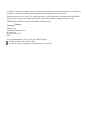
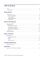


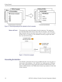
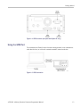


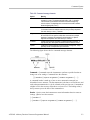


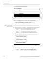

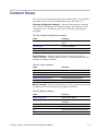


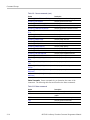
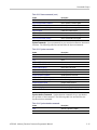


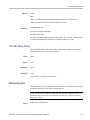


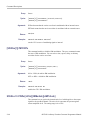
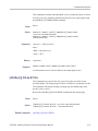
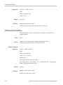
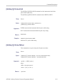


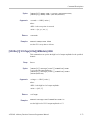
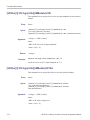

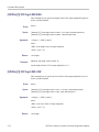
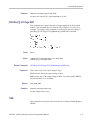


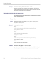
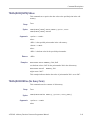
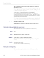

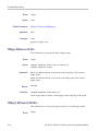


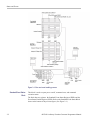

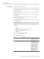
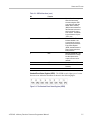
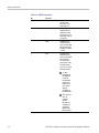


![[SOURce[1|2]]](http://vs1.manualzilla.com/store/data/006001849_1-f604f41c432649719bf8fb1e153f52f2-150x150.png)
![[SOURce[1|2]]](http://vs1.manualzilla.com/store/data/005803287_1-72ff358839cd16ae2e8c94de56269657-150x150.png)