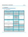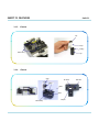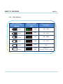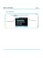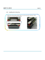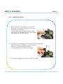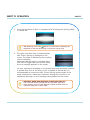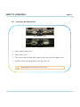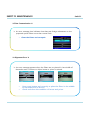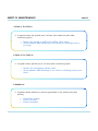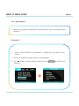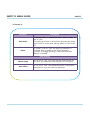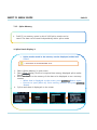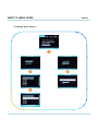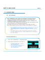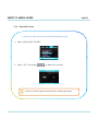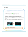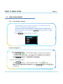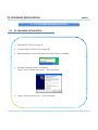
1
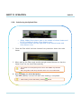
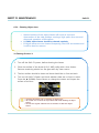
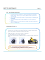
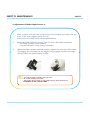
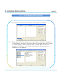
USER MANUAL OPTICAL FIBER FUSION SPLICER SWIFT F1 ¾ Please read entire manual prior to usage. ¾This USER MANUAL must be kept with the SWIFT F1. ILSINTECH CO., LTD. INDEX Swift F1 INDEX 1. 2. SAFETY INFORMATION 1.1. SAFETY INFORMATION 12 1.2. SAFETY MESSAGES 1.3. WARNINGS SPECIFICATIONS & COMPONENTS 2.1. SPECIFICATIONS 2.2. COMPONENTS 2.2.1. STANDARD PACKAGE 2.2.2. OPTION 2.3. 3. RECOMMENDED CONSUMABLE SWIFT F1 FEATURES 3.1. 1 SWIFT F1 BODY 3.1.1. MAIN BODY 3.1.2. AUTO STRIPPER 3.1.3. CLEANER 3.1.4. CLEAVER 315 3.1.5. FUSION SPLICER 3.1.6. SLEEVE HEATER INDEX Swift F1 INDEX 3.2. 3.2.1. FUNCTION BUTTONS 3.2.2. LED INDICATORS 3.3. 4. MONITOR DISPLAY 3.3.1. READY SCREEN 3.3.2. MENU SCREEN SWIFT F1 SETUP 4.1. SETUP 4.1.1. INSTALLING BATTERIES 4.1.2. REMOVING BATTERIES 4.1.3. CHARGING BATTERIES 4.1.4. INSTALLING THE WORK TABLE (CHEST HOLDER) 4.1.5. INSTALLING THE COOLING TRAY 4.1.6. INSTALLING THE HEATER BLOCK R & LEVER BLOCK 4.2. 5. FUNCTION BUTTONS & LED INDICATORS PROGRAM SETUP 4.2.1. FUSION SPLICER MODE 4.2.2. SLEEVE HEATER MODE 4.2.3. AUTO STRIPPER MODE 4.3. ARC CALIBRATION 4.4. INSTALLING THE COOLING TRAY SWIFT F1 OPERATION 5.1. READY SCREEN INDEX Swift F1 INDEX 5.2. 6. OPERATIONS 5.2.1. PREPARING THE FIBER 5.2.3. STRIPPING 5.2.4. CLEANING 5.2.5. CLEAVING 5.2.6. LOADING THE FIBER 5.2.7. FUSION SPLICING 5.2.8. REMOVING THE SPLICED FIBER 5.2.9. REINFORCING THE SPLICED FIBER SWIFT F1 MAINTENANCE 6.1. ERROR MESSAGES 6.2. MAINTENANCE 6.2.1. ARC CALIBRATION 6.2.2. ELECTRODE MAINTENANCE 6.2.3. CLEANING V-GROOVE 6.2.4. CLEANING OBJECTIVE LENS 6.2.5. CLEANING PRISM 626 6.2.6. AUTO STRIPPER MAINTENANCE 6.2.7. CLEAVER MAINTENANCE 6.2.8. SLEEVE HEATER MAINTENANCE 6.2.9. BATTERY MAINTENANCE 6.3. PROBLEM SOLVING 64 6.4. WARRANTY PERIOD & CONTACT NUMBER 6.4.1. WARRANTY PERIOD & LIMIT OF RESPONSIBILITY INDEX Swift F1 INDEX 6.4.2. BEFORE SENDING THE EQUIPMENT 6.4.3. FOR MORE EFFECTIVE MAINTENANCE & REPAIR OF THE EQUIPMENT 7. 6.4.4. Q TRANSPORT OF THE EQUIPMENT 6.4.5. REPAIR SWIFT F1 MENU GUIDE 71 7.1. MAIN MENU 7.1.1. SELECT SPLICE MODE 7.1.2. SELECT HEATER MODE 7.1.3. SELECT STRIPPER MODE 7.1.4. SPLICE OPTION 715 7.1.5. SPLICE MEMORY 7.2. SUB MENU 7.2.1. LANGUAGE 7.2.2. POWER SAVE 7.2.3. MENU LOCK 7.2.4. OTHER OPTION 7.3. AUXILIARY MENU 7.3.1. ARC CALIBRATION 7.3.2. ELECTRODES 7.3.3. CLEAR ARC COUNT 7.3.4. CALENDAR 7.3.5. SENSOR VALUE INDEX Swift F1 INDEX 7.4. 7.4.1. DIAGNOSTIC MENU 7.4.2. DUST CHECK 7.4.3. MOTOR DRIVE 7.4.4. LED CHECK 7.4.5. MAINTENANCE INFO 7.5. 8. OTHER MENU MENU MANAGEMENT 7.5.1. POP-UP MENU SETTING 7.5.2. AUTOMATIC HEATER SETTING 7.5.3. ERROR SETTING or CANCELING PC PROGRAM INSTALLATION 81 8.1. INSTALLATION PROCEDURE SAFETY INFORMATION Swift F1 1 SAFETY INFORMATION 1. This Swift F1 User Manual contains complete Operation & Maintenance instructions. Please review User Manual carefully before operating the Swift F1. 1.1. SAFETY INFORMATION 1.1. Safety Information ¾ Swift F1 has been designed to assure easy and convenient operation in both indoor and outdoor work conditions; however, users need to carefully review this User Manual before operating the Swift F1 in order to prevent any accidents or damage to Swift F1. This easy-and-simple-to-use machine contains potential risks for harm or injury injury. This User Manual provides users with information and tips for safe splicer operation. 1.2 Safety Message Please carefully review User Manual before operating Swift F1. ¾ Ilsintech Co., Ltd. is not liable for any personal injury, physical loss and damage to the Swift F1 caused by inappropriate use or modification of the Swift F1. SAFETY INFORMATION 1.3. Swift F1 Warnings WARNING Please, turn off the power and contact the manufacturer if any of below mentioned incidents occurs while operating the Swift F1. √ √ √ Fumes, Bad Odor, Noise or Overheating occurs Liquid or foreign substances falls into the cabinet ARC fusion splicer is dropped or damaged. Use only the AC power cord provided by the manufacturer. Using an improper AC power cord may cause fire, electric shock or equipment damage resulting in personal injury. Do not touch electrodes when the Swift F1 power is turned on; High voltage and heat generated from the electrodes can cause severe electric shock or burns. Connect AC power cord to the designated electric charger and power outlet outlet. When connecting the AC plug, make sure that there is no dust or foreign matter on the terminal. Incomplete engagement of the cord may cause fumes, electric shock, fire or equipment damage resulting in personal injury or death. SAFETY INFORMATION Swift F1 WARNING Apply correct voltage. The input AC power of the charger is AC 100-240V and 50-60Hz. 50 60Hz. Examine the input AC power before applying because improper frequency or voltage could result in electric shock, equipment breakage, serious injury or death. Excessive electrical current or frequency is often generated by an AC generator. The AC output voltage should be examined by a circuit tester prior to being applied to the equipment. Since improperly high voltage and frequency could cause a serious injury, electric shock, death or damage to the equipment, an examination should be carried out in a regular manner. Do not excessively pull on on, heat or amend the AC power cable cable. The use of damaged power cable may cause fire or injury. Always connect to 3-core AC power cord. Do not use 2-core AC power cord, cable and plug. Do not touch AC plug, AC power cable or ARC fusion splicer with a wet hand. It could result in electric shock. Do not disassemble AC adapter, battery or the unit. Transforming or modification of Swift F1 could cause fire, electric shock or injury. When using an external battery, follow the instructions below; √ Do not discard the battery into a trash incinerator or fire. √ Do not charge or discharge the battery near a flame or blaze. √ Do not excessively shake or physically impact the battery. y is not fully y charged g or g green LED is not turned on in √ If a battery 6 (SIX) hours, immediately stop charging and contact Ilsintech for repair. Do not place any object on the AC adaptor during charging. Use F1-2 charger and F1-B battery pack exclusively designed for the equipment. The use of other battery pack may cause fumes, burn, damage to the unit, injury or death. SAFETY INFORMATION Swift F1 WARNING Use the battery charger (F1-2) which has been designed for the unit. Do not apply different AC power power. Do not make a short circuit of battery (F1-B) or the terminals of the charger. Excessive electrical current may cause personal injury and equipment damage. Do not use Swift F1 splicer in an environment in which flammable liquids or hazardous gas exists. The electric ARC or the ARC fusion splicer may cause fire or explosion. Do not clean Swift F1 with compressed air or compressed gas. Check the condition of belt if there is any damaged or worn out area before transporting the carrier case using the belt. It the carrier case is dropped due to worn out belt, it could damage the unit or people could get hurt. Wear safety goggles always during operating the ARC fusion splicer. If fib fiber fragments f come into i contact with i h the h eye or skin, ki iit could ld b be extremely dangerous. Do not operate the unit in or near a place where temperature is too high. It could result in injury or damage to the equipment. The heat oven reaches high temperatures so extreme caution should be used when operating. p hands and other objects j away y when in use. Please keep Operators are required not to touch the tip of the cleaving blade in order to prevent hand injuries. : Not Touch : Hot : No Freon Gas SAFETY INFORMATION Swift F1 WARNING Do not touch protection sleeve or sleeve heater during heating or immediately after completion of heating. Their surfaces are very hot and touching these may result in burn. Do not place Swift F1 in an unstable place. The unit may fall, causing personal injury or equipment damage. Swift F1 needs to be precisely adjusted and aligned. Do not allow the unit to receive a strong impact. Use supplied carrying case for transportation and storage. The carrying case protects the ARC fusion splicer from damage, moisture shake and shock during storage and transportation moisture, transportation. Maintain the electrodes as instructed below; √ Use only specified electrodes. √ Place new electrodes in the correct position. √ Replace the electrodes as a pair. If a user fails to follow the above instructions, it may cause abnormal ARCdischarge, resulting in equipment damage or degradation in splicing performance. Use pure ethyl alcohol (96% or greater) to clean the objective lens, VGroove, Prism, LCD monitor, Body, etc of the unit. Otherwise blurring, discoloration, damage or performance deterioration may occur. Swift F1 requires no lubrication. The use of oil grease may degrade the splicing performance and damage the equipment. p in a p place where temperature p or Do not store the ARC fusion splicer humidity is extremely high. Equipment failure may occur. The equipment’s technical parts must be examined by a qualified technician or engineer, otherwise, it may cause fire or electric shock. If any problems occur, contact Ilsintech for repair and maintenance.. SPECIFICATIONS & COMPONENTS Swift F1 2 SPECIFICATIONS & COMPONENTS 2. 2.1. SPECIFICATIONS SUBJECT Alignment Clad Diameter Coating Diameter Di Dimension i Weight Average Splice Loss DESCRIPTION Clad to Clad Alignment * Possible to Splice with “Fiber to Connector” & “Fiber to Fiber” * 125㎛ 250 ~ 900㎛ 135(W) 35( ) X 200(L) 00( ) X 82(H)mm 1.5Kg (Body 1.3Kg / Batteries 120gX2) *Mini Mini & Compact size of Swift F1 is able to operate on last terrain, mounted on the chest, on the telephone pole, on the bucket truck, and on the manhole.* (Option: Work Table/Chest Holder) 0.03dB(SM), 0.02dB(MM), 0.06dB(NZDS, DS) Splicing Time Typical 7sec Heating Time Single Fiber: 20sec (26mm), 36sec (40mm) Sleeve Length 26 ~ 40mm Tension Test Splice Memory Compatible Cable Power Battery Capacity No. of Splicing/Heating with Battery 1.96N 2,000 data 0.25mm, 0.9mm, 2.0mm, 3.0mm, Indoor Cable DC Li-Polymer Battery, 100 ~ 240V AC Adapter 1,400mAh X 2 Typical 100 cycles Operation Temp. -10℃ ~ 50℃ Storage Temp. -40℃ ~ 80℃ SPECIFICATIONS & COMPONENTS Swift F1 ※ Auto Stripper ※ SUBJECT DESCRIPTION Applicable Fiber Diameter 125㎛ Applicable Cable Diameter 250㎛, 900㎛ Strip Length Max 28.0mm 28 0mm Heating Time 1 ~ 15 sec Heating Temp. Range 60 ~ 150℃ Tensile Force after Stripping 4kgf ※ Cleaver ※ SUBJECT DESCRIPTION Fiber Diameter 125㎛ Coating Diameter 250 ~ 900㎛ Cleaver Length Single 7.5mm Blade Life Time 48,000 ※ Sleeve Heater ※ SUBJECT DESCRIPTION Applicable Cable Diameter 250㎛, 900㎛, ф2.0mm ~ ф3.0mm Sleeve Length 32mm (Standard) Sleeving Time 20 ~ 35 sec Heat Temp. Range 130 ~ 200℃ SPECIFICATIONS & COMPONENTS Swift F1 2.2. COMPONENTS 2.2.1. Standard Package DESCRIPTION MODEL QUANTITY Clad Alignment Fusion Splicer Swift F1 1 AC Adapter F1-1 1 Battery Charger F1-2 1 Battery Pack F1-B 2 HF-250 (Pair) HF-900 (Pair) Fiber Holder HF-2.5 (Pair) Choice 1 Pair HF-IN (Pair) HF-SC/LC/FC (Ferrule Connector Holder) Spare Electrode EI-19 Heater Cover R Pair 1 #1 – 250~900㎛ (Pair) Lever Block (by Cable & Connector Type on Heater Cover) #2 – 2.4~2.5Ø (Pair) #3 – 3.0Ø (Pair) Choice 1 Pair IN – Indoor (Pair) Wrench 1.5Ø 1 2.0Ø 1 2.5Ø 1 Carrying Case 1 Shoulder Strap 1 CD 1 Brush 1 Brush for V-Groove 1 Tweezers 1 (User Manual, Quick Reference Guide, Product Video) SPECIFICATIONS & COMPONENTS 2.2.1. Swift F1 Option p DESCRIPTION MODEL QUANTITY Working Table (Chest Holder) WK 1 Blade BI-05 1 Cooling Tray CT 1 DC Adapter F1 3 F1-3 1 AC Adapter F1-1 1 Battery charger F1-2 1 Battery Pack F1-B 2 HF-250 Pair HF-900 Pair HF-2.5 Pair HF-IN Pair HF-SC/LC/FC 1 EI-19 Pair Fiber Holder (Ferrule Connector Holder) Spare Electrode Heater Cover R Lever Block (by Cable & Connector Type on Heater Cover) Wrench 1 #1 – 250~900㎛ 250 900㎛ Pair #2 – 2.4~2.5Ø Pair #3 – 3.0Ø Pair IN – Indoor Pair 1.5Ø 1 2.0Ø 1 2.5Ø 1 Carrying Case 1 Shoulder Strap 1 Brush 1 Brush for V-Groove 1 Tweezers 1 SPECIFICATIONS & COMPONENTS 2.3. RECOMMENDED CONSUMABLE ¾ Keep a supply of the following items with the Swift F1 Clad Alignment Fusion Splicer at all times. 9 Denatured Alcohol 9 Lint-Free Tissues 9 Cotton Swab Swift F1 SWIFT F1 FEATURES Swift F1 3 SWIFT F1 FEATURES 3. 3.1. SWIFT F1 BODY 3.1.1. Main Body Auto Stripper Sleeve Heater Cleaver with Fiber Chip Collector Cleaner Wind Cover Splicer Reset / Return Button Power Button LCD Monitor Cursor Buttons Auto Stripper Button (Start Heating) Arc Button (Start Splicing) Enter & Menu Button Sleeve Heater Button (Start Heating) Battery Indicator Button Remaining Battery Indicator LED 3.1.2. Esc Button USB Port Battery y Pack Auto Stripper Blade Slide Cover Slide Base Heater Cover Heater SWIFT F1 FEATURES 3.1.3. Swift F1 Cleaner Cap Pump Sealing Cleaner Ass’y 3.1.4. Cup Cleaver Cover Set Screw Clamp Blade Slider Cleaver Body Damper Rack Gear SWIFT F1 FEATURES 3.1.5. Swift F1 Fusion Splicer Prism Wind Cover Push Block Electrodes V-Groove Holder Base 3.1.6. Sleeve Heater Heater Cover-L Heater Cover-M Heater Heater Cover-R Window SWIFT F1 FEATURES Swift F1 3.2. FUNCTION BUTTONS & LED INDICATORS 3.2.1. Function Buttons Buttons Name Power Left Right Main Functions Turn ON / OFF the Swift F1 Move Left Turning Darker LCD Brightness Move Right Turning Brighter LCD Brightness Up Move Upward Appearing Pop-Up Menu Down Move Downward Appearing Pop-Up Menu Enter Select S l or C Complete l the h S Setting i Appearing Menu Esc Cancel or Edit the Setting Cancel or Initialize the Splicing Reset Auto Stripper ARC Sleeve Heater Cancel or Initialize the Auto Stripper Start or Stop the Auto Stripper Start the Fusion Splicing Start or Stop the Sleeve Heater SWIFT F1 FEATURES 3.2.2. Swift F1 LED Indicators Battery Remaining Battery Capacity Display (Monitor) (5 Bars) (4 Bars) (3 Bars) (2 Bars) (1 Bars) (No Bars) Remaining Capacity Battery Indicator (LED) Remaining Battery Percentage (5 LED) 100 ~ 80% (4 LED) 80 ~ 60% (3 LED) 60 ~ 40% (2 LED) 40 ~ 20% (1 LED) 10% (1 LED or Blinks) Within 5% (Immediate Charge is needed) SWIFT F1 FEATURES Swift F1 3.3. MONITOR DISPLAY 3.3.1. Ready Screen ¾ When the Swift F1 is turned on on, Ready Screen appears after initialized setting. Battery Remaining Current Splice Mode Using ◀▶ (Left/Right) Cursor Button able to change LCD Brightness Current Sleeve Heater Mode ※ In order to setup LCD BRIGHTNESS ※ ¾ Use ◀▶ (Left/Right) Cursor Button to change LCD BRIGHTNESS. Current LCD BRIGHTNESS V Value l •P Pressing i ◀ (Left) (L ft) C Cursor to make DARKER • Pressing ▶ (Right) Cursor to make Brighter Complete the Setting Cancel the Setting SWIFT F1 FEATURES 3.3.2. Swift F1 Menu Screen ¾ Press ENTER button to select Menu Screen. Menu Sections Current Menu Sections SWIFT F1 SETUP Swift F1 4 SWIFT F1 SETUP 4. 4.1. Setup 4.1.1. Installing Batteries & DC Adaptors ¾ The Swift F1 can be powered by two high performance DC Batteries or DC adaptors with an AC adaptor. Work Table (Chest Holder) MT’G AC Battery Button <AC BATTERIES> DC Adaptor <DC ADAPTORS> DC-DC Adaptor ※ Only One Plug-in (Right Side Adapter) ※ Process Introductions ※ ¾ In order to mount Batteries or DC Adaptors, push them up from the bottom of the body until they are seated completely. SWIFT F1 SETUP 4.1.2. Swift F1 Removing Batteries & DC Adaptors ¾ The Swift F1 allows using both high performance AC Batteries and DC Adaptors. Work Table (Chest Holder) MT’G AC Battery Release Button <AC BATTERIES> DC Adaptor Release Button <DC ADAPTORS> ※ Process Introductions ※ ¾ In order to detach Batteries or DC Adaptors, push them toward the front of the body while pressing the release button in the middle. SWIFT F1 SETUP 4.1.3. Swift F1 Charging Batteries ¾ The Swift F1 allows using both high performance AC Batteries and DC Adaptors. Battery Pack AC Adaptor AC Cord F1-2 Charger Battery Remaining LED Indicator ※ Process Introductions ※ 1. Place Battery Packs into the Battery Charger to fit the position of F1-2 connector and connectt AC Ad Adaptor. t 2. Keep charging until LED is Turned Off from RED → GREEN → YELLOW → NO LED. Power Indicator LED LED light turns: Red→Green→Yellow→No LED SWIFT F1 SETUP 4.1.4. Swift F1 Installing the Work Table(Chest Holder) ¾ Swift F1 Work Table is an accessory device, which can be used in combination with the body, to help on-site work such as manhole or telephone pole work. ¾ Connect C the h fi fixing i b bolt l off the h work k table bl to the h ffemale l fi fixing i screw placed l d at the bottom of the Swift F1. Wear the belt over the neck and around the waist while using the equipment. Work Table (Chest Holder) Belts Fixing Bolt SWIFT F1 SETUP 4.1.5. Installing the Cooling Tray ¾ Place the reinforcement sleeve into the cooling tray after heating to allow sleeve to cool down before handling. Swift F1 SWIFT F1 SETUP 4.1.6. Swift F1 Installing the Heater Block R & Lever Block Heater Block R Type Description Type Set Screw Description • LC Connector • 0.25 / 0.9mm Fiber • SC / FC Connector • 2.0 / 2.4mm Cable • 2.0mm Cable • Indoor Cable Lever Block Heater Block L Type Description • 0.25 / 0.9mm Fiber • 2.0 / 2.4mm Cable Heater Block R Type Description • 0.25 / 0.9mm Fiber • LC Connector •2.0 / 2.4mm Cable • 3.0mm Cable • 3.0mm Cable • Indoor Cable • Indoor Cable Standard Package: Heater Block R (2EA), Lever Block (1PAIR) Optional Package: Lever Block (3PAIR) SWIFT F1 SETUP Swift F1 Sleeving 0.9mm Fiber with SC Connector Step 1 2 3 Description • Loosen the Set Screw on Heater Block L • Mount “1” 1 Lever Block • Tighten the Set Screw • Loosen the Screw on Bottom of Heater Block R 4 • Replace the Heater Block R for SC/FC Connector 5 • Placed on the 0.9mm Fiber & SC Connector on the Sleeve Heater 6 • Complete • Tighten the Screw Procedure SWIFT F1 SETUP Swift F1 Sleeving 3.0mm Cable with SC Connector St Step 1 2 3 4 D Description i ti • Loosen the Set Screw on Heater Block L 3 Lever Block • Mount “3” • Tighten the Set Screw • Loosen the Screw on Bottom of Heater Block R • Replace the Heater Block R for SC/FC Connector • Tighten the Screw 5 • Placed on the 3.0mm Cables on the Sleeve Heater 6 • Complete P Procedure d SWIFT F1 SETUP Swift F1 4.2. PROGRAM SETUP 4.2.1. Fusion Splicer Mode ¾ The optimized setting for an accurate optical fiber splice are composed of the following splice elements which rely on the combination of fibers and differences of each fiber. Elements to Elements to Elements to Limit values adjust discharge and heating calculate estimated loss align fibers and adjust splicing process which are used for generating an error message ¾ Th The optimized ti i d elements l t ffor th the b bestt splicing li i result lt h have b been already l d saved d iin the arc fusion splicer. These elements are saved in database from which they can be copied to user program part for use. ※ Selection of Splice Mode ※ 1. Press ENTER Button on the Ready Screen to move Menu When Splice Mode is selected , available splice modes are displayed. 2. Use ▲▼ (UP & DOWN) Cursor Button to move and select a splice mode by pressing ENTER 3 Use ▶ (RIGHT) Cursor Button to move to EDIT MODE 3. MODE. SWIFT F1 SETUP Swift F1 ※ Creating Splice Mode ※ Initially 9 (NINE) Splice Modes are saved in the Swift F1 and other modes are presented as a BLANK. 1. Select a Blank splice mode. 2. Press ▶ (RIGHT) Cursor Button. 3. The types of fibers are displayed. 4. Press ENTER Button to execute. Select Blank Splice Mode ※ Remove Splice Mode ※ A Splice Mode can be removed. 1. Select a splice mode. 2. Press ▶ (RIGHT) Cursor Button to move Edit Mode. 3. Press ▶ (RIGHT) Cursor Button to move yp Edit at “1: Fiber Type”. 4. The types of fibers are displayed. 5. Select Press ENTER Select Blank Splice Mode Button to execute. 9 Mode Number 1 ~ 9 cannot be deleted. 9 Mode Number 1 is automatically selected after completing the removal off a splice li mode. d SWIFT F1 SETUP Swift F1 ※ Editing Splice Mode ※ Splice elements composing each splice mode can be modified. Amount and time of discharge, which are the most important two factors, can be modified by following way. 1. Press ▶ (RIGHT) Cursor Button to move Edit Mode. 2. Use ▲▼ (UP & DOWN) Cursor to change elements. 3. Press ENTER an element. 4. Use ▶◀ (LEFT & RIGHT) Cursor to change the value of the element. 5. Modified value can be saved by pressing ENTER . Button to select SWIFT F1 SETUP 4.2.2. Swift F1 Sleeve Heater Mode ¾ Heater Mode is composed of 12 different modes. The most suitable heater mode needs to be selected before using a protection sleeve. The type of protection sleeve is closely related to the tube heating function. The reference of this mode can be found in database. The user can put a mode into the user’s program after editing and copying or can edit in user program mode. ※ Database ※ PARAMETER DESCRIPTION S-140 T apply To l h heat to standard d d 40 40mm Sl Sleeve (ILSINTECH S-140). 28mm To apply heat to standard 28mm Sleeve. SWIFT F1 SETUP ※ Heater Mode Selection ※ Selects the most appropriate heater mode of the fiber protection sleeve in use. 1. “Heater Mode Selection” Menu is displayed when “Heater Mode Selection” is selected in Main Menu. 2. Select a Heater Mode using ▲▼ (UP & DOWN) Cursors and press ENTER to set set. ※ Heater Mode Modification ※ The Sleeve Heater settings saved in Heater Mode can be changed. 1. Select Edit Mode in “Heater Mode Selection” Mode using the Cursor. “Heater Mode Edit” is displayed when ▶ (RIGHT) Cursor is pressed. 2. ▲▼ (UP & DOWN) Cursor to set of a parameter to change and press ENTER . 3. Move to the mode to use ◀▶ (LEFT & RIGHT) and press ENTER . Swift F1 SWIFT F1 SETUP Swift F1 4.2.3. Auto Stripper Mode There are 2 (TWO) Stripper Modes, STRIP TEMP & STRIP HEAT. Since the types of fibers vary, the most suitable Stripper Mode should be selected. ※ Heater Mode Modification ※ 1. “Stripper Mode” is selected in “Main Menu” to display Stripper Mode. 2. When ENTER temperature. is selected, temperature setting bar shows current set SWIFT F1 SETUP Swift F1 ※ Selection of Strip Time ※ 1. Select “Strip time Selection” to display Strip Time. 2. When 3. Select appropriate Strip Time by using ◀▶ (LEFT & RIGHT) Cursor and Confirm the adjustment by pressing ENTER . ENTER is pressed, time setting bar shows the current set time. 9 Strip Time can be set from 0 to 15 seconds. 9 Select a time frame suitable for the sheath of the fiber to be used. SWIFT F1 SETUP Swift F1 4.3. ARC CALIBRATION ¾ ARC CALIBRATION current needs to be calibrated in accordance with the changes in temperature, humidity and air pressure of surrounding area. e pe atu e, humidity u d ty a and da air p pressure essu e se sensors so s a are e use useful u in ca calibrating b at g ARC C ¾ Temperature, CALIBRATION depending on external conditions. ¾ The changes of ARC POWER current caused by the wear of electrodes and fiber splicing operation are not calibrated automatically. ¾ In addition, the central axis could be moved to either right or left side. ¾ Such case will affect the splice position of fiber, hence calibration is required. ARC CALIBRATION should be performed everyday prior to initial use of the Swift F1 F1, or when high splice losses are observed observed. “ARC CALIBRATION” is a function to adjust the current “ELEMENT” value. The element value is used in the operation program for splicing. The ARC CALIBRATION value of ARC POWER cannot be changed in the “Splice Mode”. ※ Process Introduction ※ 1. Select “ARC CALIBRATION” in “AUXILIARY MENU”. 2. Place cleaved optical fiber in the Swift F1. In general “SM” fiber is used for ARC CALIBRATION. Use a clean fiber because Dust on the fiber surface may affect ARC CALIBRATION SWIFT F1 SETUP Swift F1 ※ Process Introduction ※ 3. Press 4. ENTER Button. ARC is carried out after aligning the fiber. j according g to ARC Condition. The ARC POWER is adjusted The initial cleave angle is not related to the parameter, “Cleave Loss”. It can be independently set for ARC Capacity Adjustment. When measuring is done, the following result is displayed on the Screen. g ※ ※ Result Messages “Calibration Complete” Message ¾ This message means that ARC CALIBRATION & setting splice position have been successfully completed. Press ESC to close the function. “Test Again” Message ¾ This message means ARC CLIBRATION needs to be carried out again because huge difference occurs after calibration. Prepare a new fiber, close wind cover and press ENTER Button . E Even if the th calibration lib ti iis nott completed, l t d it could ld be cancelled by pressing ESC button. In some cases, many times of RE-ARC CALIBRATION are required to get a successful result or “Calibration Complete” message. If no such message is displayed even after a series of RE-ARC CALIBRATION, it can be considered that a successful result has been achieved. SWIFT F1 OPERATION Swift F1 5 SWIFT F1 OPERATION 5. 5.1. READY SCREEN ¾ When the Swift F1 turned on, Ready Screen appears after initialized setting. 5.2. OPERATION Before starting the fusion splicing operation, please perform: 1. ARC CALIBRATION 2. Correct Splice, Stripper and Heater Mode Program Selection 5.2.1. Preparing the Fiber ¾ Insert the optical fiber into the protection sleeve tube. Sleeve Tube Optical Fiber SWIFT F1 OPERATION 5.2.2. Swift F1 Stripping Procedure 1. Press the auto stripper power button to begin the stripping process. p thermal stripper pp cover and slide cover for p preparation. p Open 2. Place fiber into the holder as shown in pictures below. The minimum stripping length should be longer than 18mm. 250㎛ Type 3. 900㎛ Type ф2.0 ~ 3.0 Jumper Cord Type Connector Type Mount the holder containing the fiber onto the slider and close slide cover. 250㎛ Type 900㎛ Type ф2.0 ~ 3.0 Jumper Cord Type SWIFT F1 OPERATION 4. Once the thermal stripper cover is closed, the fiber is heated up for a predefined time and the coating is stripped by moving the slider. 250㎛ Type 5. Swift F1 900㎛ Type Connector Type When stripping is completed, open the slide cover and detach the holder containing the stripped fiber. The slider part moves to the initial position as thermal stripper cover is opened. 6. Remove anyy remaining g coating g residue form stripper pp heater and blade areas using a soft brush before next operation. Be careful in handling blade part which is very sensitive. SWIFT F1 OPERATION 5.2.3. 1. Cleaning Procedure When Cleaning, press down on the alcohol dispenser 2 or 3 times, using Lint-Free Tissue as shown in the picture. To avoid splashing the alcohol please cover the top part of dispenser with Lint-Free Tissue while dispenser is being pressed. 2. If no alcohol is discharged, open cap and refill the dispenser. Add alcohol after completely removing it from the Swift F1 body by pulling upward upward. It is connected to the Swift F1 by magnet. 3. The recommended cleaning fluid is MCC-POC03M. Swift F1 SWIFT F1 OPERATION 5.2.4. Swift F1 Cleaving Procedure 1. Open p cover and set the holder containing g stripped pp fiber into the cleaving g position. Check Whether the fiber is lying in place. Use the Chip-Box located at the right side of the Swift F1. 250㎛ Type 900㎛ Type Connector Type 2. Press the cover to cleave the fiber. 250㎛ Type 900㎛ Type Connector Type SWIFT F1 OPERATION 3. Open the cover and check the result. 250㎛ Type 4. Swift F1 Connector Type Take out the cut fiber and holder. Be careful not to contaminate the fiber with dust or foreign substance. The fiber shards are collected in the slide-type Chip Box placed at the side of Swift F1 body. SWIFT F1 OPERATION 5.2.5. Swift F1 Loading the Fiber 1. Open p wind cover. 2. Place the holder containing the fiber which has been stripped, cleaned and cleaved onto the holder base in right direction. Splice with Fiber to Fiber p with Fiber to Connector Splice 9 Be careful that the tip of the prepared fiber is not to be damaged by contacting other objects. 3 Carefully 3. C f ll close l th the wind i d cover. 4. Start splicing by pressing verified on the monitor. Button when the alignment of the fiber is SWIFT F1 OPERATION 5.2.6. Fusion Splicing The condition of the fiber can be observed through the image processing system of Swift F1. y test is required q to ensure a better splicing p g However, a naked eye result. 1. The fibers placed into the Swift F1 gradually move toward each other. The fibers which has been moving gradually stop at a position where splicing can be carried out accurately. Then, it checks the cleave angle, the cross section condition of optical fiber and the existence of foreign substance. An error message is presented on the screen if the measured cleave angle is bigger than pre-defined limit value or broken part is discovered. At the same time, the splicing process is stopped. If such error message does not appear on the screen, check the condition of cross section through a naked eye inspection. Refer to below illustration. If one of below conditions is observed, remove the fiber from the Swift F1 and place a new optical fiber. These conditions will cause a bad splicing result. 2. The fibers of which inspection has been completed are arranged clad to clad. Measured clad values can be displaced on the screen. 9 The limit value of optical fiber cleave angle can be adjusted. 9 If user wants to proceed to next stage, press Button despite the error message about cleave angle. 9 The cleave angle, clad axis deviation can be hidden on the screen during ARC Fusion Splicing. Swift F1 SWIFT F1 OPERATION 3. Once the alignment of fiber is completed, ARC Discharge for splicing fibers is carried out. 9 ARC Discharge starts when Button is pressed after completing the alignment in case that the splicing is carried out step by step. 4. The splice loss value that is measured after ARC Fusion Splicing is displayed on the screen. The value is affected by the condition of error elements. Measured cleaved angle or calculate splice loss value is bigger than pre-set limit value, an error message appears on the screen. An error message is displayed on the screen when and abnormal condition in spliced fiber such as too thick or thin or bubble is discovered. It is recommended to conduct the ARC Fusion Splicing process again if the result observed by a naked eye inspection through the monitor is not satisfactory although no error message has appeared on the screen. 9 Sometimes Sometimes, spliced point looks fatter or bigger than other part part. This is normal result of splicing and does not affect splice loss. 9 Refer to Menu section of User Manual to adjust the limit values of measured splice loss or cleave angle. Swift F1 SWIFT F1 OPERATION Sometimes, splice loss could be enhanced by conducting additional ARC Discharge. Press Button to carry out additional ARC Discharge. Calculating splice loss and checking splice result are carried out again. 9O Occasionally, i ll th the result lt off additional dditi l ARC Di Discharge h could ld worsen splice li loss. Additional ARC Discharge can be set to OFF or the maximum number of additional ARC Discharge can be set. 9 It is crucial to maintain V-Groove in a clean condition prior to conducting splicing operation. Swift F1 SWIFT F1 OPERATION 5.2.7. Swift F1 Removing the Spliced Fiber Splice with Fiber to Fiber Splice with Fiber to Connector 1. Open sleeve heater cover. 2. Open wind cover. 3. Take out the spliced fiber after opening right and left side holder cover. 4. Carefully move the sleeve tube to the splicing part. 9 Hold the fiber until moving it to tube heater. SWIFT F1 OPERATION 5.2.8. Reinforcing the Spliced Fiber 1. Swift F1 250㎛, 900㎛: Place sleeve tube in the middle of sleeve heater and fix it by pushing it down. Close heater cover. Connector: Insert into the right side of the sleeve heater and close heater cover. Place the fiber which has been inserted into protection sleeve into tube heater. 2. When placing the fiber, apply tensile strength toward bottom so that the heater cover can be closed automatically. 9 It is crucial to set the splice point to be in the middle of protection sleeve. 9 Place the guide inside the protection sleeve to be set underneath. 3 P 3. Press B Button tt tto start t t ttube b h heating. ti Heat LED (GREEN) is turned off when tube heating is completed. 9 Tube heating can be aborted by pressing Button. SWIFT F1 OPERATION 4. Swift F1 Take out the protected fiber from the heater after opening the heater cover. 9 Protection sleeve could be stuck to the bottom of the heater. Use a cotton swab to separate the sleeve form the heater. 5. Always examine the final sleeve to check whether there are bubbles, residue or dust in the sleeve. 250㎛ Type 900㎛ Type Connector Type Cooling Tray Connector Type 900㎛ Type 250㎛ Type SWIFT F1 MAINTENANCE Swift F1 6 SWIFT F1 MAINTENANCE 6. 6.1. ERROR MESSAGES Symptom Clad Deviation Clad Angle Clad Deformation Clad Flexion Burning Refer to the following table for trouble shooting when Error Messages have appeared. Cause Solution Dust in V-Groove or the chip of core wire guide. Cleaning V-Groove or the chip of core wire guide. Dust in V-Groove or the chip of core wire guide. Cleaning V-Groove or the chip of core wire guide. Bad condition of the cross section of fiber. Checking whether fiber cleaver is working properly. Bad condition of the cross section of fiber. Checking whether fiber cleaver is working properly. Too low amount or short time of initial arc discharge Increasing the amount and time of initial arc discharge. Bad condition of the cross section of fiber. Checking whether fiber cleaver is working properly. Too low amount or short time of initial arc discharge. Increase the amount and time of initial arc discharge. Bad condition of the cross section of fb fiber. Checking whether fiber cleaver is working k properly. l Dust still remaining after cleaning the fiber or conducting cleaning discharge. Cleaning carefully the fiber or increasing the arc discharge time. Symptom Cause Solution Bubble Bad condition of the cross section of fiber. Checking whether fiber cleaver is working properly. Too low amount or short time of initial arc discharge. Increase the amount and/or time of initial are discharge. Increase overlapping. Separation Thi k Thick Thin Line Too high amount or long time of initial arc discharge. Decreasing the amount and/or time of initial arc discharge. Too long fiber length. Reducing the length of duplicated area. Improper discharge amount. Conducting discharge amount calibration A few improper discharge factors. Adjusting initial discharge amount, initial discharge time and overlapped area. Several number of improper discharge factors. Adjusting initial discharge amount, initial discharge time and overlapped area. 9When splicing MM fibers or fibers with different diameters, sometimes, “Vertical Lines” appear on splicing point 9“Vertical Lines” does not affect splice loss or splice quality including t tensile il strength t th SWIFT F1 MAINTENANCE Swift F1 6.2. MAINTENANCE 6.2.1. ARC Calibration ¾ Perform the ARC Calibration: 1. Before Operating Fusion Splicer. 2. When High Splice Losses are observed. 6.2.2. Electrode Maintenance ¾ As the Splice is used, the electrode is worn out and Silica Oxidized substances are accumulated. Therefore, regular cleaning is needed. It is recommended to replace the Electrodes after approximately 2,000 arcs. When the discharge count exceeds 2,000 times, a message to request for the replacement of electrodes appears. If this happens, turn off the Swift F1 and replace the electrodes. Not doing so may result in high splice loss and deterioration of the splice point point. SWIFT F1 MAINTENANCE ※ Replacement Process ※ Select AUX Menu, press ENTER “ELECTRODES”. Press ENTER “REPLACE ELECTRODES” There is the Replace Electrodes Procedure Information 1. Turn off the Swift F1. 2. Loosen the Thumb-Screws and remove the electrodes. 3. Clean carefully new electrodes with a cotton swab wet in alcohol and mount them to the Swift F1. 4. Turn on the Swift F1 and perform “ARC CALIBRATION” and “STABILIZE ELECTRODES” at least 1 (ONE) time from AUX MENU. 5 Set the 0 (ZERO) ARC Count through the “CLEAR 5. CLEAR ARC COUNT” COUNT from AUX MENU. 9 Turn Off the Swift F1 before the procedure. 9 Be careful handling the ELECTRODES. Swift F1 SWIFT F1 MAINTENANCE Swift F1 6.2.3. Cleaning V-Groove Contaminants in V-Grooves may cause improper fiber alignment, resulting in high splice loss. V-Grooves must be frequently inspected and regularly cleaned even during normal daily operation. ※ Cleaning Process ※ 1. Open Wind Cover. 2. Clean the bottom of V-Groove with Brush for V-Groove or a Cotton Swab wet in alcohol. Remove remaining alcohol with a clean dry cotton swab. 3. If contaminants in V-Grooves are not fullyy removed with a cotton swab moistened with alcohol, use the ends of cleaved optical fibers to remove them. 4. Repeat Step 2. 9 Turn Off the Swift F1 before the Cleaning procedure. 9 Please be careful not to touch the electrodes. 9 Do not apply too much force when cleaning. It may cause damage to the V-Groove 9 Brush the V-Groove frequently q y before / after using g Swift F1. SWIFT F1 MAINTENANCE Swift F1 6.2.4. Cleaning Object Lens Stained surface of the object lenses will result in incorrect observation of the clad position causing a high splice loss rate and abnormal operation of the splicer. 2 (TWO) object lenses should be cleaned regularly regularly. If object lenses are not cleaned frequently, dust will accumulate and it will be hard to remove. ※ Cleaning Process ※ 1. Turn off the Swift F1 power, before cleaning the lenses. 2. Clean the surface of the lenses (X & Y AXIS) softly with a lens cleaner. Remove remaining alcohol on the glass with dry clean cotton. 3. The lens surface should be clean and there should be no line and stain. 4. Turn on the Swift F1 Power and check whether there are no lines or stains. Press the ▼ (DOWN) Cursor Button to change the screen and inspect the surface of the lens. 9 Remove electrodes prior to cleaning an object lens. 9 Be careful not to touch the tip of electrode while cleaning an object lenses. 9 Do not use organic solvents such as acetone to clean the object lenses. SWIFT F1 MAINTENANCE 6.2.5. Cleaning Prism If stains cannot be removed from the surface of the Prism by cleaning, the prism needs to be replaced. ※ Cleaning Process ※ 1. Turn Off the Swift F1 Power. 2. Open wind cover. 3. Clean the surface of the prisms with a lens cleaner or cotton swab. 9 Separate electrodes prior to cleaning an object lens. 9 Be careful not to touch the tip of electrode while cleaning an object lenses. 9 Do not use organic solvents such as acetone to clean the object lenses. Swift F1 SWIFT F1 MAINTENANCE Swift F1 6.2.6. Auto Stripper Maintenance Be careful of using, handling or storing principal parts including blades, heater, etc as they are closely related to the equipment’s operation life. Do not apply unnecessary weight or physical impact in handling the equipment. Keep the principal parts of the equipment in a clean condition always. Keep it clean and in a case when not using, which will increase the life of the equipment. ※ Maintenance Process ※ 1. Remove worn out blade by unscrewing fixing bolts as shown below picture. At this time, move the slide part to the left hand side. 2 2. Place new blades in the reverse manner of removing removing. (2 (TWO) blades as a pair at top and bottom) Make sure that both blades fit tightly in place in order to achieve a good strip result. < Cleaning Auto Stripper > 9 Turn Off the Swift F1 before Cleaning & Inspection. 9 Brush the Auto Stripper frequently before & after using the Swift F1. Be careful handling Stripper Blade Part which is very sensitive. 9Be SWIFT F1 MAINTENANCE Swift F1 6.2.7. Cleaver Maintenance 1 to 16 channel (Cleaver Positions) is marked on a blade. If cleaver is not cleaving properly, clean the top and bottom rubber pads and the edge of the blade with a cotton swab wet in alcohol. ※ Do not use ACETONE or SOLVENT in cleaning the rubber pads. ※ If th the lif life off th the bl blade d iis almost l t over, th the fib fiber will ill nott cleave l att all. ll Change the blade channel or replace with new one. ※ Changing Blade Channel (Cleave Position) Process ※ 1. Detach the automatic cleaver from the Swift F1 Main Body using a Hexagon Wrench. 2. Open the cover and push the slider forward. When the slider is fixed, loosen the set screw slightly (about 2 turns) with a Hexagon Wrench. 3. Turn the marking on the blade counter clock wise one by one with a cotton swab. Assemble the automatic cleaver in the reverse manner of detaching. 9 Turn Off the Swift F1 before doing process. 9 Be careful handling the blade. SWIFT F1 MAINTENANCE Swift F1 ※ Blade Replacement Process ※ 1. Loosen the set screw at the side of the cleaver detached from the body slightly (around 2 turns) with a wrench. 2. Insert a wrench into the hole at the bottom of the cleaver and loosen the set screw of the slider slightly (about 2 turns). At this point, the slider has to be moved backward. 3. Insert the wrench bolt into the cam pin and pull it with tweezers and detach the slider. 4. Be careful not to damage the blade. Assemble the part in the verse manner. Tighten the set-screw firmly. 9 Turn Off the Swift F1 before doing process. 9 Be careful handling the blade. 9 Thoroughly & Accurately set the height using a gauge because the h i h di height directly l effects ff S SPLICE C LOSS. OSS SWIFT F1 MAINTENANCE Swift F1 ※ Adjustment of Blade Height Process ※ 1. Insert a wrench into the hole at the bottom of the cleaver and loosen the set screw of the slider slightly (about 2 turns). At this point, the slider has to be moved backward. 2. Adjust the blade height by turning Cam Pin with a flat-head screwdriver. Clockwise Turning: Going Upward Counterclockwise Turning: Going Downward 3. When the blade reaches required position, tighten the set-screw of the slider. g y and accuratelyy set the height g using gag gauge g because the height g Thoroughly directly effects the cleave quality of fiber. 9 Turn Off the Swift F1 before doing process. 9 Be careful handling the blade. 9 Thoroughly & Accurately set the height using a gauge because the h i h di height directly l effects ff S SPLICE C LOSS. OSS SWIFT F1 MAINTENANCE Swift F1 6.2.8. Sleeve Heater Maintenance Be careful in using, handling or storing principal parts including blades, heater, etc as they are closely related to the life of the equipment. Do not apply unnecessary weight or physical impact in handling the equipment. Keep the principal parts of the equipment in a clean condition always. Keep it clean and in a case when not using, which will increase the life of the equipment. ※ Adjustment & Replacement of Sleeve Heater Block Process ※ 1. Loosen the bolt as shown in below p picture and replace p sleeve heater block with new one. 250 / 900㎛ Type Connector Type SWIFT F1 MAINTENANCE 6.2.9. Battery Maintenance Discharge the battery completely at least once every 3 (THREE) months in order to avoid memory effect. S Storage temperature should h ld b be b between -20℃ 20℃ and d 30℃ 30℃. Recharge the battery every 6 (SIX) months when not in use. Swift F1 SWIFT F1 MAINTENANCE Swift F1 6.3. PROBLEM SOLVING After splicing, if loss rate is too big or any abnormal results are discovered, follow instructions below; ※ Fiber Contamination ※ 1. It could be caused by dust or foreign substances on the surface of fiber. y clean the surface of fiber. Sufficiently Do not clean the fiber after cutting to prevent the cross section being stained. Do not slide the fiber into V-Groove. Set the fiber at the V-Groove by placing it vertically. 2. Foreign substances in V-Groove will hinder a correct alignment. Maintain V-Groove V Groove and fiber holder in a clean condition at all times. 3. Bad electrode condition. An electrode has to be replaced if it is worn off or its tip is bent or contaminated. 4. Improper ARC-discharge current or discharge time. Check the discharge current and time and set it again to a proper value. Initial setting value are the most optimized settings. 5. Incorrect splice mode Check whether a proper splice mode for a specific fiber type has b been selected. l t d SWIFT F1 MAINTENANCE ※ Abnormal Splicing Operation ※ 1. Alignment operation is continued. Open wind cover and close it again. Open wind cover to generate an error. Press reset button and turn off the power. Contact ILSINTECH. 2. “Optical Fiber is Too Long” error occurs continuously. Reset and turn off the power. Contact ILSINTECH. Swift F1 SWIFT F1 MAINTENANCE ※ Fiber Contamination ※ ¾ An error message that indicates that there are foreign substances on the prepared optical fibers more than normal limit. Clean the fibers and set again ※ Alignment Error ※ ¾ A An error message appears when h th the fib fibers are nott placed l d iin th the middle iddl off electrodes and V-Groove or object lenses or prism is stained. Press reset button and correctly re-place the fibers in the middle of electrodes and V-Groove. Check and clean the condition of lenses and prism. Swift F1 SWIFT F1 MAINTENANCE ※ Optical Fiber is Too Long ※ ¾ It appears when fibers are placed too close to electrodes or LED light is not bright enough due to stains on the lenses or prism. Press reset button and correctly re-place th fib the fibers. Clean the condition of lenses and prism. Conduct LED examination, if there is an error, Contact ILSINTECH. ※ Cleave Angle is Too Big ※ ¾ It appears when the measured value of fiber cleave angle is bigger than angle limit. Check the condition of fiber cleaver and reset the fiber. Check the limit of cleave angle. ※ Cleave Angle is Too Big ※ ¾ It appears when the estimated loss value is bigger than loss limit. Check the loss limit setting. Swift F1 SWIFT F1 MAINTENANCE Swift F1 ※ Fiber is Too Thin ※ ¾ It appears when the spliced part is thinner than reference value after conducting splice. R d Reduce the h llength h to pull ll iin the h pulling lli splice li menu. Check whether ARC-Discharge is too strong or discharge time is too long. ※ Fiber is Too Thick ※ ¾ It appears when spliced part is too thick after conducting splice. Reduce the overlapping setting value. Check whether ARC-Discharge is too weak or discharge time is too short. ※ Bubbles ※ ¾ It appears when bubbles or dots are generated on the spliced part after splicing. Check fiber cleaver. Clean V-Groove. Check electrodes. SWIFT F1 MAINTENANCE Swift F1 6.4. Warranty Period & Contact 6.4.1. Warranty Period & Limit of Responsibility ¾ If the h Swift S if F1 iis b broken k within i hi 1 (ONE) year ffrom d delivery, li iit will ill b be repaired i d by the manufacturer for free. However, the buyer will be charged for the repair regardless of the warranty period if the breakage or damage incurred due to: 1. 2. 3. 4. Natural disaster Application of abnormal high frequency voltage. Negligent handling. Handling or maintenance not meeting the operational procedures or instructions presented in service manual and 5. Breakage of or damage to consumables such as electrodes, etc. 6.4.2. Before Sending the Equipment ¾ Please Contact ILSINTECH 6.4.3. For More Effective Maintenance and Repair of the Equipment 1. Please send the Swift F1 with a note on it. The note should include the following information. (Name, Department, Address, Telephone Number, FAX Number, E-mail Address) 2. The Swift F1 Serial Number. 3. The state of the splicer, the current time and error message contents concerning the monitor. SWIFT F1 MAINTENANCE 6.4.4. Transport of the Equipment ¾ Since the Swift F1 is high-precision equipment, it is required to protect it from moisture, shaking or physical impact by transporting it in the carrying case. When requesting for repair service service, please please, make sure that the body with components is sent in the carrying case. 6.4.5. Repair ¾ Data saved in memory such as splice result could be erased during the repairing process. Swift F1 SWIFT F1 MENU GUIDE Swift F1 7 SWIFT F1 MENU GUIDE 7. 7.1. MAIN MENU 7.1.1. Select Splice Mode ¾ The optimized setting for an accurate optical fiber splicing are composed of following splice elements which rely on the combination of fibers and differences of each fiber. Elements to Elements to Elements to Limit values adjust discharge and heating. calculate estimated loss. align fibers and adjust splicing process. which are used for generating an error message. ¾ The optimized elements for the best splicing result have been already saved in the arc fusion splicer. These elements are saved in database from which they can be copied to user program part for use ※ Selection of Splice Mode ※ 1. Press ENTER Button on the Ready Screen to move Menu. When Splice Mode is selected , available splice modes are displayed. 2. Use ▲▼ (UP & DOWN) Cursor Button to move and select a splice mode by press ENTER . 3 Use ▶ (RIGHT) C 3. Cursor so B Button tton to mo move e EDIT MODE MODE. SWIFT F1 MENU GUIDE Swift F1 ※ Creating Splice Mode ※ Initially 9 (NINE) Splice Modes are saved in the Swift F1 and other modes are presented as a BLANK. 1. Select a Blank splice mode. 2. Press ▶ (RIGHT) Cursor Button. 3. The types of fibers are displayed. 4. Press ENTER Button to execute. Select Blank Splice Mode ※ Remove Splice Mode ※ A Splice Mode can be removed. 1. Select a splice mode. 2. Press ▶ (RIGHT) Cursor Button to move Edit Mode. 3. Press ▶ (RIGHT) Cursor Button to move yp Edit at “1: Fiber Type”. 4. The types of fibers are displayed. 5. Select Press ENTER Select Blank Splice Mode Button to execute. 9 Mode Number 1 ~ 9 cannot be deleted. 9 Mode Number 1 is automatically selected after completing the removal off a splice li mode. d SWIFT F1 MENU GUIDE ※ Editing Splice Mode ※ Splice elements composing each splice mode can be modified. Amount and time of discharge, which are the most important two factors, can be modified by following way. 1. Press ▶ (RIGHT) Cursor Button to move Edit Mode. 2. Use ▲▼ (UP & DOWN) Cursor to change elements. 3. Press ENTER an element. 4. Use ▶◀ (LEFT & RIGHT) Cursor to change the value of the element. 5. Modified value can be saved by pressing ENTER Button to select Swift F1 SWIFT F1 MENU GUIDE 7.1.2. Swift F1 Sleeve Heater Mode ¾ Heater Mode is composed of 12 different modes. The most suitable heater mode needs to be selected before using a protection sleeve. The type of protection sleeve is closely related to the tube heating function. The reference of this mode can be found in database. The user can put a mode into the user’s program after editing and copying or can edit in user program mode. ※ Database ※ PARAMETER DESCRIPTION S-140 T apply To l h heat to standard d d 40 40mm Sl Sleeve (ILSINTECH S-140). 28mm To apply heat to standard 28mm Sleeve. SWIFT F1 MENU GUIDE ※ Heater Mode Selection ※ Selects the most appropriate heater mode of the fiber protection sleeve in use. 1. “Heater Mode Selection” Menu is displayed when “Heater Mode Selection” is selected in Main Menu. 2. Select a Heater Mode using ▲▼ (UP & DOWN) Cursors and press ENTER to set set. ※ Heater Mode Modification ※ The Sleeve Heater settings saved in Heater Mode can be changed. 1. Select Edit Mode in “Heater Mode Selection” Mode using the Cursor. “Heater Mode Edit” is displayed when ▶ (RIGHT) Cursor is pressed. 2. ▲▼ (UP & DOWN) Cursor to set of a parameter to change and press ENTER . 3. Move to the mode to use ◀▶ (LEFT & RIGHT) and press ENTER . Swift F1 SWIFT F1 MENU GUIDE Swift F1 7.1.3. Auto Stripper Mode There are 2 (TWO) Stripper Modes, STRIP TEMP & STRIP HEAT. Since the types of fibers varied, select the most suitable Stripper Mode should Be selected. ※ Heater Mode Modification ※ 1. Select “Stripper Mode” is selected in “Main Menu” to display Stripper Mode. 2. When ENTER temperature. is selected, temperature setting bar show current set SWIFT F1 MENU GUIDE ※ Selection of Strip Time ※ 1. Select “Strip time Selection” to display Strip Time. 2. When 3. Select appropriate Strip Time by using ◀▶ (LEFT & RIGHT) Cursor and Confirm the adjustment by pressing ENTER . ENTER is pressed, time setting bar shows the current set time. 9 Strip Time can be set from 0 to 15 seconds. 9 Select a time frame suitable for the sheath of the fiber to be used. Swift F1 SWIFT F1 MENU GUIDE Swift F1 7.1.4. Splice Option Allows setting general parameters of every mode for splicing and tube heater operation. ¾ ※ Process ※ 1. Select “SPLICE OPTION” in “Main Menu” to display menu list splice on the screen. 2. Users are allowed changing some of the parameters. 3. Use ◀▶ Button to select required value and press selection. ENTER to confirm the SWIFT F1 MENU GUIDE Swift F1 ※ Process ※ Parameter Description Auto Start Automatic splice is carried out when “AUTO AUTO START” START is set to “ON”. The splicing process is carried out automatically when wind cover is closed after placing fibers into the Swift F1. Pause If “Pause” is set to “ON”, the splicing operation is stopped after completing the fibers alignment. The ARC-Discharge ARC Discharge splicing is resumed when ARC Button is pressed. Data Display Cleave Angle If it is set to “ON”, the right and left cleave angle of the fiber are measured and displayed on the screen. Axis Offset If it is set to “ON”, the measured values of alignment deviation of core and clad are displayed SWIFT F1 MENU GUIDE Swift F1 7.1.5. Splice Memory ¾ Swift F1 has memory space in which 2,000 splice results can be saved. The data can be saved independently within splice mode. ※ Splice Result Display ※ Splice results saved in the memory can be displayed displayed, added and edited. 9 Saved data can be downloaded to PC. 1. Select [Splice Memory] in main menu. 2. Select 2 S l t [D [Date t Di Display]. l ] A And d fi find d a required i d it item among di displayed l d splice li results. lt Press ENTER . 3. Move the Cursor to the memory of the data to be displayed to set a memory number. When data is displayed on the screen, press ENTER Button again. Press ▶ to open [Move to]. Set a memory number and press ENTER Button. 4. Splice result data is displayed on the screen. SWIFT F1 MENU GUIDE Swift F1 ※ Deleting Splice Result ※ A part of or an entire splice result saved in the memory can be deleted. 1. Select [Clear Memory] in [Splice Memory] to display menu for deleting splice result. Clearing Entire Splice Result 2 Move to [Clear All Data] and press 2. Yes or No selection appears. 3. If ENTER ENTER . Button Button. Button is pressed one more time, entire splice results are removed. Clearing a part of Splice Result 2. Select [Clear Part Memory] and press Memory] menu. ENTER Button to move to [Clear Part 3. Set the range of data (from the start number to the last number to be removed) using ▲▼◀▶ Cursor Buttons and press ENTER Button to delete Those selected ones. The empty space after clearing is filled with the first data coming after the last data deleted. SWIFT F1 MENU GUIDE ※ Deleting Splice Result ※ Swift F1 SWIFT F1 MENU GUIDE Swift F1 7.2. SUB MENU This menu is composed of a set of SUB MENU, each of which controls detailed function of the equipment equipment. 1. Press ENTER Button and Cursor Buttons to move SUB MENU. 2. Each setting can be selected and modified. 7.2.1. Language 1. Select Language in SUB MENU and press 2. Select required language format and press ENTER. ENTER . . SWIFT F1 MENU GUIDE 7.2. SUB MENU 7.2.2. Power Save Power saving function is essential for energy preservation. It is recommended to set power saving function to increase the number of splices carried out by the battery packs. 1. Insert power supply unit into the equipment and turn on the power. 2 Select Power Save in the menu 2. menu. 3. Select power saving option for both monitor and ARC Fusion Splicer. Swift F1 SWIFT F1 MENU GUIDE Swift F1 Power saving function is essential for energy preservation. It is recommended to set power saving function to increase the number of splices carried out by the battery packs. 1 Insert power supply 1. l unit i iinto the h equipment i and d turn on the h power. 2. Select Power Save in the menu. 3. Select power saving option for both monitor and ARC Fusion Splicer. OPTION DESCRIPTION Monitor Shut Down The power of LCD monitor is cut off if the equipment is not activated for a certain period of time. It is very important to activate this function when using battery packs. When the monitor is turned off, press ENTER Button to turn on the screen. Splicer Shut Down The Swift F1 p power is cut off if the Swift F1 is not activated for a certain period of time. SWIFT F1 MENU GUIDE Swift F1 7 2 3 Menu Lock 7.2.3. 1. Select MENU LOCK in [SUB MENU] and press ENTER Button. 2 Select password and press ENTER Button 2. Button. Create a password by moving the Cursor Buttons and press FINISH key to Esc set or cancel [press Button] the MENU LOCK. If you select password locked, following items cannot be modified. 9 Initial password is as “0000” in the factory. 3. Select Splice Mode and press ENTER Button. Then you will be able to set or cancel menu lock in the menu appeared. If you choose Yes, whenever you are trying to modify parameters or settings of splice mode, “Password Locked” is displayed. The modification cannot be completed. 4. If you choose Heater Mode, the menu lock for heater mode can be set. If you choose Yes, no change in heater mode settings can be made. 5. If you choose Splice Memory and Yes, deleting splice results cannot be made. 9 Even if password locked is set to Yes, unless the lock of each mode is set Yes, modification of each mode is not locked. SWIFT F1 MENU GUIDE Swift F1 SWIFT F1 MENU GUIDE 7 2 4 Other Option 7.2.4. 1. Password change and buzzer sound change can be made in system setting. 9 Do not forget the password you’ve created. If you forget it, the Swift F1 should be sent to the factory to initialize the password. 2. Program version shows the current version of operation program. Swift F1 SWIFT F1 MENU GUIDE Swift F1 7.3. AUXILIARY MENU 7.3.1. ARC Calibration ¾ ARC CALIBRATION current needs to be calibrated in accordance with the changes in temperature, humidity and air pressure of surrounding area. ¾ Temperature, humidity and air pressure sensors are useful in calibrating ARC CALIBRATION depending on external conditions. ¾ The changes of ARC POWER current caused by the wear of electrodes and fiber splicing operation are not calibrated automatically. ¾ In addition, the central axis could be moved to either right or lest side. ¾Such case will affect the splice position of fiber, hence calibration is required. ARC CALIBRATION should be performed everyday prior to initial use of the Swift F1, or when high splice losses are observed. “ARC CALIBRATION” is a function to adjust the current “ELEMENT” value. The element value is used in the operation program for splicing. The ARC CALIBRATUIN value of ARC POWER cannot be changed in the “Splice Mode”. ※ Process Introduction ※ 1. Select “ARC CALIBRATION” in “AUXILIARY MENU”. 2. Place prepared optical fiber in the Swift F1. In general “SM” fiber is used for ARC CALIBRATION. Use a clean fiber because Dust on the fiber surface may affect ARC CALIBRATION SWIFT F1 MENU GUIDE Swift F1 ※ Process Introduction ※ 3. Press 4. ENTER Button. ARC is carried out after aligning the fiber. j according g to ARC Condition. The ARC POWER is adjusted The initial cleave angel is not related to the parameter, “Cleave Loss”. It can be independently set for ARC Capacity Adjustment. When measuring is done, following result is displayed on the Screen. g ※ ※ Result Messages “Calibration Complete” Message ¾ This message means that ARC CALIBRATION & setting splice position have been successfully completed. Press ESC to close the function. “Test Again” Message ¾ This message means ARC CLIBRATION needs to be carried out again because huge difference occurs after calibration. Prepare a new fiber and re-conduct wind cover after pressing ENTER Button . E Even if the th calibration lib ti iis nott completed, l t d it could ld be cancelled by pressing ESC button. In some cases, many times of RE-ARC CALIBRATION are required to get a successful result or “Calibration Complete” message. If no such message is displayed even after a series of RE-ARC CALIBRATION, it can be considered almost successful result has been achieved. SWIFT F1 MENU GUIDE 7.3. AUXILIARY MENU 7.3.1. Electrodes ※ Stabilize Electrodes ※ ¾ Sometimes, ARC Power become unstable due to surrounding conditions, increasing splice loss. It takes a long time to stabilize ARC Power when the splicer is at too low or high position. With this in mind, continue to calibrate ARC Power until the electrode in the case gets stabilized. “Completed Calibration” message appears when completed, which means that [ARC CALIBRATION] has successfully been performed. Swift F1 SWIFT F1 MENU GUIDE ※ Stabilize Electrodes Process ※ 1. Select [STABILIZE ELECTRODES]. 2. Place fibers into the splicer to conduct splicing operation operation. 3 3. Press ENTER to activate electrode stabilization process. 4. Stabilization is completed when entire process of [ARC CALIBRATION] is done. Swift F1 SWIFT F1 MENU GUIDE ※ Replace Electrodes ¾ As the Splice is performed, the electrode is worn out and Silica Oxidized substances are accumulated. Therefore, regular cleaning is needed. It is recommended to replace the Electrodes after approximately 2,000 arcs. When the discharge count exceeds 2,000 times, a message to request for the replacement l off electrodes l d appears. If this happens, turn off the Swift F1 and replace the electrodes. Not doing so may result in high splice loss and deterioration of the splice point. ※ Replacement Process ※ Select AUX Menu, press ENTER “ELECTRODES”. Press ENTER “REPLACE ELECTRODES” There is the Replace Electrodes Procedure Information 1. Turn off the Swift F1. 2. Loosen the Thumb-Screws Thumb Screws and remove the electrodes. 3. Clean carefully new electrodes with a cotton swab wet in alcohol and mount them to the Swift F1. 4. Turn on the Swift F1 and perform “ARC CALIBRATION” and “STABILIZE ELECTRODES” at least 1 (ONE) time from AUX MENU. 5. Set the 0 (ZERO) ARC Count through the “CLEAR ARC COUNT” from AUX MENU. 9 Turn Off the Swift F1 before the procedure. 9 Be careful handling the ELECTRODES. Swift F1 SWIFT F1 MENU GUIDE Swift F1 7.3.3. Clear ARC Count Users can clear the record of ARC Discharge count. 1. Select [CLEAR ARC COUNT]. 2. Select “YES” and press ENTER to delete the records. 9 This is a function required to be done after replacing electrodes. SWIFT F1 MENU GUIDE Swift F1 7.3.4. Calendar Users can set the date and time when data is saved in the Swift F1. 1. Select [CALENDAR]. 2. In order to Change Date & Time Press (DOWN Cursor) with (ARC Button) same time. 3. Input password [0000] then select [FINISH] on “Password Input”. 4 4. Use ◀▶ (LEFT & RIGHT) Cursor Buttons to browse year year, month month, day and time while ▲▼ (UP & DOWN) Cursor Buttons are used for setting figures. 5. When setting is done, press and time. 6. Press Times. ENTER Button to save the setting values of data to return, then Re-Select [CALENDAR] in order to check Date & 9 The initial password is set to [0000]. 9 If forgot the password, please contact ILSINTEC (Inc.). SWIFT F1 MENU GUIDE 7.3.5. Sensor Value Various sensors are used in the Swift F1 to display current temperature, air pressure, humidity and battery voltage. Swift F1 SWIFT F1 MENU GUIDE Swift F1 7.4. OTHER MENU 7.4.1. Diagnostic Menu The operational status of the functions of Swift F1 can be tested by a simple self-diagnostic test. 1. Place a fiber into the Swift F1 and select [DIAGNOSTIC TEST] in the menu. Check following matters. TEST LED Test DESCRIPTION Examines the brightness of LED. MOTOR Test Examines the operational condition of each motor. DUST Test Examines whether there are foreign substances or dust on the camera surface. 2. The result of the test is displayed on the screen. Clean the object lenses if necessary. But if foreign substances are not removed by cleaning lenses, it could be a problem in the path of optical transmission. If this happens, contact ILSINTECH. SWIFT F1 MENU GUIDE 7.4.2. Swift F1 Dust Check Users can observe the fiber through visual processing. Dust or stains on the camera, lenses or wind cover prism could cause a wrong splice result by hindering normal observation of the fiber. This test allows the user to check the condition of optical fiber path and to decide whether the contamination is serious enough to cause a problem in splicing. 1. Select [DUST CHECK] in [OTHER MENU]. 2. If fibers are placed inside the Swift F1, remove them and press start examination. ENTER to 3. After check, if “ERROR” message appears, clean wind cover prism and object lenses. C d t [DUST CHECK] again. Conduct i Refer to “Splice Quality Maintenance” page for the way to clean them. 4. Press Esc Button to stop Dust Check. 9 If the user can not remove dust on the wind cover prism or object lenses after cleaning them, contact ILSINTECH. SWIFT F1 MENU GUIDE 7.4.3. Swift F1 Motor Drive Two motors in Swift F1 can be running separately and manually. In addition, motors which are in [Pause], can be activated by opening i this hi menu d during i splicing li i operation. i 1. Select [MOTOR DRIVE]. 2. Select different motor using ▲▼ (UP & DOWN) Cursor Buttons. The name of the selected motor is displayed at the top of the screen. 3. Run the selected motor to a required direction using ◀▶ (LEFT & RIGHT) Cursor Buttons. MOTOR ZL / ZR ◀ Backward Movement ▶ Forward Movement SWIFT F1 MENU GUIDE 744 7.4.4. LED Check 7.4.5. Swift F1 Users can check the Brightness of Swift F1’s X LED and Y LED. Swift F1 display the current X LED and Y LED Brightness values and their conditions. Maintenance Info When [MAINTENANCE INFO] is selected, below information appears. OPTION Produce DESCRIPTION Displays the manufacturing date of the Swift F1. (Year / Month / Day) Electric Number Displays the ARC number after electrodes are replaced. Total Electric Number Displays the total ARC number of the Swift F1. Last Maintenance Displays the date of the last maintenance work. Next Maintenance Displays the date of the next maintenance work. SWIFT F1 MENU GUIDE Swift F1 7.5. MENU MANAGEMENT 7.5.1. Pop-Up Menu Setting The splicing mode and heater mode that are frequently used is able bl to b be registered i d iin Pop-Up Menu. By pressing ▲▼ (UP & DOWN) Cursor Buttons, it makes users possible to divert current menu to splicing mode or heater mode. Select necessary mode and press ENTER Cursor Button to apply the selection. Esc Press Cursor Button to return. ※ How to Register ※ 1. Splice Mode Registration. Press ENTER Button → Select Splice Mode → Move to the mode to register → Press Button → Pop-Up menu registration box appears → Select necessary number using ▲▼ (UP & DOWN) Cursor Buttons → Press ENTER Button → Registration Completed Completed. 2. Heater Mode Registration. Press ENTER Button → Select Heater Mode → Press Button → Pop-Up menu registration box appears → Select necessary number using ▲▼ (UP & DOWN) Cursor Buttons → Press ENTER Button → Registration Completed. SWIFT F1 MENU GUIDE 7.5.2. Swift F1 Automatic Heater Setting “AUTO HEAT MENU” is very convenient for the continuation work. When opening the wind cover after splicing, the heater will start and then it will be turned off after the time set. Press ENTER Button → Main Menu → Select “Splice Option” → Select “Default” → Select “ON” or “OFF” at the “AUTO HEAT” 7.5.3. Setting or Canceling Error User can either set or cancel errors that are not affecting splicing operation. Press ENTER Button → Main Menu → Select “Splice Splice Option Option” → Select “Ignore Ignore Splicing” → Select “ON” or “OFF”. PC PROGRAM INSTALLATION 8 PC PROGRAM INSTALLATION 8. 8.1. PC PROGRAM INSTALLATION 1. Download FT Driver at your PC. 2. Connect Swift F1 and PC by using USB. 3. New hardware is found and USB Serial Port Driver is installed. 4. Hardware update wizard is activated. Select “Yes, now and every time…” and click Next. 5. Select “Install from a list or…” and click Next. Swift F1 PC PROGRAM INSTALLATION Swift F1 8 PC PROGRAM INSTALLATION 8. 6. Select “Search for the best...” and “Include this location…” as shown below and click Browser to find the location when FT Driver is saved. 7. When clicked Next below screen appears. PC PROGRAM INSTALLATION 8 PC PROGRAM INSTALLATION 8. 8. Click Finish. 9. When the installation of USB Serial Converter Driver is completed, Hardware update wizard is activated again. 10. Select “Search for the best…” and “Include this location…” as shown below and click Brower to find the location when FT Driver is saved. Swift F1 PC PROGRAM INSTALLATION 8 PC PROGRAM INSTALLATION 8. 11. When clicked Next below screen appears. 12. Click Finish to complete the installation of USB Serial Port. 13. Select My PC and click mouse right button and select Properties. Swift F1 PC PROGRAM INSTALLATION Swift F1 8 PC PROGRAM INSTALLATION 8. 14. Select [Hardware] tap and click [Device Manager]. 15. Click [Fort (COM & LPT)] and select “USB Serial Port”. 16. In the “USB Serial Port Properties” window, set the speed of Bits per second to 115200. PC PROGRAM INSTALLATION Swift F1 8 PC PROGRAM INSTALLATION 8. 17. 18 18. In ”Advanced setting for COMx” window, click “COM Port Number” and select the port to be used in COM3 ~ COM10 Port. Click OK and confirm the selection. selection Activate A i S Swift if F1 S Splicer li program and d select l COM Port COMx P as the h serial i l port, which has been decided in device manager setting. PC PROGRAM INSTALLATION Swift F1 8 PC PROGRAM INSTALLATION 8. 19. Click “Open” and activate Start Receive. Following screen appears. 20. When splice data of the equipment is transmitted to PC, data is displayed in <Splice Results> window in chronological order. Detailed data can be shown in <Detail Display> window when an item is clicked. Splice results are recorded d d as S Swift if F1 txt iin the h ffolder ld where h S Swift if F1 S Splicer li program iis installed or on the desktop.