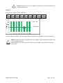
1
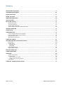
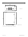
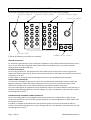
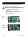
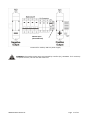
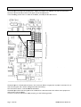
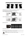
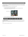
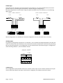
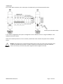
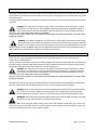
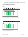
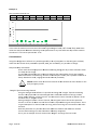
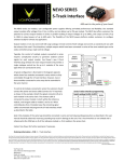
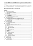
STRING BOX
Connection Box & Monitoring
Page 2 of 32
0MNA137A55‐GB Rev.01
Installation and user manual
RPS SpA
via Somalia, 20
20032 Cormano (MI)
Tel. +39 02 66327.1
Fax +39 02 66327.231
www.aros-solar.com
The reproduction of any part of this manual is forbidden, even if partial, unless authorized by manufacturer.
The manufacturer reserves the right to modify the described product in any moment without notice.
0MNA137A55‐GB Rev.01
Page 3 of 32
ICONS
DANGER!!
WARNING!!
NOTICE!!
This icon warns you about a procedure that if not
correctly executed can lead to serious accident or
death.
This icon warns you about a procedure that if not
correctly executed can lead to damage to the
equipment.
This icon indicates important info about the
equipment.
Individual Safety Equipment
During maintenance operations is forbidden to operate without Individual Safety Equipment indicated
below.
The installation or maintenance personnel must NOT wear garments with wide sleeves, laces, belts,
bracelets or other dangerous garments, especially if metallic.
Any long hair must be collected in order to not to be a danger.
The following icons represent the individual safety equipment to be worn. The equipment should be
determined and chosen in relation to the kind of danger (especially the electric one) to be faced.
Accident prevention footwear
Use: ALWAYS
Protective goggles
Use: ALWAYS
Protective garments
Use: ALWAYS
Helmet
Use: in case of presence of suspended
loads
Insulated protective gloves
Use: ALWAYS
Definition of operators and technicians
The personnel doing ordinary maintenance on the equipment are defined as “operators”. These personnel
are aware about operating and maintenance modes of the equipment. These personnel must have the
following requirements:
He/she has done a training to be enabled to operate according to current safety standards in relation to
the electrical shock danger
He/she has done training on Individual Safety Garments and on basic First Aid
The personnel intended to install, first activation and to possible extraordinary maintenance are defined to
be “technicians”.
These personnel must possess the operator’s requisites, and moreover:
He/she must be trained by the manufacturer (or by a deputy)
He/she must know the installation, assembly, repair and service modes; he/she must also have a specific
technical qualification.
In general he/she has done a technical or specific training on use and security maintenance of the
equipment.
Page 4 of 32
0MNA137A55‐GB Rev.01
Emergency Actions
General information follows.
First Aid
Follow corporate regulations and traditional first aid procedures.
Fire Fighting Measures
Don’t use water for fire fighting, but only fire extinguishers especially made for electrical
and electronic equipments. Some equipment when in fire can release toxic fumes into
the atmosphere: during fire fighting always use a respirator.
0MNA137A55‐GB Rev.01
Page 5 of 32
Thank you for choosing our product.
AROS is specialized in the development and production of equipments for statically converting energy. The
“String Box” is a high quality product carefully designed and constructed to ensure the best performance.
GENERAL WARNINGS
This manual contains the description of the use, installation and startup of the String Box.
Read carefully this manual before installation or use.
Due to the information contained about use of the equipment, the manual must be
preserved with care; it must be examined before any operation on the equipment itself.
Operating Instructions
This equipment is intended for professional use only, in industrial or commercial
environments. The relay connections must be done with shielded electrical wire.
Warning
This product is intended for sale to professional installers only. In order to prevent
electrical noise, some installation restrictions or additional devices are possible.
SECURITY RECOMMENDATIONS TO FOLLOW DURING INSTALLATION AND USE OF THE EQUIPMENT.
• The very first thing to do is to connect the ground wire to the clamp with the symbol
•
•
•
•
The equipment must NOT operate without ground connection.
The equipment must be installed and used according to the instructions contained into
this manual
The equipment has ELECRICAL PARTS ALWAYS LIVE, the operators and the technicians
must be adequately trained on operations on ELECTRICAL CIRCUITS ALWAYS LIVE, and
must always wear INDIVIDUAL SAFETY EQUIPMENT
Inside the equipment are always present dangerous voltages, even with the switch in open
position. In order to safely access the equipment, disconnect all the strings coming from
the PV array, always wearing the individual safety equipment.
The technician must strictly follow the indications related to the installation and maintenance of the
equipment:
• Always use insulated tools
• Always use individual safety equipment
• Respect the polarity
• If necessary, substitute the fuses, using same type.
• Always follow the local existing legislation in order to correctly dispose the removed parts
• Do not deactivate security devices, do not ignore alarms and warnings, being these
described into this manual or highlighted with plates or labels on or within the equipment.
• Promptly substitute the security warning plates or labels when unreadable.
• Use the equipment with mounted protections and the front door closed. During
maintenance of the equipment never remove at the same time both transparent
protections on the power boards.
Page 6 of 32
0MNA137A55‐GB Rev.01
•
•
•
•
•
•
To modify, manipulate or in any way change the structure of the equipment is in any case
forbidden without manufacturer’s authorization.
All the maintenance operations must be written on a special logbook; any operation must
have date and time, the nature of the operation, name of the operator and all the useful
information.
When all the maintenance operations are over, a careful check must be done, in order to
do not forget any tool or extraneous material inside the equipment.
In case of faults or malfunctions the local dealer or the manufacturer must be contacted;
only qualified technicians can do the necessary repair operations.
It’s exhaustively forbidden to wash the electrical parts, inside or outside the equipment.
Both storage and installation places must respect the environmental requirements
reported in this manual.
CE Marking
The equipment described in this manual adheres to the following directives:
LV Directive 2006/95/EC.
EMC Directive 2004/108/EC.
The reproduction of any part of this manual is forbidden, even if partial, unless authorized by manufacturer. The manufacturer
reserves the right to modify the described product in any moment without notice.
0MNA137A55‐GB Rev.01
Page 7 of 32
Summary
DESCRIPTION OF EQUIPMENT ................................................................................................................................ 9
CONFIGURATION SOFTWARE ............................................................................................................................... 10
INSTALLATION PLACE ........................................................................................................................................... 11
BEFORE YOU BEGIN ............................................................................................................................................. 11
DIMENSIONS AND WEIGHT .................................................................................................................................. 12
WALL MOUNTING ................................................................................................................................................ 13
INPUTS AND OUTPUTS ......................................................................................................................................... 14
Ground connection: ................................................................................................................................................ 14
PV Field connections: ............................................................................................................................................. 14
Output cables connection: ..................................................................................................................................... 14
Communication and power cables connection: ..................................................................................................... 14
GROUND CONNECTION........................................................................................................................................ 15
POWER SUPPLY ................................................................................................................................................... 16
COMMUNICATIONS ............................................................................................................................................. 18
2‐wire connection with screw connectors .............................................................................................................. 19
4‐wire connection with screw connectors .............................................................................................................. 19
RJ45 connector pinout............................................................................................................................................ 19
Optional SLOT connection ...................................................................................................................................... 19
STRING BOX ADDRESS ......................................................................................................................................... 20
MEASURES AND ALERTS, INPUTS AND OUTPUTS .................................................................................................. 21
PT100 input ............................................................................................................................................................ 22
Analog inputs ......................................................................................................................................................... 22
4‐20 mA input ....................................................................................................................................................................... 22
0‐10V input ........................................................................................................................................................................... 23
Isolated digital inputs............................................................................................................................................. 24
Digital outputs (relays)........................................................................................................................................... 24
INVERTER CONNECTION....................................................................................................................................... 25
STRING CONNECTIONS......................................................................................................................................... 25
OPERATION ......................................................................................................................................................... 26
Default configuration ............................................................................................................................................. 26
Customizations ....................................................................................................................................................... 28
Daily and Yearly time masks.................................................................................................................................................. 28
“Weight” of the measuring channel...................................................................................................................................... 28
LED behavior .......................................................................................................................................................... 30
STRING BOX: TECHNICAL SPECIFICATIONS ............................................................................................................ 31
Page 8 of 32
0MNA137A55‐GB Rev.01
DESCRIPTION OF EQUIPMENT
2
3
2
S
R
5
8
4
S
R
)
l
a
n
o
i
t
p
o
(
.
h
t
e
t
c
a
t
n
o
c
L
O
R
T
TI
N
N
OU
C
Y
RP
L
E
WU
P
O
PS
P
V
O
n
o
i
t
a
i
d
a
r
r
I
e
r
u
t
a
r
e
p
m
e
T
r
o
s
n
e
s
A
m
0
2
/
4
d
l
e
i
F
V
P
y
l
p
p
u
s
r
e
w
o
p
)
c
a
a
Vl
n
0
3
i
2o
t
X
o
Up
A(
t
c
a
t
n
o
C
STRING BOX general scheme and main connections available
0MNA137A55‐GB Rev.01
Page 9 of 32
The String Box is equipment that allows the parallel connections of the strings of a PV field; at the same
time the String Box protects the strings with a fuse.
A sophisticated monitoring system within the String Box checks the status of any measure channel.
The key features of the String Box are:
• Parallel connection of (up to) 16 strings by 9A each (8 channels)
•
Local and remote indication of status and alarm conditions
•
RS232 and RS485 connections
•
One SLOT connection for expanding communication (e.g. Ethernet board)
•
Proprietary communication protocol and MODBUS RTU, both available on all the
communication ports, no configuration necessary, hot‐swap.
•
Wide configurability of the monitoring parameters using the available software
•
Local history log of alarms and status
•
Protection fuses for each couple of inputs, 900Vdc on positive and negative
•
For each input is possible to connect wires up to 16mm2
•
Output switch, with optional release coil, used for inverter detachment
•
Monitored discharger, used against over‐voltage situations, protected against over‐
currents, easy to restore thanks to removable cartridges.
•
Direct input power from PV field or from auxiliary
•
Insulated digital inputs for local monitoring
•
Insulated analog inputs for environmental sensors (2xPT100, 0‐10V, 4‐20mA)
•
Configurable digital outputs with free contacts
•
IP65 protection degree for external environment.
CONFIGURATION SOFTWARE
This manual refers to String Box configuration software; this software is not provided with the equipment,
but is downloadable from the manufacturer’s web site or from the following site, in the Photovoltaic
Section:
http://www.aros.it
The software is available for Windows only; within the same page is possible to download the software
manual, in pdf format.
Page 10 of 32
0MNA137A55‐GB Rev.01
INSTALLATION PLACE
The String Box equipment has been designed for external installation. For the installation choice, read the
following notes:
•
The String Box must be installed with wire connection side facedown.
•
The String Box can be wall mounted, using the accessories provided. Be sure the wall
chosen is able to withstand the weight.
•
The mounting surface must not be flammable (e.g.: wood)
•
Although the equipment is designed for external environments, it’s necessary to protect it
from direct sunlight; otherwise the internal temperature could damage the components.
•
Do not install in places exposed to hot air.
•
Do not install in spaces too narrow: these could obstruct the normal maintenance
operations and the necessary air exchange.
•
Leave an empty 30cm all around the equipment.
•
The temperature of the installation environment must be within:
‐20 ÷ +45°C (operating)
‐20 ÷ +60°C (storage)
BEFORE YOU BEGIN
When you receive the equipment verify that packaging is not damaged.
Pay attention when removing the packaging in order to avoid scratches.
The String Box must be handled with care, any bumps and falls could damage the equipment.
This manual is provided with the String Box. The manual must be carefully preserved and must be
examined before any operation on the equipment.
Packing list:
•
String Box
•
This manual
•
Wall mounting installation kit (4 wall mounting accessories and 4 screws)
•
20 caps for cable gland kit (M16)
•
Additional complete cable gland kits (6xM16 + 2xM32)
0MNA137A55‐GB Rev.01
Page 11 of 32
DIMENSIONS AND WEIGHT
5
8
5
0
0
3
0
4
8
0
0
8
Bottom view
Front view
[Dimensions in mm]
The String Box standard configuration weight is 27 Kg (59,52 lb)
Page 12 of 32
0MNA137A55‐GB Rev.01
WALL MOUNTING
The String Box can be wall mounted. The wall mounting kit is composed by 4 rods and the necessary
screws.
WARNING: All the mounting rods and screws must be used. The wall mounting screws are not
included in the kit and should be chosen depending on the wall solidity.
5
2
x
4
S
L
L
I
R
D
L
L
A
W
)
m
m
n
i
n
o
i
s
n
e
m
i
D
(
1
1
0
4
0
1
1
7
0
5
3
4
6
5
0
7
0MNA137A55‐GB Rev.01
5
4
8
Page 13 of 32
INPUTS AND OUTPUTS
t
u
p
n
i
g
n
i
r
t
s
e
v
i
t
i
s
o
P
t
u
p
n
i
g
n
i
r
t
s
e
v
i
t
a
g
e
N
t
u
p
t
u
o
e
v
i
t
a
g
e
N
All the input and output cables must be connected using the lower part of the String Box
t
u
p
t
u
o
e
v
i
t
i
s
o
P
e
l
b
a
c
d
n
u
o
r
G
s
e
l
b
a
c
n
o
i
t
a
c
i
n
u
m
m
o
C
In detail the following connections are available:
Ground connection:
To connect the ground cable, use the cable gland capable to accept cables with external diameter from 5
up to 12 mm. Internally the ground cable can be fastened to the M8 screw, so the cable should be
prepared with a suitable crimp loop.
PV Field connections:
For the string connections, the equipment has 2x16 cable glands (16 for positive, 16 for negative) for
cables with diameter from 4 up to 10 mm. The maximum section for the cables connectable to the internal
connections is 16 mm2.
If some inputs are not used, close the cable glands with the caps supplied with the String Box.
Output cables connection:
To connect the String Box to the inverter, there are two cable glands (indicated as Positive output and
Negative output), for cables with external diameter from 11 to 21 mm. Internally the cables can be
fastened to the M8 screws, so the cables should be prepared with suitable crimp loops.
Two more cable glands are supplied for those installations where two parallel cables for each polarity are
needed. See the following figure for a correct drilling in this case. The diameter of the drill hole to install
the cable glands is 32 mm.
Communication and power cables connection:
There are 3 cable glands on the String Box that must be used for the communication cables, for the
environment sensors and for the auxiliary power (optional). The external diameter for these cables must
be within 4 to 10 mm.
If needed, it’s possible to drill the bottom side of the String Box to increase the number of cables to
connect. See the following figure for a correct drilling in this case. The diameter of the drill hole to install
the cable glands is 16 mm.
Page 14 of 32
0MNA137A55‐GB Rev.01
5
5
5
5
0
3
0
3
0
3
0
3
Optional cable glands placement
GROUND CONNECTION
DANGER: The very first connection to be made on the String Box is the ground cable. Apart from
security reasons, this connection grants the proper operation of the overvoltage dischargers
within the equipment.
For this purpose a ground cable with minimal 25 mm² section must be connected to the correct screw (see
below).
Ground cable connection
0MNA137A55‐GB Rev.01
Page 15 of 32
POWER SUPPLY
The String Box needs a power supply in order to evaluate measures and to communicate.
This power supply can be provided by the PV field or optionally by an auxiliary 230Vac (+/‐ 20%).
In the factory configuration the String Box is configured to be supplied from the PV field, if PV field voltage
is greater than 200 Vdc.
In order to use the auxiliary power supply apply the following procedure:
DANGER: Follow this procedure BEFORE connecting the PV field and the auxiliary power
supply to the String Box.
•
•
•
•
•
•
Verify that the output switch SW‐OUT is in the OPEN position
With a multimeter verify that no dangerous residual voltages are present on the positive
and negative terminals
Locate the power supply board inside the String Box and remove the transparent security
cover. (See picture below, where you see the default configuration).
Disconnect the cables connected to J1 and J2 and swap positions, as shown in the second
picture.
Restore the transparent security cover.
Apply 230 Vac on the terminals on the DIN bar as indicated in the third figure.
J1 connector
(Red & black)
J2 connector
(Blue & black)
PV field powers the equipment (default)
J1 connector
(Blue & black)
J2 connector
(Red & black)
Auxiliary 230 Vac powers the equipment
Page 16 of 32
0MNA137A55‐GB Rev.01
230Vac input
(Phase‐Neutral)
Terminals for auxiliary 230 Vac power supply
WARNING: The auxiliary power input is protected by a 4A fuse (F1), 10x38mm. If it’s necessary
to replace the fuse, use one with the same kind.
0MNA137A55‐GB Rev.01
Page 17 of 32
COM
MMUNICATIONS
The String Box
B has manyy connection
n options. Th
hese connecttions are avaailable into th
he microprocessor
board (or co
ontrol board
d), located at the upper side of the eq
quipment.
In the follow
wing picture there is a vieew of the bo
oard, and the
e possible co
onnections:
Configuratio
on jumpers for
f RS485
RS485 connectio
ons, RJ45‐A
and RJ45‐B
RS232 co
onnection (ffemale DB9)
The RS232 port
p is a fem
male DB9 connector; this connector alllows a singlee point‐to‐po
oint connecttion of a pc
with the Strring Box and it allows con
nfiguration and
a monitoriing.
The connecction cable is a standard RS232
R
DB9 cable.
c
The RS485 port
p allows the
t String Bo
ox to be conn
nected to a communicati
c
on bus wherre more equipments
and inverters can be preesent.
In order to make this co
onnection wo
ork properly,, see the following picturre:
Page 18 off 32
0MN
NA137A55‐G
GB Rev.01
2 wire connection
without termination
5
P
J
1
2
3
2 wire connection
with termination
5
P
J
1
2
3
4 wire connection
without termination
5
P
J
1
2
3
4 wire connection
with termination
5
P
J
8
P
J
8
P
J
8
P
J
8
P
J
6
P
J
6
P
J
6
P
J
6
P
J
7
P
J
7
P
J
7
P
J
7
P
J
1
2
3
The RS485 connection can be done using the screw connectors or the RJ45 connectors; all the connectors
are connected in parallel, so any combination of two in‐and‐out can be chosen.
See the following pictures for the two or four wires 485 connections:
2‐wire connection with screw connectors
Notice: verify the jumper settings.
4‐wire connection with screw connectors
Notice: verify the jumper settings.
RJ45 connector pinout
PIN
2 wires
1
2
3
4
5
6
7
8
N.C.
N.C.
N.C.
A+
AN.C.
GND
N.C.
4 wires
N.C.
N.C.
R+
T+
TRGND
N.C.
Optional SLOT connection
The String Box offers an additional expansion slot in order to use optional communication cards. See
proper communication card documentation for a detailed explanation.
WARNING: In order to avoid damage to equipment and communication card, use cards
specifically designed for use in conjunction with the String Box.
0MNA137A55‐GB Rev.01
Page 19 of 32
STRING BOX ADDRESS
The String Box address can be configured using the SW1 dip‐switch. Equipments on the same bus must not
have the same address, so it’s necessary to verify that also the inverters connected on the same RS485 bus
have all different addresses.
To change the address of the String Box, use the following procedure:
•
•
Locate the microprocessor card inside the String Box
On the card locate the SW1 dip‐switch bank, numbered from 1 to 8. Warning: the correct
numbering is always in the serigraphy on the card.
Dip‐switch bank
•
Set the correct address using binary encoding:
SW (serigraphy)
Value
1
1
2
2
3
4
4
8
5
16
6
32
7
64
8
‐
The real address is the sum of all values set to ON position, so if you set to ON the dip switches 1 and 4,
the String Box address is 9.
This address is used for all the communication ports (RS485, RS232 and SLOT) and for both Sunvision and
Modbus protocol. The valid addresses range from 1 (just switch 1 to on) to 127 (all switches from 1 to 7
ON).
NOTE: The switch 8 is reserved for future use.
Page 20 of 32
0MNA137A55‐GB Rev.01
MEASURES AND ALLERTS, INPU
UTS AND OU
UTPUTS
The String Box
B has somee analog inputs to conneect external sensors.
s
Speccifically availlable:
•
•
•
o (2) PT100 analog
a
inputs with 2 or 3‐wire
3
connection (J9 con
nnector). Theese inputs arre
Two
galvvanically isolated respectt to the card’s electronicc.
Onee (1) 4‐20 mA
A analog input, J7 connector. This inp
put is galvanically isolateed and can be
e
con
nfigured by software.
Onee (1) 0‐10V analog
a
input,, J7 connecto
or. This inputt is galvanicaally isolated aand can be configured
by software;
s
thee default con
nfiguration iss for a solar radiation sen
nsor in rangee 0‐1200W/m
m2. For
con
nvenience there is a 12Vd
dc on the sam
me connecto
or for the pow
wer of the so
olar radiation sensor.
In the follow
wing figure the two conn
nectors J7 an
nd J9 are high
hlighted; theey are located
d on the
microprocessor card.
J
J7
J9
.
0MNA137A
A55‐GB Rev.0
01
Page 21 of 32
PT100 input
N
O
I
T
C
E
N
N
O
C
E
R
I
W
2
0
0
1
T
P
N
O
I
T
C
E
N
N
O
C
E
R
I
W
3
0
0
1
T
P
The PT100 sensor connection to the J9 connector can be done in 2 or 3‐wire configuration (this ensures
greater accuracy in measuring the temperature, compensating the voltage drop)
The two configurations can be chosen using the jumpers located close to J9 connector, as the following
figure shows:
0
0
1
T
P
0
0
1
T
P
0
0
1
T
P
0
0
1
T
P
60
0
5T
1H
2
4 PC
30
0
21
1
TH
1 PC
60
0
5T
1H
2
4 PC
30
0
21
1
TH
1 PC
4
1
P
J
9
P
J
4
1
P
J
9
P
J
Mixed configurations are allowed (one channel configured as a 2‐wire, the other one as a 3‐wire).
Analog inputs
Two generic analog inputs re present on J7 connector , one is suitable for voltages between 0 and 10V, the
other one allows 4‐20 mA transducers to be connected. The values acquired are transformed by the String
Box into physical quantities. The configuration of such transformation is possible using the “Configuration
and monitoring software”, see the software manual.
T
U
P
N
I
G
O
L
A
N
A
A
m
0
2
4
+
-
V +
0
1
0 7
J
4‐20 mA input
This configurable input by default will show 4 mA with 4 mA of input current and 20 mA with 20 mA input
current. With the software this input can be fully re‐configured, see software manual for details.
Page 22 of 32
0MNA137A55‐GB Rev.01
0‐10V input
For an easy cable connection, the 0‐10V input is located directly on the DIN‐mounted screws.
0‐10V input and 12Vdc output
In the default configuration this input is configured as a solar radiation sensor in range 0‐1200W/m2. See
software manual for details.
Close to the 0‐10V input there is also an auxiliary 12Vdc that can be used for the power of the radiation
sensor.
NOTICE: The 0‐10V input is galvanically isolated respect to the rest of the card’s electronics and
to the 12V available on the screws. In order to allow correct operation of the solar radiation
sensor is necessary to shorten the power negative and the negative of 0‐10V.
0MNA137A55‐GB Rev.01
Page 23 of 32
Isolated digital inputs
T
U
P
N
I
L
A
T
I
G
I
D
On J5 connector of the CPU card two digital isolated inputs are
available. The status of these inputs is checked by the String
Box and can be associated to an alarm. The default behavior
the alarm is generated when this input is closed, but using the
configuration software this can be changed (see flag “inverted
logic”). This can be done for each input independently.
5
J
D
N
G
1
N
I
D
N
G
2
N
I
Digital outputs (relays)
T
U
P
T
U
O
T
C
A
T
N
O
C
E
E
R
F
4
J
1
T
U
O
L
R
A
N
M
O
C
C
N
On J4 connector of the CPU card two free contacts relays are
available. See the figure to see the position of the contacts
(this figure shows the relays in a not‐excited state)
Using the configuration software is possible to assign a
specific alarm to one or both the relays. See software
manual for details.
A
N
2
T
U
O
L
R
The default configuration is the following:
RL OUT1: is related to the OR of the following alarms:
• String alarms
• Null current persistence
• Overvoltage discharger in alarm
RL OUT2: is related to ALL the available alarms:
• String alarms
• Null current persistence
• Overvoltage discharger in alarm
• Power supply voltage alarm
• Isolated digital input 1
• Isolated digital input 2
• Real time clock alarm
• Internal memory alarm
• Analog voltage reference alarm
• Calibration error
• Auxiliary contact closed
• Link alarm
M
O
C
C
N
RELAYS MAXIMUM LOAD
The graph we report here shows the maximum
load (current) that the relay can bear, in relation
to the applied voltage. For example with an
applied voltage of 30V the maximum current is
2A, whereas with 200V the maximum current is
0.3A.
Page 24 of 32
0MNA137A55‐GB Rev.01
INVERTER CONNECTION
The power cables going to the inverter must be connected on the bar screws of the DIN rail, front side of
the String Box. The polarities indicated must be respected. See the large picture located on the inner side
of the front door.
For each polarity an M8 pin is available; two cables of max 95mm2 can be connected using the correct lug
with hole.
DANGER: This equipment has internal parts always connected to the PV field and/or inverter
(always live). Any operation on the String Box should be performed by a qualified technician
only; these personnel must be adequately trained to operate on circuits ALWAYS LIVE; they
must wear the proper INDIVIDUAL SAFETY EQUIPMENT.
DOUBLE CHECK THE POLARITY OF THE CONNECTIONS IN ORDER TO AVOID EQUIPMENT, PV PANELS AND
INVERTER DAMAGE.
DANGER: The cables bringing power to the inverter can be LIVE if connected to other String
Box equipments (more than one String Box can be connected to the same inverter). Before to
operate on such cables, always open the switches of the other String Box equipments and the
switches of the inverter. ALWAYS verify that no dangerous voltages are present on the operated parts (a
digital multimeter with proper full scale can be used for this purpose).
STRING CONNECTIONS
The String Box has 8 independent measure channels with 18A maximum current; each channel is
protected by a 900V/20A fuse.
To each channel is possible to connect two cables, typically two strings of the PV field. For each polarity of
the input strings a unipolar cable with diameter from 4 to 10mm must be used. The cable terminals are
compatible with cables with section between 0.75 mm2 and 16 mm2.
DANGER: This equipment has internal parts always connected to the PV field and/or inverter
(always live). Any operation on the String Box should be performed by a qualified technician
only; these personnel must be adequately trained to operate on circuits ALWAYS LIVE; they
must wear the proper INDIVIDUAL SAFETY EQUIPMENT.
DOUBLE CHECK THE POLARITY OF THE CONNECTIONS IN ORDER TO AVOID EQUIPMENT, PV PANELS AND
INVERTER DAMAGE.
The cable terminals for the strings of the PV field have connectors that can be detached from the power
board in order to help the connection/isolation of one or more strings to/from String Box.
DANGER: When a cable terminal must be connected/disconnected to/from the power board,
the current must be NULL. Before to connect/disconnect a cable terminal on/from power
board, double check that the inverter is off and that output switch of the String Box is open.
WARNING: The positive and negative string terminals must be connected, carefully respecting
the polarity, to the cable terminals on the two power boards.
When connecting the cables, always respect the cable terminals numeration, e.g. connect the
positive of string 1 to the cable terminal 1a of the “positive” board and connect the negative of the same
string to the cable terminal 1a of the “negative” board.
0MNA137A55‐GB Rev.01
Page 25 of 32
8
7
6
5
4
3
2
1
8
7
6
5
4
3
2
1
1
1
1a 1b 2a 2b 3a 3b 4a 4b 5a 5b 6a 6b 7a 7b 8a 8b
1a 1b 2a 2b 3a 3b 4a 4b 5a 5b 6a 6b 7a 7b 8a 8b
T
U
P
N
I
G
N
I
R
T
S
E
V
I
T
I
S
O
P
T
U
P
N
I
G
N
I
R
T
S
E
V
I
T
A
G
E
N
1
g
n
i
r
t
s
+
-
+
2
g
n
i
r
t
s
WARNING: If not all the inputs are used, it’s necessary to close all the cable holes with the
supplied caps; this ensures the level of protection designed.
OPERATION
When all the connections are done and all the transparent security devices are set, it’s possible to close
the output switch in order to connect the PV field to the inverter.
DANGER: before to close the SW‐OUT output switch, be sure that no operator is working on
the cables connecting the String Box to the inverter; also be sure that no short circuits are
present.
When the PV field voltage is above 200 Vdc or when auxiliary power is used, the equipment is
powered and the string monitoring is started.
Default configuration
By default the String Box monitors all the inputs with the same number of strings. Moreover, the strings
have all the same current features, the same exposure and shading.
By default the String Box monitors from 6:00 to 21:59 of every day of the year.
Three key monitoring parameters are defined:
• Tolerance (percentage, TOLL%): is the maximum percentage of deviation of a measuring channel
respect to the channel with maximum current beyond which an alarm condition arises. The default
value is 20%.
• Intervention time (TIME_ALL): is the time (in seconds) for which the alarm condition must persist
before it is actually generated and sent to the remote control. The same interval time is applied
when there is a return from alarm condition.
• Minimum intervention threshold (percentage, MIN%): is the percentage of current below which
the comparison between the strings is not performed: if the current value of the maximum current
string is below this value, the monitoring is not performed. After two days in this null current
Page 26 of 32
0MNA137A55‐GB Rev.01
ndition, an alarm is generrated (“null current
c
persiistence”). Th
he default value is set to 10% of the
con
scale.
wing examples we simulaate the conn
nection of 16
6 strings to th
he String Boxx; different possible
p
In the follow
situations are showed: normal
n
operration, alarm
m situations.
wn.
An examplee of configuraation changee is also show
Example 1:
The currentts measured are:
ch1
ch
h2
ch3
ch4
13,5
13
3,2
13,7
12,5
ch5
13,9
cch6
1
12,0
ch7
12,9
9
ch8
13,5
channel
[A]
The maximu
um current is 13,9A, toleerance is 20%
%, so the alarrm threshold
d is 11,1A.
In this exam
mple all the current
c
are above this thrreshold, so no
n alarm is present.
Example 2:
The currentts measured are:
ch4
ch1
ch
h2
ch3
13,5
13
3,2
8,5
12,5
ch5
13,9
cch6
1
12,0
ch7
12,9
9
ch8
13,5
channel
[A]
The channeel ch3 has a current
c
below
w the threshold. If this co
ondition lasts for a time ggreater than
n TIME_ALL
parameter, the alarm co
ondition for that string iss set.
0MNA137A
A55‐GB Rev.0
01
Page 27 of 32
Example 3:
The currentts measured are:
ch4
ch1
ch
h2
ch3
1,5
1,,4
1,6
0,8
ch5
1,0
cch6
0
0,8
ch7
0,4
ch8
1,5
channel
[A]
ntage of scalee, 10% of 20A
A Æ2A). Witth these
In this case the maximum current iss less than MIN% (percen
c
b
between
thee strings is no
ot performed
d. In any casee after two d
days of this situation
s
values the comparison
the alarm of
o “null current persistencce” is set.
Customiza
ations
Using the co
onfiguration software it’s possible to
o modify a se
et of parametters on the SString Box. In
n detail,
other than the
t former three parameeters (TOLL%
%, TIME_ALL and MIN%), it’s possiblee to change:
Daily and Yeearly time masks
m
These masks have the purpose
p
to disable
d
monittoring duringg the day in tthose mome
ents when
it’s shady on
o the stringss.
It’s possiblee to divide th
he year in tw
wo parts defining the starrting date off each part to
o allow
different behavior in monitoring.
m
Fo
or each of th
he two parts of the year iis possible to
o define an
hourly‐based time massk, ranging frrom 6:00 to 22:00
2
(21:59:59).
NOTICE: Please refer to
o the user’s manual
m
of th
he software ffor more dettails on the
y
masks..
daily and yearly
o the measuring channell
“Weight” of
Using the configuration
c
n software it’s possible to
o change thee “weight” fo
or each meassuring
channel. Th
his parameteer has to be changed
c
whe
en a differen
nt number off strings or when
w
strings with
h a different nominal current are co
onnected to some
s
channeel. By default all the
channels have a “weigh
ht” of 100.
Setting a weight
w
of 50 for
f a certain channel, the
e String Box knows that o
on that particular
channel a current of ab
bout one hallf than norm
mal is expecteed during normal operatiion. This is
h one string, while two strings are co
onnected to the
t other
a typical exxample of a channel with
channels.
With this parameter
p
it’s possible to
o monitor diffferent chann
nels with diffferent nomin
nal
currents th
hat would go into alarm condition
c
if directly
d
comp
pared.
This is just an example:: for each channel the “w
weight” can range
r
from 1
10 to 100.
Page 28 off 32
0MN
NA137A55‐G
GB Rev.01
m
of thee software fo
or more detaails on the
NOTICE: Pleease refer to the user’s manual
weight of th
he channels.
Example:
Channel 6 has
h “weight” 50, the otheers 100:
ch1
14,0
cch2
1
13,5
ch3
14,0
0
ch4
14,1
ch5
13,8
cch6
7
7,0
ch7
7
13,8
ch8
14,1
channel
[A]
The thresho
old for chann
nel 6 is 50% compared
c
to
o the others and
a so the condition is o
of normal ope
eration.
NOTICE: If a channel hass no strings connected,
c
the “weight” should be seet to 0 to excclude that
channel from
m monitoring.
Alternativelyy you can set all the hourly masks of that channeel to be unch
hecked to havve the
same result.
0MNA137A
A55‐GB Rev.0
01
Page 29 of 32
LED behavior
N
O
D
E
L
On the microprocessor board there is a set of led; this set allows having a prompt visual feedback on 8
string currents.
The led corresponding to a channel stays lit for a time proportional to the measured current: so a
measured null current is indicated by a led always off, a current to full scale (20A) is indicated by a led
always lit, while a current of 10A (50%) makes its led lit for 5 seconds and off for the remaining 5 seconds.
So the led flash with a period of 10 seconds and the duty cycle (lit time / unlit time) is equal to the
measured current in relation to the full scale.
In the following figure there is a sample timeline representing led lit/unlit; the 8 channels of the sample
String Box have different current, and in the same figure there is the correspondence between each led
and the measuring channel. So LED DL4 is channel CH1, LED DL5 is channel CH2, and so on.
I
A
0
1
A
2
1
A
0
1
A
6
A
0
1
A
2
1
A
0
1
8
H
C
A
0
1
4
1
L
D
7
H
C
3
1
L
D
6
H
C
0
1
L
D
5
H
C
9
L
D
4
H
C
8
L
D
3
H
C
7
L
D
2
H
C
5
L
D
1
H
C
4
L
D
h
C
D
E
L
S
D
N
O
C
E
S
0
1
During operation, when the strings from PV field are delivering the same current, the LEDs will lit and unlit
at the same time.
NOTICE: if one or more strings are in alarm condition, the corresponding led will flash with a
1Hz frequency.
DL15 led (ACTIV) indicates the normal operation of the board and flashes with a 2Hz
frequency.
Page 30 of 32
0MNA137A55‐GB Rev.01
STRING BOX: TECHNICAL SPECIFICATIONS
General
Max input current
16 x 9A
Max output current
144A
Max voltage
880Vdc
Input screws
16+16 screw terminals
Output screws
2 bar clamps
Protection level
IP65
Operating temperature
‐20°C … +45°C
Insulation
2500Vac power/control
Protection
Overvoltage discharger
‐ Type 2
‐ 1000V max
‐ 40KA (total 8/20µs)
‐ 12.5KA (nominal 8/20µs)
‐ 25KA (max 8/20µs)
‐ 3 varistors configuration
‐ Self‐protected with fuse
‐ Monitored
General output switch
4x125A (2 poles in parallel)
String fuse
20A 900Vdc 10x38
Auxiliary power fuse
4A 500Vac 10x38
Alarms
String alarms
Null current persistence alarm
Overvoltage discharger alarm
Isolated digital input 1 status
Isolated digital input 2 status
Power supply voltage alarm
Real time clock alarm
Internal memory alarm
Link alarm (no connection to power board)
Calibration error
Auxiliary contact closed (tamper)
0MNA137A55‐GB Rev.01
Page 31 of 32
Communications
Standard
‐ 1 x RS232 (DB9 female)
‐ 1 x RS485 (RJ45 + screws)
‐ expansion communication slot
Speed
‐ 9600 bps
Insulation
‐ 2500Vac x 1 minute (232 e 485)
‐ Slot NOT insulated
Addressing
‐ From 1 to 127 (dip‐switch selection)
Output relays
Number of relays
2
Contact
‐ Exchange/potential free
‐ max. 2A
‐ max. 220Vdc / 250Vac
‐ max. 60W /62.5VA
‐ resistance < 35 mΩ
Insulation
1000 Vac
Mechanical properties
Dimensions(lxhxp)mm
600x840x300 mm
Weight
27Kg (59,52 lb)
Page 32 of 32
0MNA137A55‐GB Rev.01