1
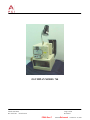
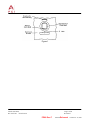
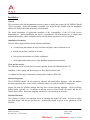
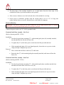
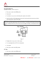
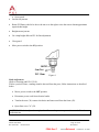
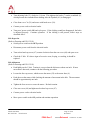
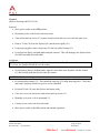
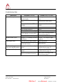
OLYMPIAN MODEL 740
Operation and Service Manual
P/N 133911-102
FCI MANUAL P/N 133865-001
Data herein has been verified and validated and believed adequate for the intended use. If the machine
or procedures are used for purposes beyond the capabilities specified, FCI does not guarantee results
and assumes no obligation or liability. This publication is not a license to operate under, nor a
recommendation to infringe upon, any process patents.
FCI Communications, Data & Consumer Division
Issued: (04/10/92)
Rev. 09/27/02
ECR V21534
Manual Part No. 133865-001
Page 1 of 20
Revision F
PDM: Rev:F
STATUS:Released
Printed: Jan 19, 2003
OLYMPIAN MODEL 740
FCI Communications, Data & Consumer Division
Issued: (04/10/92)
Rev. 09/27/02
ECR V21534
Manual Part No. 133865-001
Page 2 of 20
Revision F
PDM: Rev:F
STATUS:Released
Printed: Jan 19, 2003
Table of Contents
INTRODUCTION ..........................................................................................................................................4
Scope of Manual ...........................................................................................................................................4
Machine Function (Press)...............................................................................................................................4
Specifications ...............................................................................................................................................4
Safety Precautions.........................................................................................................................................5
INSTALLATION ...........................................................................................................................................7
General........................................................................................................................................................7
Installation Precautions ..................................................................................................................................7
Tools and Accessories....................................................................................................................................7
Machine Inspection .......................................................................................................................................7
Machine Placement .......................................................................................................................................7
Electrical Hook-Up........................................................................................................................................8
Terminal Guide Plate Assembly – Side Feed.....................................................................................................8
Terminal Guide Plate Assembly – End Feed .....................................................................................................8
Reel Bracket.................................................................................................................................................9
Safety Guard .............................................................................................................................................. 10
OPERATION ............................................................................................................................................... 11
General...................................................................................................................................................... 11
Controls and Indicators ................................................................................................................................ 11
Press Cycle Description ............................................................................................................................... 11
Manual Cycling of Press – PIC Installed......................................................................................................... 11
Manual Cycling Press – without PIC.............................................................................................................. 11
Semi-Automatic Operation ........................................................................................................................... 12
SERVICE..................................................................................................................................................... 13
PIC Changeover – End Feed ......................................................................................................................... 13
PIC Changeover – Side Feed ........................................................................................................................ 14
Ram Height Adjustment............................................................................................................................... 15
Brake Adjustment ....................................................................................................................................... 16
Belt Inspection............................................................................................................................................ 17
Belt Adjustment .......................................................................................................................................... 17
Flywheel .................................................................................................................................................... 18
Service ...................................................................................................................................................... 19
Parts Replacement....................................................................................................................................... 19
Troubleshooting Chart ................................................................................................................................. 20
REFERENCE DRAWINGS
133911-001
133927-001
144758-001
EPL, Olympian 740 X-View, Figure 8
OL740 Electrical Schematic
Electrical Schematic OL740 – (4 Pole Power Switch)
REFERENCE DOCUMENTS Delete any form references below that are not needed:
FORM #E-3245 - -Customer Application Machine Warranty and Service Policy
“Section I” Equipment owned by FCI Electronics.
FORM #E-3244 - -Customer Application Machine Warranty and Service Policy
“Section II” Equipment purchased by the customer.
FORM # E-3247- - FCI Electronics Address List
FCI Communications, Data & Consumer Division
Issued: (04/10/92)
Rev. 09/27/02
ECR V21534
Manual Part No. 133865-001
Page 3 of 20
Revision F
PDM: Rev:F
STATUS:Released
Printed: Jan 19, 2003
Introduction
Scope of Manual
This manual contains the information necessary to understand, install, operate, maintain, and order
parts for the OLYMPIAN Model 740. This information is intended for use by both operator and
service personnel. However, certain procedures within the manual should be performed by service
personnel only: these procedures are identified by a warning instruction. The table of contents in the
front of the manual gives a paragraph-by-paragraph breakdown of the subject matter covered in each
section.
WARNINGS, CAUTIONS, and NOTES within the text of this manual are used to emphasize
important and critical instructions.
WARNING: An operating procedure, practice, etc. which, if not carefully followed, could
result in personal injury or affect the operator's health.
CAUTION: An operation procedure, practice, etc. which, if not strictly observed, could result
in damage of equipment.
NOTE: An operating procedure, condition, etc. which it is essential to highlight.
We recommend that operator or service personnel responsible for maintenance of the Model 740
become thoroughly familiar with all aspects of the machine's construction and operation. If operational
or maintenance problems arise which are beyond the scope of this manual, contact your district service
representative.
Machine Function (Press)
The OLYMPIAN Model 740 is a semi-automatic bench press with a rolling clutch providing high
production speed. With a properly installed Precision Interchangeable Crimper (PIC), this unit
provides a stable, high quality, discrete crimp-to-wire termination.
Specifications
General
Dimensions (allowing for 24 inch reel of terminals)
•
•
•
•
•
•
•
Length......................................................................................................... 71.1 cm (28 in.)
Width Front and Rear Cover Open .............................................................. 78.7 cm (31 in.)
Width ......................................................................................................... 55.8 cm (22 in.)
Width with Side Guard Open ..................................................................... 93.9 cm (37 in.)
Height ...................................................................................................... 111.7 cm (44 in.)
Weight ....................................................................................................... 95 kg (209 lbs.)
Application Rate ...................................... 2,400 per hour (depending on operator dexterity)
FCI Communications, Data & Consumer Division
Issued: (04/10/92)
Rev. 09/27/02
ECR V21534
Manual Part No. 133865-001
Page 4 of 20
Revision F
PDM: Rev:F
STATUS:Released
Printed: Jan 19, 2003
Electrical Requirements
• Power.............................................................................................. 115V ac, 60Hz 1 Phase
• Motor.................................................................................. 115V ac, 50/60 Hz. 1730 RPM
4 PH – 6.1 A – Capacitor Start Motor
185 uf Capacitor
• Fuse ............................................................................................................................. 10A
• Power Cord Length .......................................................................................... 1.8 m (6 ft.)
• Press Rating .............................................................................................. 1814 Kg (2 Ton)
CAUTION: Wire Color-coding in press may not comply with J.I.C. Standards.
Safety Precautions
Press must be bolted to a sturdy workbench utilizing four boltholes in the casting base. This is required
to prevent press from vibrating and possibility falling from bench.
Turn power switch to the OFF position before opening hinged doors of the safety guard, and before
making any adjustments.
WARNING: To avoid the possibility of an electrical shock. Disconnect the power cord from its outlet
before opening the front door of the press.
The hand crank, for manual cycling the press, is fitted with an internal spring. When the inward
pressure is released from the hand crank, it should disengage from the crankshaft of the press.
WARNING: The hand crank must be removed from the crankshaft before the power switch is
switched to the ON position to prevent bodily injury or damage to the equipment.
After rotating the crankshaft by hand and before switching the press' power switch to the ON position,
make sure that the mark on the square-ended shaft at the rear of the press is in alignment with the 0º
mark (refer to Figure 1). Failure to properly position the mark will cause a rattling noise when the
power is moved to the ON position or could cause the fuse to blow.
WARNING: Personnel other than maintenance should never operate the bench press without the
safety guard in the closed position.
FCI Communications, Data & Consumer Division
Issued: (04/10/92)
Rev. 09/27/02
ECR V21534
Manual Part No. 133865-001
Page 5 of 20
Revision F
PDM: Rev:F
STATUS:Released
Printed: Jan 19, 2003
Figure 1
FCI Communications, Data & Consumer Division
Issued: (04/10/92)
Rev. 09/27/02
ECR V21534
Manual Part No. 133865-001
Page 6 of 20
Revision F
PDM: Rev:F
STATUS:Released
Printed: Jan 19, 2003
Installation
General
This section provides the information necessary to inspect, install, and prepare the OLYMPIAN Model
740 for operation. Before the machine is installed, you should become familiar with the Installation
and Service Policies provided in the back of this manual.
The initial installation of application machines is the responsibility of the FCI Field Service
Representative. During installation, the Service representative will demonstrate how to operate and
maintain the machine, and is available to assist with any future operation or service problems.
Installation Precautions
Take the following precautions during machine installation:
• Avoid placing the machine in dusty locations and places where vibrations occur.
• Handle the machine carefully at all times.
• Never place the machine on a flimsy workbench.
• Wear lightweight leather gloves when handling equipment and terminals.
Tools and Accessories
The following is a list of tools and accessories supplied for the OLYMPIAN Model 740:
Reel Boss, Collar, spring, and Reel Stopper for Reel Bracket Hand Crank
A complete tool kit may be obtained by ordering Part Number 142487-001.
Machine Inspection
The OLYMPIAN Model 740 was inspected, adjusted, and tested before shipment. After the machine
has been unpacked, place it on a sturdy workbench where it is easily accessible for inspection.
Inspect all items for possible damage that may have occurred during shipment. Check for dents,
broken knobs, switches, etc. If damage or missing items are found, notify the carrier and the FCI
District Sales Office. Retain any shipping containers in case repacking is necessary.
Machine Placement
The operators' comfort is an important factor in operating the Model 740 safely. In order to reduce
operation fatigue and increase productivity, consideration should be given to the placement of the
machine.
FCI Communications, Data & Consumer Division
Issued: (04/10/92)
Rev. 09/27/02
ECR V21534
Manual Part No. 133865-001
Page 7 of 20
Revision F
PDM: Rev:F
STATUS:Released
Printed: Jan 19, 2003
• The front edge of the machine should be six to eight inches from the front edge of the
workbench in order to prevent discomfort to the operator.
• Allow room to obtain access to the back and sides of the machine for servicing.
• Secure press to workbench, possibly using the carriage bolts (5-16 in. X 2.5 in. long with
washer and nut) that were used to fasten the press to the pallet for shipment.
Electrical Hook-Up
WARNING: The power switch on the press should be in the OFF position prior to electrical
connection to prevent possible bodily injury by premature operation.
Connect the power cord to an 115V, 60 Hz grounded outlet.
Terminal Guide Plate Assembly – Side Feed
(Refer to drawing and EPL 133911)
Installation
• Turn bar for guide plate mounting (57), with terminal guide plate (48) assembly attached,
into threaded hole on left side of frame (58).
• To tighten bar (57) to the frame, place wrench onto the flats provided and turn.
• If the terminal guide plate (48) is not aligned properly, loosen the two cap screws in the
clamp and align. Retighten cap screws.
Removal
• Place wrench onto the flats on the bar (57) and loosen.
• Rotate the bar (57) with terminal guide plate assembly attached, until removed from the
frame (58).
Terminal Guide Plate Assembly – End Feed
(Refer to drawing and EPL 133911)
Installation
• Turn bar for guide plate mounting (57), with terminal guide plate assembly attached, into
threaded hole on the back of the rear cover (60).
• To tighten bar (57) to the frame, place wrench onto the flats provided and turn.
• If the terminal guide plate (48) is not aligned properly loosen the two cap screws in the
clamp and align. Retighten cap screws.
FCI Communications, Data & Consumer Division
Issued: (04/10/92)
Rev. 09/27/02
ECR V21534
Manual Part No. 133865-001
Page 8 of 20
Revision F
PDM: Rev:F
STATUS:Released
Printed: Jan 19, 2003
Removal
• Place wrench onto the flats on the bar (57) and loosen.
• Rotate the bar (57) with terminal guide plate assembly attached, until removed from the
frame (58).
Reel Bracket
(Refer to drawing and EPL 133911)
Side Feed
• Position reel bracket (49) as shown and tighten cap screws on right of frame (58) against flat
on bracket.
• Install the rear reel boss (50), with clamp bolt (52) attached, then the spring (53) and collar
(54).
• Install reel of terminals so that terminals unreel from the left side, with the U-shaped barrels
up.
• Then install reel stopper (51) and front reel boss (50 with clamp bolt (52) attached.
• Align reel of terminals so that it is centered with the slot in the PIC where the terminals
enter.
• Next slide the rear reel boss with spring and collar against the reel and tighten clamp bolt.
• Then slide the reel stopper and the front reel boss against the reel with light tension.
Tighten clamp bolt.
NOTE: Too much tension on the reel could cause feed problems in the PIC. If there is not enough
tension, terminals could unwind freely.
End Feed
If reel bracket is positioned as shown:
• Loosen cap screw, which secures reel bracket (49), located on right side of frame (58).
• Pivot reel bracket assembly 90o toward the right and tighten cap screw onto the flat of the
bracket.
• Install the rear reel boss (50), with clamp bolt (52) attached, then the spring (53) and collar
(54).
• Install reel of terminals so that terminals unreel with the U-shaped barrels up.
FCI Communications, Data & Consumer Division
Issued: (04/10/92)
Rev. 09/27/02
ECR V21534
Manual Part No. 133865-001
Page 9 of 20
Revision F
PDM: Rev:F
STATUS:Released
Printed: Jan 19, 2003
• Then install the front reel boss (50) with clamp bolt (52) attached.
• Align reel of terminals so that it is centered with the slot in the PIC where the terminals
enter.
• Next, slide the rear reel boss with spring against the reel and tighten clamp bolt.
• Then slide the front reel boss against the reel with light tension. Tighten clamp bolt.
NOTE: Too much tension on the reel could cause feed problems in the PIC. If there is not enough
tension, terminals could unwind freely.
Safety Guard
• To open, remove cap screws, located on the upper right and left side of guard. Front and
side will pivot open when lightly pulled at top of guards.
• To close, pivot front and side guard up and secure with cap screws.
FCI Communications, Data & Consumer Division
Issued: (04/10/92)
Rev. 09/27/02
ECR V21534
Manual Part No. 133865-001
Page 10 of 20
Revision F
PDM: Rev:F
STATUS:Released
Printed: Jan 19, 2003
Operation
General
This section provides the information necessary to operate the OLYMPIAN Model 740, and includes
operating considerations and precautions.
Controls and Indicators
There are two ON-OFF switches on the front of the press: The top switch controls the counter; the
bottom switch controls the power to operate the press. Both switches have indicator lamps, which are
lighted when switches are in the ON position. The counter on the front of the press records the number
of machine cycles.
The press is cycled when the foot switch is depressed.
Press Cycle Description
(Refer to Drawing and EPL 133911)
The exploded view shows the OLYMPIAN Model 740 bench press and its related parts. The drive
motor (22) transmits power to the pulley (21) through the V-belt (29) to the flywheel (61), which drives
the clutch assembly [retainer (2), roller (3), and clutch spring (4)]. The clutch assembly permits the
power to be transmitted to the shaft (1), which rotates and causes arms (37), (38) and (39) to function;
these three arms, in turn, causes the ram (36) to move down then up.
Manual Cycling of Press – PIC Installed
If the machine, as delivered, has PIC installed, refer to separate PIC instructions for start-up procedure
prior to hand cycle.
Manual Cycling Press – without PIC
(Refer to Figure 1)
• With the power OFF, place hand crank onto the square end of the crankshaft at the rear of the
machine.
NOTE: Continuously push in on the hand crank because of the internal spring.
• Rotating the crankshaft in the direction of the arrow, located on the outside of the rear cover
(60) will lower and raise the ram. When under power, the flywheel rotates in the opposite
direction of the arrow.
• Return crankshaft to the start position and continue turning slowly until a click sound is heard,
indicating the stripper is properly engaged on the clutch. Then rotate the crankshaft in the
opposite direction of this arrow until the mark on the end of the crankshaft is aligned with the 0º
mark at the rear of the press.
FCI Communications, Data & Consumer Division
Issued: (04/10/92)
Rev. 09/27/02
ECR V21534
Manual Part No. 133865-001
Page 11 of 20
Revision F
PDM: Rev:F
STATUS:Released
Printed: Jan 19, 2003
• Remove hand crank from crankshaft before switching on power to the press.
WARNING: The hand crank must be removed for the crankshaft before the power switch is switched
to the ON position to prevent injury or damage to the equipment.
Semi-Automatic Operation
(Refer to Figure 8)
• Move power switch to the ON position.
• Turn on light by turning switch at the top of the lamp assembly.
• Activate the counter by moving its switch to the ON position. Counter may be reset to zero by
pushing in on tab (located on left side of the counter).
• Press and release the foot switch to complete one machine cycle.
FCI Communications, Data & Consumer Division
Issued: (04/10/92)
Rev. 09/27/02
ECR V21534
Manual Part No. 133865-001
Page 12 of 20
Revision F
PDM: Rev:F
STATUS:Released
Printed: Jan 19, 2003
Service
PIC Changeover – End Feed
(Refer to Drawing and EPL 133911)
Removal
• Move power switch to the OFF position.
• Disconnect power cord from electrical outlet.
• Open safety guard.
• Push the spring-loaded lever "C" (83) toward the rear of the machine to disengage it from lever
"A" (79), and hold in this position.
• Move lever "A" (79) to the left, by pulling lever "B" (80), and release lever "C" (83).
• Slide the PIC to the rear. This releases the PIC from the press.
Installation
• Move lever "A" (79) to the left.
• Place the PIC on the base (76) to the rear of the ram bolt (87).
• Slide PIC forward, so the ram bolt (87) slides into the slot in shank "A" (102) of the PIC.
(Refer to X view of PIC in the back of this manual.)
• Position the base plate of the PIC against the back and side of stopper "A" (77).
• Push the spring - loaded lever "C" (83) to the rear and hold in this position.
• Slide lever "A" (79) to the right, seating it in the slot on the side of the PIC base plate (101).
(See X view of PIC.)
• Release lever "C" (83), which locks into lever "A" (79) to secure the PIC in position.
• Reconnect power cord to electrical outlet.
• Move power switch to the ON position.
NOTE: Refer to separate PIC instructions, in the back of this manual for start-up procedure.
FCI Communications, Data & Consumer Division
Issued: (04/10/92)
Rev. 09/27/02
ECR V21534
Manual Part No. 133865-001
Page 13 of 20
Revision F
PDM: Rev:F
STATUS:Released
Printed: Jan 19, 2003
PIC Changeover – Side Feed
(Refer to Drawing and EPL 133911)
Removal
• Move power switch to the OFF position.
• Disconnect power cord from electrical outlet.
• Open safety guard.
• Push the spring-loaded lever "C" (83) (located at the right-rear of the PIC) toward the back of
the machine to disengage it from lever "A" (79), and hold in this position.
• Move lever "A" (79) (located on the left-side of the PIC) out, and release lever "C" (83). This
frees the PIC from the base.
• Slide PIC to the left. This releases the PIC from the press.
Installation
• Move lever "A" (79) to the left.
• Place the PIC on the base (76) to the left of the ram bolt (87).
• Slide PIC to the right, so the ram bolt (87) slides into the slot in shank "A" (102) of the PIC.
(Refer to X view f the PIC in the back of this manual.
• Position the base plate of the PIC against the back and side of stopper "A" (77).
• Push the spring-loaded lever "C" (83) to the rear and hold in this position.
• Slide lever "A" (79) to the right, seating it in the slot on the side of the base plate (101) of the
PIC. (Refer to X view of PIC.)
• Release lever "C" (83), which locks into lever "A" (79) to secure the PIC in position.
• Reconnect power cord to electrical outlet.
• Move power switch to the ON position.
NOTE: Refer to separate PIC instructions, in the back of this manual for start-up procedure.
FCI Communications, Data & Consumer Division
Issued: (04/10/92)
Rev. 09/27/02
ECR V21534
Manual Part No. 133865-001
Page 14 of 20
Revision F
PDM: Rev:F
STATUS:Released
Printed: Jan 19, 2003
Ram Height Adjustment
Standard FCI Ram - (Refer to Figure 5)
• Move power switch to the OFF position.
• Open guard.
• Loosen the two cap screws, which clamp the set plate to the ram bolt.
• Insert the small end of the adjustment bar into a hole in the ram bolt and rotate the ram bolt to
obtain approximate required shut height.
NOTE: The ram bolt has gradation marks etched on the side of it. Rotating the ram bolt one mark
changes the ram height approximately 0.063 mm (0.0024 in.). As indicated on the label on the front of
the press, rotating the ram bolt to the left lowers the ram height, rotating it to the right raises the ram
height.
Figure 5
• Retighten the two cap screws on the set plate.
• Use crimp height dials on PIC for fine adjustment.
• Close guard.
• Move power switch to the ON position.
FCI Ram
• Move power switch to the OFF position.
FCI Communications, Data & Consumer Division
Issued: (04/10/92)
Rev. 09/27/02
ECR V21534
Manual Part No. 133865-001
Page 15 of 20
Revision F
PDM: Rev:F
STATUS:Released
Printed: Jan 19, 2003
• Open guard.
• Loosen ram jam nut.
• Rotate FCI Ram to the left to lower the ram or to the right to raise the ram to obtain approximate
required shut height.
• Retighten ram jam nut.
• Use crimp height dials on PIC for fine adjustment.
• Close guard.
• Move power switch to the ON position.
Jam Nut
FCI Ram
Figure 6
Brake Adjustment
(Refer to Drawing and EPL 133911)
If after a period of time, a rattling sound is detected from the press, follow instructions as described
below:
• Mover power switch to the OFF position.
• Disconnect power cord from electrical outlet.
• Turn latch screw (30) counter clockwise until unscrewed from the frame (58).
• Open front cover "A" (59).
CAUTION: If brake is adjusted too tight, this will cause the press to operate slower and affect the
production rate.
FCI Communications, Data & Consumer Division
Issued: (04/10/92)
Rev. 09/27/02
ECR V21534
Manual Part No. 133865-001
Page 16 of 20
Revision F
PDM: Rev:F
STATUS:Released
Printed: Jan 19, 2003
• Turn adjusting bolt (13) clockwise 1/4 turn. This tightens the brake (7) on the crankshaft (1),
which prevents the crankshaft from drifting after the flywheel (61) is disengaged.
• Close front cover "A (59) and secure with latch screw (30).
• Connect power cord to electrical outlet.
• Turn press' power switch ON and cycle press. If the clicking sound has disappeared, the brake
is adjusted properly. Continue operation. If the clicking is still present, follow steps as
described above.
Belt Inspection
(Refer to Drawing and EPL 133911)
• Switch power switch to the OFF position.
• Disconnect power cord from the electrical outlet.
• Turn socket head cap screw (67) counter clockwise from the rear cover (60) and open cover.
• Check the V-belt. If it shows signs of excessive wear, fraying, or cracking, it should be
replaced.
Belt Adjustment
(Refer to Drawing and EPL 133911)
• Push lightly on the V-belt. Tension is correct when the belt moves about one inch. If more
movement is detected, continue with the following procedure.
• Loosen the four cap screws, which secures the motor (22) to the motor base (6).
• Push down on the motor while checking the amount of movement in the belt. The movement
should be approximately one inch.
• Tighten the four screws to secure the motor. Recheck tension.
• Close rear cover (60) and tighten socket head cap screw (67).
• Connect power cord to electrical outlet.
• Move power switch to the ON position and continue operation.
FCI Communications, Data & Consumer Division
Issued: (04/10/92)
Rev. 09/27/02
ECR V21534
Manual Part No. 133865-001
Page 17 of 20
Revision F
PDM: Rev:F
STATUS:Released
Printed: Jan 19, 2003
Flywheel
(Refer to Drawing and EPL 133911)
Removal
• Move power switch to the OFF position.
• Disconnect power cord from the electrical outlet.
• Turn socket head cap screw (67) counter clockwise from the rear cover (60) and open cover.
• Remove V-belt (29) from the flywheel (61) and the motor pulley (21).
• Using snap ring pliers remove snap ring (32) and rear pulley bearing (25).
• Grasp flywheel firmly with both hands and pull outward. This will disengage the flywheel from
the clutch assembly and crank shaft.
Installation
NOTE: Before attempting to replace the flywheel, be certain the rollers (3) are seated into the clutch
(72). If not, the flywheel will not fit over the rollers.
• Grasp flywheel firmly with both hands, align the center hole in the flywheel with the retainer
(2), and carefully push the flywheel onto the retainer.
CAUTION: The flywheel may come loose from the crankshaft if snap ring is not properly installed.
• Re-install pulley bearing (25). Then install the snap ring (32) using snap ring pliers. Check that
snap ring is properly seated in its groove on the crankshaft.
• Re-install V-belt (29) onto the flywheel and motor pulley.
• Close rear cover (60) and secure with socket head cap screw (67).
• Manually cycle press; refer to paragraph 3-5.
• Connect power cord to the electrical outlet.
• Move power switch to the ON position and continue operation.
FCI Communications, Data & Consumer Division
Issued: (04/10/92)
Rev. 09/27/02
ECR V21534
Manual Part No. 133865-001
Page 18 of 20
Revision F
PDM: Rev:F
STATUS:Released
Printed: Jan 19, 2003
Monthly Maintenance
• Check power cords for broken wires or insulation.
• Check moving parts for wear.
• Check attaching hardware for tightness.
• Check V-belt for wear.
• Lubrication - (every 200 operating hours) Using a #1 Multi-purpose high grade grease, lubricate
through the three grease nipples on the front cover "B" (5), one on the rear of the crank shaft (1)
and one on arm "A" (37).
Service
In the event service or technical help is needed FCI Electronics provides a toll free number. For
service or technical help call 1-800-843-6911.
Parts Replacement
• PARTS REPLACEMENT:
When calling for spare parts, have part number(s) ready for the customer service person. Number(s)
can be obtained from the reference drawings located in the back of this manual. Spare part orders call 1800-222-2194 and ask for CUSTOMER SERVICE.
Recommended spare parts for the bench press (EPL 133911) are specified in the parts list by the letters
“SP” in the spare parts column.
For PIC spare parts, refer to the parts list for individual PIC.
FCI Communications, Data & Consumer Division
Issued: (04/10/92)
Rev. 09/27/02
ECR V21534
Manual Part No. 133865-001
Page 19 of 20
Revision F
PDM: Rev:F
STATUS:Released
Printed: Jan 19, 2003
Troubleshooting Chart
PROBLEM
Press will not cycle
POSSIBLE CAUSE
Power cord is not connected to
electrical outlet.
CORRECTIVE ACTION
Connect power cord to electrical
outlet.
Power cord is not connected to
press.
Connect power cord to press.
Power switch is in the OFF
position.
Move power switch to the ON
position.
Fuse blown.
Replace
Foot switch is defective.
Replace
Solenoid (23) is defective. (Fig.2) Replace
Adjust V-belt as described in the
V-belt slipping on motor pulley.
Service Section, page 18
Machine double cycles
Fatigued or broken clutch spring. Replace
Stopper (15) is binding on holder Lubricate - a few drops of light(14) (Fig.2)
weight oil.
Crimp height varies
Cap screw loose in the set plate. Tighten cap screws.
If press is fitted with adapter jam
Tighten jam nut.
nut on ram is loose.
Fuse flows when power switch Mark on crankshaft is not aligned Re-align crankshaft. Refer to
is moved to the ON position. with 0º
Operation Section, page 12
Rattling sound from press
Mark on crankshaft is not aligned Re-align crankshaft. Refer to
with 0º
Operation Section, page 12
Brake is not adjusted correctly.
FCI Communications, Data & Consumer Division
Issued: (04/10/92)
Rev. 09/27/02
ECR V21534
Adjust brake as described in the
Service Section, page 17
Manual Part No. 133865-001
Page 20 of 20
Revision F
PDM: Rev:F
STATUS:Released
Printed: Jan 19, 2003