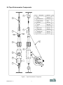
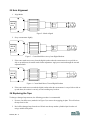
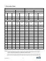
1
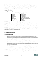
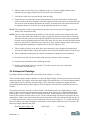
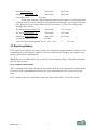
USER’S MANUAL
TAPE EXTENSOMETER
MODEL 98073-01
Serial No.______________
140 Chestnut Street
San Francisco, CA 94111 USA
Tel (415) 364-3200
Fax (415) 861-1448
[email protected]
www.geomechanics.com
Copyright ©2008 by Applied Geomechanics, All rights reserved
Document No. D00048, Rev. A
TABLE OF CONTENTS
1. Introduction and Specifications ......................................................................................................................1
1.1 Operating Principle...................................................................................................................................2
1.2 General Description..................................................................................................................................2
1.3 Digital Display..........................................................................................................................................3
2. Detailed Instructions.......................................................................................................................................3
2.1 Initial Reading ..........................................................................................................................................3
2.2 Subsequent Readings................................................................................................................................4
2.3 Replacing Battery .....................................................................................................................................5
2.4 Tape Extensometer Components ..............................................................................................................6
2.5 Axis Alignment.........................................................................................................................................7
2.6 Replacing the Tape ...................................................................................................................................7
3. Observation Sheet.........................................................................................................................................10
4 Warranty and Limitation of Liability ............................................................................................................11
1. Introduction and Specifications
The Applied Geomechanics tape extensometer is a precision instrument designed to measure the change in
distance between two points on a structure, rock mass or excavation. It is a valuable piece of equipment for
monitoring the deformation of foundations, slopes, embankments, underground openings, bridges, buildings
and other structures. This instrument is also a vital tool for investigations of tunneling, especially tunnels
constructed using the New Austrian Method of Tunneling (NATM).
NOTE: The tape extensometer is designed to measure change in distance between two points. It is not
meant for measuring actual distance between two points.
Features
•
Rugged, compact and cost effective
•
Lightweight, portable and reliable
•
Measures small changes over distances of 1m to 30m (longer tape measure available on request)
•
Heavy duty engineering steel tape
•
Large serrated knob for easy tension adjustment
•
Rapid and accurate measurement can be made with the tape extended in any direction
Table 1. Tape Extensometer and Accessory Model Numbers
Tape Extensometer
Calibration Frame
Replacement Tape
Convergence Eye Bolt and Anchor
98073-01
98073-02
98073-03
01639
Table 2. Tape Extensometer Specifications
Measurement
Length of Tape
Measurement Precision
LCD Resolution
Coefficient of Linear
Thermal Expansion of Tape
mm (inch)
1-30 m (3-100 ft.)
±0.1 mm (± 0.005 in.)
0.01 mm (0.0005 in.)
11 ppm/°C (6.11 ppm/°F)
Please note that many different factors affect structural and ground behavior and may give rise to the
deformations measured by your tape extensometer. These factors include seasonal weather changes,
temperature, rain, barometric pressure, earthquakes, traffic, construction activity, ocean tides, excavation and
sequence of construction. Personnel changes also can result in measurement differences, as the technique of
individual technicians may vary. These factors should be observed and recorded to assist in correlating data
and interpreting your measurements.
D00048, Rev. A
1
1.1 Operating Principle
The tape extensometer measures the displacement that takes place over time between two reference anchors
fixed in an excavation or structure. It is designed to accurately measure small changes in distance between
two points that may be from 1m to 30m (3 ft to 100 ft) apart.
1.2 General Description
The tape extensometer consists of a steel tape, a tape tensioning apparatus with a tension spring and tension
adjustment knob, a small digital readout and two shackles that allow the tape to be stretched between two
anchor points (Figure 1). The built-in tension spring and indexing mark allow the tape to be tensioned at a
constant value for each measurement. This permits the measurement to be made with high repeatability and a
minimum amount of sag in a horizontal, inclined or vertical direction. Note: The item numbers that
accompany the descriptions in the following pages refer to the numbered components in Figure 1.
Applied Geomechanics’ tape extensometer has an epoxy coated aluminium body (1) that houses the digital
display. The display is a five-digit LCD screen that works on a 1.5 V silver oxide (SR 44) button cell battery.
The body (1) contains a push type on/off power switch. The hole-positioning is taken from the graduate
markings on the steel measuring tape. After tension adjustment, a reading is observed on the digital display
that has a resolution of 0.01 mm (0.001 in.). Readings taken off the tape itself should only be used as a
reference. Fine readings are taken using the adjustment knob (2) and the LCD display, as described below.
To take displacement readings, the stainless attachment shackle (4) at the end of the steel tape, is hooked to
an anchor point (5) grouted in the structure or the excavation. The tape is then allowed to unreel until the
shackle on the other end (7) can be hooked to the second anchor point. The slack is taken out of the tape and
coarse tension adjustment is accomplished by inserting the engaging a pin (9) into one of the punched holes
in the steel tape. The holes are spaced at 12.5 mm (½”) intervals along the entire length of the tape. The fine
tension adjustment is achieved by rotating a serrated aluminum adjustment knob (2) that shortens the overall
length of the device until two index marks on the extensometer coincide (white mark and black mark in
Figure 1). At this point the tape is held at a standard tension by means of a spring inside the extensometer
housing. A precision digital readout measures this fine adjustment reading while the tape is held under a
constant, repeatable force. The difference from a reading that was recorded earlier gives the change in
distance between the two anchor points.
The marked graduation on the tape where the pin (9) engages the punched hole in the steel tape is used only
as a reference for taking future readings. For determining change in distance at any given time, only the
reading on the digital readout is compared with the initial reading, assuming that the same punched hole is
engaged on the pin. If the measured deformation is so large that a different hole must be used, the interval
between the two holes may be added or subtracted to the fine reading to get the total change in distance.
Note: The tape extensometer is not to be used for measuring absolute distances between two points. It only
measures the change in distance between them. Never add the reading on the tape to the digital reading to
get the correct distance between the two points. This will give you erroneous results.
Measurements, if properly taken by an experienced operator, are repeatable to within ± 0.125 mm (0.005”).
For maximum accuracy, it is recommended that the same instrument be used for each project. To check the
zero stability and accuracy of the tape extensometer, a calibration frame must be used. The Applied
Geomechanics calibration frame for the tape extensometer has an anchor distance of about one meter. The
calibration should always be done at the same temperature and in a temperature-controlled room. Whenever
the tape extensometer is used, sufficient time should be allowed for the instrument and calibration stand to
equilibrate to the ambient temperature.
D00048, Rev. A
2
It is always advisable to maintain a record of the temperature and correct the readings accordingly.
Temperature-induced lengthening or shortening of the steel tape is obtained by multiplying the thermal
expansion coefficient in Table 2 by the temperature change and then by the exposed length of the tape. For
example, if the temperature change is +10°C and the tape is unreeled to a length of 10m, the temperatureinduced lengthening is: 11 x 10-6 x 10°C x 10,000mm = 1.1mm.
1.3 Digital Display
Table 3. Digital Display Specifications
Resolution
Accuracy
Repeatability
Power
Battery Life
Operating Temperature
Storage Temperature
0.01mm/0.0005 in.
0.02 mm/0.0001 in.
0.01 mm/0.0005 in.
One SR44 (silver oxide cell)
3 years under normal operation
0°C to 40°C
-10° C to 60°C
NOTE: These specifications are for the digital display only and not for the complete extensometer.
CAUTION: If the tape extensometer is not used for more than three months, remove the battery from the
LCD compartment and store it properly. Otherwise, liquid may leak from the battery and damage the tape
extensometer.
NOTE: The digital display reads in metric units. You may change the display from metric units to English
units by first removing the LCD compartment lid by unscrewing the eight M2 x 12 screws. Then change the
display units by operating the display change pin.
2. Detailed Instructions
2.1 Initial Reading
1. Record in the Observation Chart (Section 3) the reference location, temperature and date of the
initial reading. Let the temperature of the extensometer stabilize within the location for about half an
hour before taking the reading.
2. Press the on/off pin on the digital readout of the LCD to display a reading.
3. Unscrew the extensometer serrated knob (2) to adjust the reading to approximately 000.00.
4. Hook the shackle (4) at the end of measuring tape to the eyebolt on the anchor (5) at one side of the
rock face, cavity or tunnel wall.
5. Carefully transport the extensometer to the other anchorage point, allowing the punched tape to
unreel, until the shackle on the extensometer body can be hooked on to the opposite eyebolt. Take
care that the holes in the tape measure (3) do not get entangled in the pin (9).
CAUTION: Take care that the holes in the tape measure (3) do not get entangled in the pin (9) during
winding or unwinding of the tape reel. This can damage the tape extensometer.
D00048, Rev. A
3
6. Take the slack out of the tape (3) by winding it on the reel. Loosen it slightly until the nearest
punched hole just engages with the pin (9) at the end of the extensometer.
7. Lock the lock slide (10) to prevent the tape from unreeling.
8. Tension the tape by turning the serrated adjustment knob (2) on the extensometer until the black
reference mark on the brass cylinder is accurately aligned with the white reference mark on the body.
The precision of the alignment determines the accuracy of measurement. The extensometer should
be supported all times to avoid any force on the measuring tape due to its weight.
NOTE: The extensometer must be supported by the operator to prevent the tape from sagging due to the
weight of the extensometer body.
NOTE: The axis of the extensometer body should be in line with the eyebolts on the anchors in the walls.
This can be done with a little practice by gently swaying the extensometer from side to side and up
and down and at the same time observing the alignment of the reference marks on the extensometer.
From the correctly aligned position, the black center mark will only move towards the digital readout
and never away from it. If the black center mark moves away from the digital readout, more tension
must be applied by tightening the adjustment screw. (Refer to Figures 2 to 4).
9. Take a reading of the tape at the point where the extensometer pin (9) engages the punched hole.
Also take the digital display reading. Record these in the Observation Chart (sixth row from the top).
10. Take a temperature reading at the site after the extensometer readings have been completed.
11. Unlock the lock slide (10) and carefully wind in the tape after the work is completed.
12. Clean the tape extensometer after completing the work.
13. Pack the extensometer in the case provided. To do this, it may be necessary to adjust the
extensometer serrated knob (2).
2.2 Subsequent Readings
For taking subsequent readings follow instructions given in Steps 1 to 13 above.
If the two anchor points change in distance over time, the digital display will show an increased or decreased
numerical reading. For example, assume that pin 9 engages the punched hole at 13.225m and that the digital
readout displays 14.65 at the time of initial reading. If in a subsequent reading pin 9 engages the same
punched hole and the digital readout displays 10.45, the distance between the two points has increased by
4.20mm.
The spacing of the holes in the tape is about 12.5mm. If deformation causes the digital display to reach
about 30 mm, the subsequent extensometer reading must be taken with pin (9) in a different hole than the
initial reading. This is essential to allow continuity in the data. In this situation, replace the Observation
Chart for this reference location with a new one. The new initial reading will then be referenced to the new
punched hole. Make a note at the bottom of the observation sheet to this effect and specifically note the “B –
A” reading with reference of the previous punched hole. This previous reading “B – A” reading will always
have to be added to subsequent readings to determine the correct displacement between the two points. The
following example illustrates this point:
Initial tape hole reading ‘TH’
D00048, Rev. A
(20/03/2007)
4
=
14,725 mm
Initial digital reading ‘A’
(20/03/2007)
=
20.25 mm
Subsequent digital reading ‘B’
(25/06/2007)
=
30.55 mm
Convergence (B-A)
=
10.30 mm
At this stage, because the digital reading has gone beyond 30 mm, it is essential that another
reading be taken on 25/06/07 with pin (9) in the adjacent hole of the tape. As convergence has taken
place, the pin (9) will now align with the tape hole at around 14,712.5 mm. The readings will be
something like as follows:
New initial tape hole reading ‘TH’
(25/06/2007)
=
14,712/3 mm
New initial digital reading ‘A’
(25/06/2007)
=
18.52 mm
Subsequent digital reading ‘B’
(10/08/2007)
=
20.55 mm
Convergence since 25/06/07
=
2.03 mm
Total convergence from beginning (10.30 + 2.03 = 12.33)
=
12.33 mm
2.3 Replacing Battery
If “B” appears on the indicator, the battery voltage is low. Immediately replace the battery. Remove the LCD
compartment lid by unscrewing the eight M2 x 12 screws. Replace the SR 44 battery with its positive side
facing up. Refasten the compartment lid.
NOTE: Always use an SR44 battery (silver oxide cell). Do not attempt to charge or disassemble the battery.
It may be short circuited.
Error Symptoms and Remedies
“ErrC” and display flickering appear when the scale surface inside the LCD compartment is stained. Remove
the lid of the LCD compartment and clean the scale. Apply a small amount of low viscosity oil to repel
water.
If “E” is displayed, the tape extensometer is in the same state as that of ErrC. Use the ErrC remedy.
D00048, Rev. A
5
2.4 Tape Extensometer Components
5
No.
4
9
8
Black
mark
White
mark
Description
Body
Aluminium
1
2
Serrated knob
Aluminium
1
3
Tape measure
Steel
1
4
Shackle
AISI-304
1
5
Anchor
Mild steel
2
6
Arm
Aluminium
1
7
Meter hook
AISI-304
1
8
Tape guide
Aluminium
1
9
Engaging pin
AISI-304
1
10
Lock slide
AISI-304
1
6
000.00
1
10
7
Figure 1 – Tape Extensometer Components
D00048, Rev. A
6
Qty
1
3
2
Material
2.5 Axis Alignment
1. Align Marks
000.00
mm/in
Figure 2– Marks Aligned
2. Sway extensometer slightly
000.00
mm/in
Figure 3 – Center Mark Moves Away from Digital Readout
3. If the center mark moves away from the digital readout when the extensometer is swayed side-toside or up and down, the tension needs further adjustment. Apply more tension through the serrated
adjustment knob.
000.00
mm/in
Figure 4 – Center Mark Moves Toward Digital Readout
4. If the center mark moves towards the digital readout when the extensometer is swayed side-to-side or
up and down, the tension is correctly set and a reading may be taken.
2.6 Replacing the Tape
To change a damaged tape measure, the following procedure is recommended:
1. Unscrew four M2 screws (marked A in Figure 5) to remove the engaging pin plate. This will release
the tape from its slot.
2. Reel off the damaged tape from the reel. Knock out the tape anchor cylindrical pin from the reel
using a suitable drift-punch.
D00048, Rev. A
7
3. Place the extensometer with the handle side down. Unscrew five M3 screws (marked B in Figure 5)
and lift side plate from the reel bracket assembly.
4. Take out the new tape and place over the reel, with the tape end facing the way shown in Figure 6.
5. Engage the cylindrical tape anchor pin in the hole in the reel and gently knock the pin in, until the
tape sides are flush with the reel sides.
6. Assemble the side plate and tighten with the five M3 screws.
7. Tighten the engaging pin plate back after passing the tape through the slot.
8. Cut the cable tie holding the tape rolled only after this procedure is complete.
9. Rotate the handle clockwise to compact the tape reel, and lock the reel by pushing the lock slide. The
extensometer is now ready to be checked on the calibration frame.
Engaging
pin plate
A
Tape
anchor pin
B
Lock slide
Side plate
Figure 5 – Remove Tape
D00048, Rev. A
8
New Tape Roll
Figure 6 – Install Tape
D00048, Rev. A
9
3. Observation Sheet
TAPE EXTENSOMETER SERIAL #
REFERENCE LOCATION # >
INITIAL READING
Date
Temp.
o
C
Tape hole Digital reading Tape hole Digital reading Tape hole Digital reading
reading
‘A’
reading
‘A’
reading
‘A’
‘TH’
‘TH’
‘TH’
mm
Mm
mm
Mm
mm
mm
Digital
reading
‘B’
Convergence
‘B-A’
Digital
reading
‘B’
Convergence
‘B-A’
Digital
reading
‘B’
Convergence
‘B-A’
mm
Mm
mm
Mm
mm
mm
SUBSEQUENT READINGS
Date
Temp
o
C
1
2
3
4
5
6
7
8
9
10
11
12
13
14
NOTE 1: Spacing of holes on tape is about 12.5 mm. In case reading on digital indicator reaches about 30
mm, it is required that extensometer reading be taken with pin (9) in present hole on tape and then
repeated with pin in adjacent hole. This will allow continuity in data.
Replace Observation Chart for this reference location with a new one. The new initial reading will
then reference the adjacent punched hole. Make a note at the bottom of the observation sheet to this
D00048, Rev. A
10
effect and specifically note the “B – A” reading with reference of the previous punched hole. This
previous reading “B – A” reading will always have to be added to subsequent readings to determine
the correct displacement between the two points.
NOTE 2: If required, observation sheet may be extended for more than three reference locations. Any
standard worksheet like Excel may be used to store the data in a computer.
NOTE 3: Sign convention:
Positive (B-A) denotes convergence
Negative (B-A) denotes divergence
4 Warranty and Limitation of Liability
Standard goods (those listed in Applied Geomechanics’ published sales literature, excluding software)
manufactured by Applied Geomechanics Inc. (AGI) are warranted against defects in materials and
workmanship for twelve (12) months from the date of shipment from AGI’s premises with the following
exceptions: AGI will repair or replace (at its option) goods that prove to be defective during the warranty
period provided that they are returned prepaid to AGI and:
(a) that the goods were used at all times for the purpose for which they were designed and in accordance
with any instructions given by AGI in respect of them,
(b) that notice is received by AGI within 30 days of the defects becoming apparent, and
(c) that return authorization is received from AGI prior to the goods being sent back.
Should goods be damaged in transit to the Purchaser, AGI will accept no liability unless the Purchaser can
show that such damage arose solely from AGI’s failure to pack the goods properly for shipment.
Software products are warranted to perform substantially in accordance with their documentation for 90 days
following your receipt of the software. AGI and its suppliers do not and cannot warrant the performance or
results you may obtain by using the software or its documentation.
In respect of goods or parts thereof manufactured by others and resold by AGI, AGI will pass on to the
customer the benefit of any guarantee or warranty received by AGI from the original manufacturer insofar as
such guarantee or warranty is assignable.
ANY OTHER CONDITIONS OR WARRANTIES WHETHER EXPRESS OR IMPLIED BY STATUTE
OR OTHERWISE ARE EXCLUDED. THE REMEDIES PROVIDED HEREIN ARE THE BUYER’S
SOLE AND EXCLUSIVE REMEDIES. APPLIED GEOMECHANICS INC. SHALL NOT BE LIABLE
FOR ANY DIRECT, INDIRECT, SPECIAL, INCIDENTAL OR CONSEQUENTIAL DAMAGES,
INCLUDING LOST PROFITS OR LOST SAVINGS, WHETHER BASED ON CONTRACT, TORT, OR
ANY OTHER LEGAL THEORY. THIS WARRANTY EXTENDS ONLY TO THE ORIGINAL
PURCHASER AND IS EXPRESSLY IN LIEU OF ALL OTHER WARRANTIES, WHETHER OF
MERCHANTABILITY OR FITNESS FOR ANY PARTICULAR USE, AND OF ALL OTHER
OBLIGATIONS AND LIABILITIES OF ANY KIND AND CHARACTER. THERE ARE NO
WARRANTIES WHICH EXTEND BEYOND THE DESCRIPTION ON THE FACE HEREOF.
AGI’s liability arising out of the sale of its goods is expressly limited to the repair and/or replacement of
defective parts or the cost of such repair and/or replacement.
D00048, Rev. A
11
If software does not perform substantially in accordance with the documentation, the entire and exclusive
liability and remedy shall be limited to either, at AGI’s option, the replacement of the software or the refund
of the license fee you paid for the software.
Liability for any other form of loss or damage is hereby expressly excluded.
Customer shall indemnify AGI against any third party claim arising out of the use of goods and/or services
supplied by AGI, including any claim arising directly or indirectly out of alleged negligence on the part of
AGI, its employees, servants, representatives or agents.
D00048, Rev. A
12