1
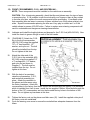
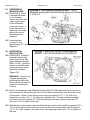
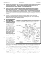
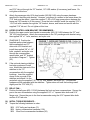
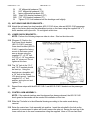
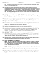
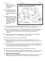
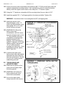
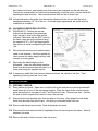
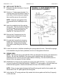
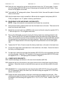
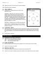
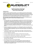
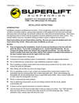
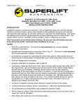
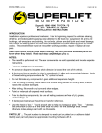
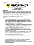
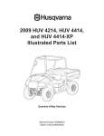
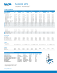
FORM #3145.03-110209 PRINTED IN U.S.A. PAGE 1 OF 23 Superlift 6” lift system for 1995- 2003 CHEVROLET S-10 BLAZER / PICKUP 4WD without ZR2 option package INSTALLATION INSTRUCTIONS INTRODUCTION Installation requires a professional mechanic. Prior to beginning, inspect the vehicles steering, driveline, and brake systems, paying close attention to the suspension link arms and bushings, anti-sway bars and bushings, tie rod ends, pitman arm, ball joints and wheel bearings. Also check the steering sector-to-frame and all suspension-to-frame attaching points for stress cracks. The overall vehicle must be in excellent working condition; repair or replace all worn parts. Read instructions several times before starting. Be sure you have all needed parts and know where they install. Read each step completely as you go. NOTES: • This kit fits only the standard S-10 Blazer / Pickup in the years specified. It will not fit vehicles equipped with the ZR2 option package. • Welding is required. • A special tool is required to load/unload the torsion bars (step 3). Other special tools are recommended to detach/attach the pitman/idler studs. Refer to the factory service manual. • Front end realignment is necessary. • An arrow on diagrams indicates which direction is toward the front of the vehicle. • A foot-pound torque reading is given in parenthesis ( ) after each appropriate fastener. • Do not fabricate any components to gain additional suspension height. • Prior to drilling or cutting, check behind the surface being worked on for any wires, lines, or hoses that could be damaged. • After drilling, file smooth any burrs and sharp edges. • Prior to operating a torch or saw, protect any heat-sensitive components located in the immediate area by covering them with a water-saturated cloth. Most undercoatings are flammable but can be extinguished using a water-filled spray bottle. Have a spray bottle and an ABC rated fire extinguisher on hand. • Paint or undercoat all exposed metal surfaces. • Prior to attaching components, be sure all mating surfaces are free of grit, grease, undercoating, etc. • A factory service manual should be on hand for reference. • Use the check-off box “” found at each step to help you keep your place. Two “” denotes that one check-off box is for the driver side and one is for the passenger side. Unless otherwise noted, always start with the driver side. FORM #3145.03-110209 PRINTED IN U.S.A. PAGE 2 OF 23 PARTS LIST … The part number is stamped into each part or printed on an adhesive label. Identify each part and place the appropriate mounting hardware with it. PART NO DESCRIPTION NEW ATTACHING HARDWARE (Qty.- if more than one) (Qty.- if more than one) 55-01-3140................... differential drop bracket, .............. (2) bushing half upper, driver side (1) 3/4” OD x 2-3/8” sleeve 55-02-3140................... differential drop bracket, .............. (1) 1/2” x 1-1/2” bolt passenger side (3) 1/2” x 1-1/4” bolt (4) 1/2” USS washer (4) 1/2” nyloc nut 55-03-3140................... centerlink ..................................... (4) 1/8” x 1-1/2” cotter pin 55-04-3140................... C.S.S. link.................................... (4) bushing half (2) 3/4” OD x 1-3/4” sleeve (1) 1/2” x 3” carriage bolt (1) 1/2” x 3” bolt (2) 1/2” SAE washer (2) 1/2” nyloc nut (2) 3/16” knock-in zerk fitting 55-05-3140 .................. front crossmember....................... (2) 14mm x 110mm socket head bolt (2) 14mm lock nut (2) 10mm x 20mm bolt (2) 3/8” SAE flat washer (1) 9/16” x 3-1/2” bolt (5) 9/16” SAE washer (1) 9/16” nyloc nut 55-06-3140 .................. rear crossmember ....................... (2) 14mm x 100 mm bolt (2) 14mm lock nut (4) 9/16” SAE flat washer (2) 1” OD x 2” sleeve 55-07-3140 .................. upper control arm drop ................ (2) 12mm x 100mm bolt bracket, driver side (2) 12mm lock nut (2) special square washer (1) 7/16” x 1-1/4” bolt (1) 7/16” flat washer (1) 7/16” tab nut (2) 3/8” x 1” bolt (2) 3/8” USS washer (2) 3/8” nyloc nut (3) 1/2” USS washer (1) 9/16” USS washer (1) 1-1/2” OD x 2-1/4” sleeve (1) zip tie (1) cotter pin FORM #3145.03-110209 PART NO PRINTED IN U.S.A. PAGE 3 OF 23 DESCRIPTION NEW ATTACHING HARDWARE (Qty.- if more than one) (Qty.- if more than one) 55-08-3140 ................. upper control arm drop ................. (2) 12mm x 100mm bolt bracket, passenger side (2) 12mm lock nut (2) special square washer (1) 7/16” x 1-3/4” bolt (1) 7/16” flat washer (1) 7/16” tab nut (2) 3/8” x 1” bolt (2) 3/8” USS washer (2) 3/8” nyloc nut (2) 1/2” USS washer (1) 9/16” USS washer (1) 1” OD x 5/8” sleeve (1) 1-1/2” OD x 2-1/4” sleeve (1) zip tie (1) cotter pin 55-10-3140 ................. upper control arm bracket ............ (2) 3/8” x 1” bolt crossmember (2) 3/8” x 1-1/4” bolt (4) 3/8” SAE washer (4) 3/8” nyloc nut (1) spacer plate 55-11-3140 ................. belly pan ....................................... (8) 5/16” x 1” tapered allen bolt (4) 5/16” flange nut (2) 5/16” tab nut 55-39-3140 .................. torsion bar drop bracket ............... (8) 3/8” x 1” self tapping bolt driver side (2) 1/2” x 3” bolt (2) 1/2” USS washer (2) 1/2” stover nut (2) 2" OD x 3/16" thick washer (2) stainless steel badge (4) 1/8” x 1/2” aluminum rivets 55-40-3140 .................. torsion bar drop bracket ............... (8) 3/8” x 1” self tapping bolt passenger side (2) 1/2” x 3” bolt (2) 1/2” USS washer (2) 1/2” stover nut (2) 2" OD x 3/16" thick washer (2) stainless steel badge (4) 1/8” x 1/2” aluminum rivets 55-19-3140-1 .............. lower front shock bracket, ............ (1) 1/2” x 2-1/2” bolt front, driver side (1) 1/2” x 2-1/4” bolt (2) 1/2” stover nut (1) 3/4” x 1-1/4” sleeve (1) 1/4” x 1” bolt (1) 1/4” SAE washer (1) 1/4” nyloc nut (1) shock mount spacer FORM #3145.03-110209 PART NO PRINTED IN U.S.A. PAGE 4 OF 23 DESCRIPTION NEW ATTACHING HARDWARE (Qty.- if more than one) (Qty.- if more than one) 55-13-3140................... frame reinforcement plate 55-19-3140-2 ............... lower front shock bracket, rear, driver side 55-20-3140-1 ............... lower front shock bracket,............ (1) 1/2” x 2-1/2” bolt front, passenger side (1) 1/2” x 2-1/4” bolt (2) 1/2” stover nut (1) 3/4” x 1-1/4” sleeve (1) 1/4” x 1” bolt (1) 1/4” SAE washer (1) 1/4” nyloc nut (1) shock mount spacer 55-20-3140-2 ............... lower front shock bracket, rear, passenger side 55-21-3140 .................. anti-sway bar drop bracket, ......... (2) 3/8” x 1” bolt front, driver side (4) USS flat washer (2) 3/8” nyloc nut 55-22-3140 .................. anti-sway bar drop bracket, ......... (2) 3/8” x 1” bolt front, passenger side (4) USS flat washer (2) 3/8” nyloc nut 55-28-3120................... (2) brake line bracket, front.......... (4) 1/4” x 1-1/4” bolt (8) 1/4” flat washer (4) 1/4” nyloc nut 45-3120 ....................... (2) brake line extensions, front, 3/8” fittings (1995-1997) 46-3120 ........................ (2) brake line extensions, front, 7/16” fittings (1998-2001) 47-3120 ........................ (2) 3/8” female / female adapter 48-3120 ........................ (2) 7/16” female / female adapter differential vacuum solenoid ........ (2) 5/16” x 1” self-tapping bolt relocation hardware (3) zip tie 55-23-3140 .................. (2) rear spring pad bracket 55-24-3140 .................. (2) rear U-bolt plate 55-30-3140 .................. rear brake hose junction block keeper FORM #3145.03-110209 PART NO PRINTED IN U.S.A. PAGE 5 OF 23 DESCRIPTION NEW ATTACHING HARDWARE (Qty.- if more than one) (Qty.- if more than one) 55-23-3120 ................. lower shock bracket, .................... (1) 7/16” x 3-1/4” x 4-1/2” U-bolt driver side, rear (2) 7/16” SAE washer (2) 7/16” nyloc nut (1) 1/2” x 2-3/4” bolt (1) 1/2” SAE washer (1) 1/2” nyloc nut 55-24-3120 ................. lower shock bracket, .................... (1) 7/16” x 3-1/4” x 4-1/2” U-bolt passenger side, rear (2) 7/16” SAE washer (2) 7/16” nyloc nut (1) 1/2” x 2-3/4” bolt (1) 1/2” SAE washer (1) 1/2” nyloc nut 55-21-7055 ................. emergency brake cable ................ (1) 5/16” x 1” bolt extension bracket (2) 5/16” USS washer (1) 5/16” nyloc nut 55-35-3120 ................. (2) rear brake line bracket ............ (2) 5/16” x 1” self-tapping bolt 89400 .......................... rear brake hose ............................ (1) 5/16” x 1” bolt (1) 5/16” nyloc nut 85070........................... (2) shock absorber, front .............. (2) hardware pack and cable tie 85140........................... (2) shock absorber, rear ............... (2) hardware pack and cable tie 0034............................. Superlift badge ............................. alcohol wipe pad 00461........................... decal, "Warning To Driver" FRONT DISASSEMBLY 1) PREPARE VEHICLE... Place vehicle in neutral. Raise front of vehicle with a jack and secure a jack stand beneath each frame rail, behind the lower control arms. Ease the frame down onto the stands, place transmission in low gear or “park”, and chock rear tires. Remove front tires. 2) REMOVE BATTERY… NOTE: The battery and battery tray must be removed in order to access the vacuum solenoid for the front differential, which is relocated in a later step. Open the hood and remove the positive and negative cables from the battery. Remove the clamp holding the battery in place and lift the battery out of the vehicle. Save all hardware for reuse. Loosen the two bolts holding the battery tray in place and remove the tray. Save all hardware for reuse. FORM #3145.03-110209 PRINTED IN U.S.A. PAGE 6 OF 23 Locate the vacuum solenoid that actuates the front differential. Carefully disconnect the cable from the solenoid as well as its mounting bracket and remove the screws holding the solenoid and bracket to the inner fenderwell. Save all components and hardware for reuse. 3) UNLOADING THE TORSION BARS… WARNING: Be extremely careful when loading and unloading the torsion bars; there is a tremendous amount of energy stored in them. Keep your hands and body clear of the adjuster arm assembly and the puller tool in case anything slips or breaks. Mark the torsion bars to indicate their indexing in relation to the lower control arms and the adjuster arms. A special torsion bar puller tool is required to unload the torsion bars (refer to Diagram 11). Use the tool to load the torsion bar, then remove the adjusting bolt and nut block. Unload the bar, slide the adjuster arms out of the crossmember, then slide the torsion bars forward (into the lower control arms). NOTE: Because of the extreme loads generated by the torsion bars on these vehicles, a standard two-jaw puller tool tends to bend the "lips" of the crossmember (which it uses for attachment) and may pop out of place. We have had the best results using a C-clamp type puller tool. If one cannot be found locally, this tool (PN J-22517-C) is available from the Kent Moore Tool Group in Roseville, Michigan (800/345-2233 or 313/774-9500). 4) TORSION BAR CROSSMEMBER… Remove the two bolts that attach the crossmember to the frame and set the crossmember aside. Slide the torsion bars out of the lower control arms and save for reuse. 5) BRAKE CALIPERS… Unclip the brake hose from the upper control arm. Remove the two bolts securing the caliper assembly to the knuckle. Leave the brake hose attached to the caliper, and using mechanic’s wire, hang the calipers out of the way. Take precautions to ensure the brake hose isn’t stretched or pinched. Unplug the ABS wire from the connector located at the top of the frame rail and unclip the wire from the upper control arm. 6) SWAY BAR… Loosen the threaded rod inside the sway bar end links and remove the bushings, rod, and tube. Set these parts aside. Unbolt the sway bar from the frame and retain all factory hardware. 7) TIE RODS… Remove the cotter pins (if applicable) and nuts securing the tie rod to the centerlink and to the knuckle. Using a tie rod separating tool, separate the ends from the centerlink and knuckle. Set these components aside for re-use. 8) CONTROL ARM / HUB ASSEMBLY… FORM #3145.03-110209 PRINTED IN U.S.A. PAGE 7 OF 23 NOTE: Many installers prefer to remove the control arms, knuckle, and CV shaft as one large assembly in order to save the extra time it takes to separate the upper ball joint and CV shaft from the knuckle. This can be done with the help of an assistant and a jack. If there is no help available, removing the components individually is recommended. NOTE: Perform the following steps one side at a time. Start on the driver side. Remove and discard the front shocks. Loosen and remove the nut securing the CV axle to the hub assembly. A special tool is recommended to separate the upper ball joint from the knuckle. Support the control arm assembly with a jack and remove the cotter pin (if applicable) and castle nut from the upper ball joint stud. Using the special tool, separate the upper ball joint from the knuckle. Take precautions to avoid damaging the rubber dust boot, as it will be reused. NOTE: If a ball joint tool is not available, the ball joint can be separated from the knuckle by firmly hitting the side upper portion of the knuckle with a hammer. Be careful not to damage any other components. Loosen the cam bolts that attach the upper control arm to the frame, and slide the UCA out of the frame brackets. Set the UCA aside, and save all hardware for reuse. With the help of an assistant, remove the bolts that hold the lower control arm to the frame, slide the LCA and knuckle assembly away from the vehicle to separate the CV shaft from the knuckle, then carefully lower the assembly to the floor. Slide each CV axle out of the differential. Use rags to plug the holes in the differential to avoid loosing any differential fluid. Mark which side each shaft came from for reassembly. 9) COMPRESSION STOPS AND CENTERLINK… Loosen and remove the nut holding the compression travel stop cup to the frame. Save all components for re-use. Remove the nuts on the pitman and idler arms, and using the appropriate puller tool, remove the factory centerlink assembly. Retain all the factory hardware. 10) DIFFERENTIAL… Disconnect the electrical plug and breather tube from the differential. Snake the actuator cable (disconnected in step 2) out and away from all other undercarriage components so that the cable will not interfere with differential removal. Position a jack underneath the differential housing and place just enough pressure on the jack to support the differential’s weight. Unbolt the driveshaft from the differential yoke and tie the driveshaft out of the way. Retain all the factory hardware. Remove and discard the factory rear crossmember. FORM #3145.03-110209 PRINTED IN U.S.A. PAGE 8 OF 23 Remove the driver side lower differential bolt and the two differential bolts on the passenger side, followed by driver side upper differential bolt. Carefully lower the differential to the floor. Save the driver side lower differential bolt for reuse. FRONT ASSEMBLY 11) TRIMMING THE FRAME… [DIAGRAM 1] Temporarily install the front crossmember (#55-06-3140) and loosely attach it to the factory front lower control arm mounts as shown. Using the crossmember as a template, mark the area on the frame to be trimmed flush with the crossmember (do not remove the welded portion of the frame). Remove the crossmember and use a torch or plasma cutter to trim off the marked areas. [DIAGRAM 1] Remove the extension stops from the frame brackets for the upper control arms. Grind any rough areas smooth and paint any exposed metal surfaces. Temporarily install the centerlink (#55-033140) on the pitman and idler arms and cycle the steering lock-to-lock in order to check for adequate clearance between the centerlink and the frame. Additional trimming may be necessary to gain adequate clearance. [DIAGRAM 2] Following the cut lines shown, remove the driver side lower differential mount located on the frame mount for the lower control arm’s rear leg. Test fit the supplied reinforcement plate (#55-13-3140) as shown. It may be necessary to trim the plate slightly to ensure a proper fit. Once the frame and plate are properly prepped for later welding, tack weld the reinforcement bracket in place. Do not completely weld the reinforcement plate at this time. The differential must be test-fit first, and final welding will occur in a later step. FORM #3145.03-110209 PRINTED IN U.S.A. PAGE 9 OF 23 12) FRONT CROSSMEMBER, C.S.S., AND CENTERLINK… NOTE: These components must be installed on the vehicle as an assembly. CAUTION: Prior to beginning assembly, check the idler and pitman arms for signs of wear or excessive play. If it is possible to spin the studs with your fingers or there is play evident in the idler pivot arm, replace the worn components before proceeding. It has been noted that excessive idler arm wear is common on these vehicles even if they show relatively low miles. Superlift recommends replacing the idler arm if any play is evident and / or if the vehicle shows in excess of 50,000 miles. Failure to replace worn steering components will result in undesirable and dangerous steering characteristics. Lubricate and install the bushing halves and sleeves for the C.S.S. link (#55-04-3140). Also install the knock-in grease fittings in each of the link’s ends. [DIAGRAM 3] Attach the C.S.S. link to the front crossmember (#55-05-3140) using the supplied 1/2” x 3” hex-head bolt, 1/2” washer, and nyloc nut. The bolt should be installed from the top. Do not tighten at this time. Attach the other end of the C.S.S. link to the centerlink (#5503-3140) using the supplied 1/2” x 3” carriage bolt, 1/2” washer, and nyloc nut as shown in Diagram 3. The bolt must be installed from the top. Do not tighten at this time. With the help of an assistant raise the crossmember, C.S.S., and centerlink assembly into place. Attach the centerlink to the pitman and idler arms using the factory hardware. Attach the crossmember to the factory front lower control arm mounts using the factory LCA hardware, which is installed from front-to-rear. Install the two supplied 10mm x 20mm bolts through the bottom of the “05” crossmember and into the threaded factory holes in the bottom of the frame. Do not tighten any hardware at this time. Tighten the factory nuts on the pitman and idler arms (45). Install the supplied cotter pins if the factory nuts are castellated. Cycle the steering once more to ensure the centerlink has adequate clearance from the frame. FORM #3145.03-110209 PRINTED IN U.S.A. PAGE 10 OF 23 13) DIFFERENTIAL MODIFICATIONS… [DIAGRAM 4] Using a portable band saw or cut-off wheel, remove the driver side upper mounting ear on the differential housing as shown. It is also necessary to slightly trim the metal plate on the side of the differential as indicated. Using the same cutting tool, trim approximately 1/4” off of the ribbing on the driver side of the differential as indicated in Diagram 4. 14) DIFFERENTIAL INSTALLATION… [DIAGRAM 5] Install the supplied bushings and sleeve in the driver side upper differential bracket (#55-01-3140). Install the bracket on the differential housing as shown using the factory hardware. Tighten (35). WARNING: Failure to use a torque wrench when tightening the differential housing bolts may result in warping or cracking the housing. Position the passenger side differential bracket (#55-02-3140) against the factory mount on the frame with the tall end facing the front of the vehicle and the open side facing the center of the vehicle. Attach it to the factory mount using the supplied 1/2” x 1-1/2” bolt in the forward hole and the 1/2” x 1-1/4” bolt in the rearward hole. The bolts should be installed front the top and the supplied 1/2” USS flat washers should be positioned under the 1/2” nyloc nuts. Do not tighten at this time. With the help of an assistant raise the differential into position and install the supplied 9/16” x 3-1/2” bolt through the driver side front mount (at the front crossmember) and the supplied 1/2” x 1-1/4” bolts, washers, and nyloc nuts on the passenger side mount. Do not tighten at this time. FORM #3145.03-110209 PRINTED IN U.S.A. PAGE 11 OF 23 Raise the rear crossmember (#55-06-3140) into position and loosely secure using the factory lower control arm hardware. Secure the driver side lower differential mount to the “06” crossmember using the factory hardware. Do not tighten at this time. Check to see if there is adequate clearance between the differential housing (where the ribbing was removed) and the “13” reinforcement plate that is currently tack-welded into place. If there is a sufficient amount of clearance, remove the crossmember and differential housing in order to finish welding the reinforcement plate. If there is not sufficient clearance, trim the position of the reinforcement plate and test-fit once again until adequate clearance is achieved. Once the “13” reinforcement plate has been completely welded, cooled, and painted, reinstall the differential and rear crossmember by repeating this step. Do not tighten any hardware at this time unless otherwise specified. 15) UPPER CONTROL ARM DROP BRACKETS… [DIAGRAM 6] Attach the driver side upper control arm drop bracket (#5507-3140) to the factory front UCA mount as shown using the supplied 12mm x 100mm bolts, square washers, 9/16” USS washers, and 12mm lock nuts. Note that the square washers should be positioned in the original control arm cam bolt slots. Do not tighten at this time. Attach the “07” bracket to the rear UCA frame mount using the supplied 12mm x 100mm bolt, washers, and 12mm lock nut. The bolt should be installed front the rear. Note that the supplied 1-1/2” OD x 2-1/4” long crush sleeve should be positioned in the void of the frame bracket (where the UCA used to be mounted) and that a 9/16” USS washer should be positioned in the recess between the “07” bracket and the rear face of the UCA frame mount as indicated in Diagram 6. Do not tighten at this time. Locate the 7/16” diameter hole in the “07” bracket roughly below the factory front UCA frame mount. Using the bracket as a template, drill a 7/16” hole in the vehicle’s frame as shown in Diagram 6. Note that due to a variance in vehicle frames, it may be necessary to insert a 1/2” USS washer between the “07” bracket and the frame where the hole was drilled in order for the bracket to sit properly on the frame. Install the supplied 7/16” x 1-1/4” bolt, washer FORM #3145.03-110209 PRINTED IN U.S.A. PAGE 12 OF 23 and 7/16” tab nut through the “07” bracket, 1/2” USS washer (if necessary) and frame. Do not tighten at this time. Attach the passenger side UCA drop bracket (#55-08-3140) using the same hardware specified for the driver side bracket. However, note there is a recess in the frame where the 7/16” hole must be drilled. Insert the supplied 1” OD x 5/8” long spacer sleeve between the frame and “08” bracket to fill this recess. Once the hole is drilled, install the supplied 7/16” x 1-3/4” bolt with a washer through the “08” bracket, sleeve, and frame and secure with the supplied 7/16” tab nut. Do not tighten at this time. 16) UPPER CONTROL ARM BRACKET CROSSMEMBER… Position the upper control arm bracket crossmember (#55-10-3140) between the “07” and “08” UCA drop brackets. Attach the crossmember to the “08” passenger side bracket using the supplied 3/8” x 1” bolts, washers, and nyloc nuts. [DIAGRAM 7] Position the supplied spacer plate between the crossmember and “07” driver side UCA bracket and install the supplied 3/8” x 1-1/4” bolts, washers, and nyloc nuts through the crossmember, spacer plate, and “07” bracket as shown in Diagram 7. Tighten (23). If the optional steering stabilizer has been purchased, install now. Attach the stem end of the stabilizer to the “10” crossmember with the supplied bushings. Insert the supplied sleeve in the eye end of the stabilizer and attach it to the centerlink using the supplied 7/16” x 2-1/2” bolt, washer, and nyloc nut. The stabilizer hardware will be packaged with the stabilizer. Tighten stem end until the bushings swell slightly and the 7/16” bolt (37). 17) BELLY PAN… Position the belly pan (#55-11-3140) between the front and rear crossmembers. Secure the pan to the rear crossmember using the supplied 5/16” x 1” tapered allen bolts and 5/16” flange nuts. Secure the pan to the front crossmember using the 5/16” tapered allen bolts and two 5/16” tab nuts. 18) INITIAL TORQUE SEQUENCE… Torque the following hardware in order: 5/16” belly pan hardware (13) factory crossmember hardware (109) 10mm front crossmember hardware (25) FORM #3145.03-110209 PRINTED IN U.S.A. PAGE 13 OF 23 1/2” differential hardware (70) 9/16” differential hardware (114) factory differential hardware (65) 12mm UCA bracket hardware (107) 7/16” UCA bracket hardware (37) Tighten C.S.S. link hardware until the bushings swell slightly. 19) ANTI-SWAY BAR DROP BRACKETS… Attach the anti-sway bar drop brackets (#55-21-3140 driver side and #55-22-3140 passenger side) to the factory anti-sway bar attachment points on the frame using the supplied 3/8” x 1” bolts, washers, and nyloc nuts. Do not tighten at this time. 20) LOWER SHOCK BRACKETS… NOTE: Perform the following steps one side at a time. Start on the driver side. [Diagram 8] Position the front lower shock bracket (#55-19-3140-1) and rear lower shock bracket (#55-193140-2 ) against the factory mount on the lower control arm as shown using the supplied 1/2” x 2-1/2” bolt, 3/4” OD x 1-1/4” long sleeve, and 1/2” stover nut. Do not tighten at this time. The 1/4” hole in the “19-1” and “19-2” brackets should be lined up. Using the brackets as a template, drill a 1/4” hole in the factory LCA shock mount. Insert the supplied 1/4” x 1” bolt, washer, and nyloc nut and tighten (13). Repeat these steps with the #55-20-3140-1 and #55-20-3140-2 brackets on the passenger side. 21) CONTROL ARM ASSEMBLY… NOTE: If the optional stainless steel brushguard has been purchased, the #55-16-3140 brush guard crossmember will be needed for installation at this time. Slide the CV shafts in to the differential housing according to the marks made during removal. Raise the control arm / hub assembly into position. Insert the axle shaft in the hub as the assembly is maneuvered in place and loosely secure the axle nut. Secure the rear leg of the lower control arm to the rear crossmember using the supplied 14mm x 100 mm hex head FORM #3145.03-110209 PRINTED IN U.S.A. PAGE 14 OF 23 bolt. The bolt should be installed from the front. Loosely secure using the supplied 14mm nut, but do not tighten at this time. If installing the optional stainless steel brush guard, line up the brush guard mounting crossmember (#55-16-3140) with the mounting holes for the lower control arms on the front crossmember. Install the supplied 14mm x 110mm socket head bolt through the “16” brush guard crossmember, “21” or “22” anti-sway bar brackets, crossmember, and lower control arm. The bolt should be installed from the front. Loosely secure using the supplied 14mm nut, but do not tighten at this time. Attach the upper control arm to the “07” or “08” UCA drop bracket using the factory cam bolts. Rotate the cams so that the alignment pins are centered in the cam bolt slots. Snug, but do not fully tighten at this time. Raise the control arm / hub assembly and reattach the upper ball joint to the knuckle using the factory hardware. Tighten (37). Install a new cotter pin (supplied) if equipped. Tighten the axle shaft nut (133). Connect the tie rods to the centerlink and knuckle, secure using the factory hardware, and tighten (44). Install new cotter pins (supplied) if equipped. Install the bushings and sleeves in the front shock absorbers (#85070). Attach the body of the shock to the lower shock mount using the supplied 1/2” x 2-1/4” bolt and stover nut. Secure the rod end of the shock to the upper mount using the factory hardware. Tighten the lower 1/2” hardware (70) and the factory upper bolt (57). 22) ANTI-SWAY BAR… Attach the anti-sway bar to the anti-sway bar drop brackets (#55-15-3120 driver side and #55-16-3120 passenger side) using the supplied 3/8” x 1” bolts, washers, and nyloc nuts. Tighten the lower and upper sway bar bracket hardware (33). Attach the factory anti-sway bar links to the ends of the bar, then connect the links to the to the lower control arms and tighten until the bushings swell slightly. 23) FRONT BRAKE HOSE EXTENSIONS… NOTE: Two sets of brake line extensions are included in the kit box. One set is equipped with 3/8” flare fittings (45-3120) for 1994-1997 models and the other set is equipped with 7/16” fittings (46-3120) for 1998-2003 models. Verify that you have the correct extensions for your application before continuing. NOTE: The following steps should be performed one side at a time. Start on the driver side. Detach the rubber brake hose from the metal line. Plug both ends to minimize fluid loss. [Diagram 9] Loosely install the rotor and caliper assembly on the knuckle using the factory hardware. Route the brake hose under the upper control arm but above the CV axle as shown. FORM #3145.03-110209 PRINTED IN U.S.A. PAGE 15 OF 23 NOTE: Using a line wrench is recommended for all brake line connections. Unclip the brake line from the bracket securing it to the side of the frame and unbolt the bracket from the frame. Attach a brake line bracket (#55-28-3120) to the frame in the same location as the factory bracket that was just removed and as shown in Diagram 9. Use the factory hardware and tighten (10). Install the appropriate female / female adapter fitting (#47-3120 or #48-3120) on one end of each brake line extension (#45-3120 or #46-3120). Tighten using a line wrench. Connect the female end of the “45” or “46” brake line extension to the metal brake line at the frame. Verify that the rubber brake hose is still routed under the upper control arm, then connect the male end of the extension to the rubber brake hose and tighten both connections. Secure the factory brake line support bracket to the “28” bracket as shown in Diagram 9 using the supplied 1/4” x 1-1/4” bolts, washers, and nyloc nuts (9). Tighten the caliper assembly to factory specifications. Unclip the ABS connector located at the top of the frame. Mark and drill a 1/4” hole approximately mid-way down the side of the frame directly below where the connector was originally located. Reroute the connector to the side of the frame and secure it in the hole drilled in the previous step. If needed, additional slack can be gained by unwrapping a section of the ABS wires from the rest of the wire loom in the engine compartment. Route the ABS wire as shown in Diagram 9, then reattach it to the connector. Secure both the factory brake hose and ABS wire guide brackets to the front leg of the upper control arm and secure using the supplied 1/4” x 1-1/4” bolt, washer, and nyloc nut (9). 24) TORSION BAR DROP BRACKETS… NOTE: If the vehicle is equipped with the ZR5 appearance package you must remove the step bar brackets located on the frame rail outside the torsion bar mounting location. FORM #3145.03-110209 PRINTED IN U.S.A. PAGE 16 OF 23 Position the torsion bar crossmember drop brackets (#55-17-3140) on the frame under the original crossmember mounting location. Use a plumb bob or level to locate the bracket directly under the original mount location, then clamp the “17” bracket in place.. Using the “17” bracket as a template, drill the mounting holes (four per side) to 5/16”. Install the supplied 3/8” x 1” self-tapping bolts in the holes just drilled. Tighten (24). WARNING: Use extreme care to not overtighten the 3/8” self-tapping bolts. Install the stainless steel Superlift badges on the “17” torsion bar drop brackets using the supplied 1/8” x 1/2” rivets and an ordinary rivet gun. [DIAGRAM 10] Mount the factory torsion bar crossmember, with the torsion bar holes facing forward, to the “17” drop brackets using the combination of bushings and hardware detailed in the Diagram. Note that there is a special 2” diameter x 3/16” thick washer supplied, and that the 1/2” x 3” bolts should be installed from the bottom. Once assembled as shown, tighten the 1/2” bolt (76). Lubricate both ends of the factory torsion bars with grease, then slide the torsion bars into the lower control arms. Be sure to line up the indexing marks made during removal. 25) TORSION BARS AND ADJUSTER ARMS… Clean the hex splines on the torsion bar and apply a light lubricating grease. [DIAGRAM 11] Position the factory adjuster arm in the torsion bar crossmember. Line up the marks made during removal for the torsion FORM #3145.03-110209 PRINTED IN U.S.A. PAGE 17 OF 23 bar, lower control arm, and adjuster arm, then torsion bar rearward into the adjuster arm. Position the special puller tool used during disassembly. Load the puller / bar and install the adjusting bolt and nut block. Use extreme caution while the bar is under load. Unload and remove the puller, then thread the adjuster bolt into the nut until the arm is raised approximately 1/4" off of the nut. Final ride height adjustments are made after the installation is complete. 26) VACUUM SOLENOID RELOCATION… [DIAGRAM 12] Position the vacuum solenoid on the inside of the passenger frame rail just in front of the idler arm as indicated. Mark and drill two 9/32” holes in the frame, then secure the solenoid using the supplied 5/16” x 3/4” self-tapping bolts. Use caution to avoid overtightening the bolts (10). Reconnect the vacuum hose and actuating cable to the solenoid. Use the supplied zip ties to secure the cable away from any heat sources or moving parts. Reconnect the electrical plug to the differential. Unclip the differential breather hose from the fan shroud and relocate it to a lower point using the supplied zip ties. If necessary, install the front tires and wheels and lower the vehicle to the floor. Final tightening of the lug nuts will occur later. REAR PROCEDURE 27) PREPARE VEHICLE... Place vehicle in neutral. Raise rear of vehicle with a jack and secure a jack stand beneath each frame rail, in front of the rear spring hangers. Ease the frame down onto the stands, place transmission in low gear or “park”, and chock front tires. Remove rear tires. Position the jack so that it supports, but does not raise, the rear axle. Disconnect the axle breather tube from the axle or the frame. Also detach the rear brake hose from the metal line at the frame. Use a plug to minimize brake fluid loss. Remove and discard rear shocks. Save all hardware for reuse. Disconnect the anti-sway bar links (if applicable) from the bar body and the frame. Save all hardware for reuse. Remove the axle U-bolts, but save them for re-use. FORM #3145.03-110209 PRINTED IN U.S.A. PAGE 18 OF 23 28) INSTALLING TIE BOLTS… Raise the rear axle and secure it up and out of the way. Position a C-clamp approximately 3- to 4-inches away from the center tie bolt on each side to hold the leaf pack together, then carefully remove the center bolt. NOTE: Verify the spring pack is fully compressed before installing the new bolt. Insert the supplied tie-bolt through the spring pack. The bolt should be installed so that the head is at the bottom of the spring pack. Install and tighten the supplied 3/8” fine-thread nut (23). Remove the C-clamps and trim the excess length of the tie-bolt using a hacksaw or cutoff wheel. On each side, loosen the front spring hanger bolt and remove the spring-toshackle bolt. Swing the leaf springs down and let them hang from the front hanger. Lower the rear axle to facilitate reinstalling the springs above the axle. Reinstall the springs in the shackles using the factory hardware, but do not fully tighten at this time. 29) SPRING PADS… NOTE: The Superlift spring pads (#55-29-3120) are indexed off the factory pads attached to the axle. Be sure the underside of the factory pads (opposite where the springs were attached) are free from dirt and other debris before continuing. Also be sure the areas on the axle tubes are prepped for later welding. [DIAGRAM 13] Examine the supplied rear spring pads (#55-23-3140). You will note that one end of each pad is taller than another. Index the “23” spring pads on the axle tubes and inside the factory pads so that the tall end faces the rear of the vehicle as shown. NOTE: If there is extra space between the Superlift spring pads and the factory pads, butt the tall end of the “23” pads against the factory pads. Verify that the “29” spring pads are fully seated in the factory pads and that they fit properly on the axle tube. FORM #3145.03-110209 PRINTED IN U.S.A. PAGE 19 OF 23 Raise the rear axle and line up the tie bolts with the holes in the “23” spring pads. Position the U-bolt plates (#55-36-3120) on top of the springs and reinstall the stock U-bolts. Snug, but do not fully tighten at this time. Tack-weld the “29” spring pads in place. Remove the U-bolts, then weld the pads to the axle tubes on both sides. After the welds have cooled, reinstall the U-Bolts with the supplied U-bolt plates (#55-243140), and tighten in an “X” pattern to factory specifications. 30) REAR BRAKE HOSE AND BRAKE LINE BRACKETS… NOTE: Using a line wrench is recommended on all brake line connections. Disconnect the factory rubber brake hose from the brake lines on the axle. Then remove the hose from the axle and discard. Attach the new rear brake hose (#89400) to the mount on the axle using the supplied 5/16” x 1” bolt and nyloc nut. Do not tighten at this time. Remove the differential cover bolt securing the factory brake hose retaining bracket to the axle. Position the #55-30-3140 brake line keeper so that the brake hose fitting (where the rubber hose meets the junction block) is between the forked end of the bracket (this prevents the junction block from swiveling on the factory bracket). Secure both the factory bracket and the “30” keeper bracket to the axle using the factory differential cover bolt and tighten (23). Tighten the 5/16” bolt (13) and connect the factory brake lines on the axle to the brake hose. Connect the upper end of the brake hose to the metal line on the frame. Secure the hose to the factory mounting bracket. On each side, attach the rear brake line brackets (#55-35-3120) to the metal brake lines that run along the axle. Attach the “35” brackets to the rear spring perches (#55-29-3120) using the supplied 5/16” x 1” self-tapping bolts as shown in Diagram 1. 31) LOWER SHOCK BRACKETS… Install the bushings and stickers on the rear shock absorbers (#85140). Attach the rod end of the shocks to the upper shock mounts on the frame using the factory hardware. Extend the shocks so that the bottom eyes are even with the middle of the axle tube. [DIAGRAM 13] Loosely attach the lower shock bracket (#55-23-3120 driver side and #5524-3120 passenger side) to the lower eye of the shock using the supplied 1/2” x 2-3/4” bolt, washer, and nyloc nut. Rotate the lower shock bracket so that the curved edge rests against the axle tube. After verifying once again that the lower shock eye is even with the middle of the axle tube, secure the bracket to the tube using the supplied 7/16” x 3-1/4” x 4-1/2” U-bolt , washers, and 7/16” nuts (41). FORM #3145.03-110209 PRINTED IN U.S.A. PAGE 20 OF 23 Tighten the upper (27) and lower (57) shock hardware. Reinstall the tires and wheels. 32) TIRES / WHEELS... [DIAGRAM 14] Tighten the lug nuts (102) in the sequence shown. WARNING: When the tires / wheels are installed, always check for and remove any corrosion, dirt, or foreign material on the wheel mounting surface, or anything that contacts the wheel mounting surface (hub, rotor, etc.). Installing wheels without the proper metalto-metal contact at the wheel mounting surfaces can cause the lug nuts to loosen and the wheel to come off while the vehicle is in motion. WARNING: Retighten lug nuts at 500 miles after any wheel change, or anytime the lug nuts are loosened. Failure to do so could cause wheels to come off while vehicle is in motion. 33) CLEARANCE CHECK... With the vehicle still on jack stands, and the suspension “hanging” at full extension travel, cycle steering lock-to-lock and check all components for proper operation and clearances. Pay special attention to the clearance between the tires / wheels and brake hoses, wiring, etc. Lower vehicle to the floor. FINAL PROCEDURES 34) HARDWARE TIGHTENING SEQUENCE… Tighten the following hardware in sequence: Lower control arm hardware (82). Rear spring hardware (148). 35) BLEED THE BRAKES… Bleed the brake system following the procedure found in the factory service manual. Inspect all connections for leaks. 36) REINSTALL BATTERY… Reinstall the battery tray and secure using the factory hardware (23). Install and reconnect the battery using the procedure found in the factory service manual. FORM #3145.03-110209 PRINTED IN U.S.A. PAGE 21 OF 23 37) TURNING RADIUS STOPS… NOTE: Some deeply inset wheels, when turned full lock, may make slight contact with the upper control arm. Even if the wheels are not making contact, the close clearance may interfere with wheel balancing weights. If either problem exists, perform this step. In some cases it may be necessary to abandon knock-on weights in favor of tape-ons. Locate the factory turning radius stops on the rear of the lower control arms and prep the area for welding. [DIAGRAM 15] Weld the furnished 3/8" O.D. x 1" long piece of half-section tubing onto both factory turning radius stops as shown. After the area has cooled, paint the exposed surfaces. 38) ADJUSTING FRONT RIDE HEIGHT... Manually bounce the front and rear of vehicle to normalize the torsion bars and leaf springs. [DIAGRAM 15] Position the vehicle on a level surface. Measure from the LCA front pivot bolt center down to the floor. Record this as Measurement “A”. Now measure from the inside edge of the knuckle (at the lower ball joint boss) down to the floor. Record this as Measurement “B”. Subtract measurement “B” from “A” for the ride height figure. Minimum ride height is 4.6”; maximum is 5.2”. Preferred ride height is 4.9”. Raise height by tightening the torsion bar adjusting bolt; lower height by loosening the bolt. Adjust height 3/8” to 1/2” above the final desired ride height, since the bars will settle slightly after the vehicle is driven. NOTE: Exceeding the stated minimum or maximum heights will cause the suspension to continually “top out” or “bottom out”. This results in a harsh ride, accelerated suspension component wear, and possibly component failure. FORM #3145.03-110209 PRINTED IN U.S.A. PAGE 22 OF 23 39) FINAL CLEARANCE and TORQUE CHECK... With vehicle on floor, cycle steering lock-to-lock and inspect the tires / wheels, and the steering, suspension, and brake systems for proper operation, tightness, and adequate clearance. 40) Activate four wheel drive system and check front hubs for engagement 41) HEADLIGHTS... Readjust headlights to proper setting. 42) SUPERLIFT WARNING DECAL... Install the WARNING TO DRIVER decal on the inside of the windshield, or on the dash, within driver’s view. Refer to the “NOTICE TO DEALER AND VEHICLE OWNER” section below. 43) ALIGNMENT... Realign vehicle to factory specifications. Record the ride height measurement at time of alignment. If, in the future the torsion bars settle excessively, alignment can be restored by adjusting-up the bars to their original ride height. Limited Lifetime Warranty / Warnings ® Your Superlift product is covered by the Limited Warranty explained below that gives you specific legal rights. This ® ® limited warranty is the only warranty Superlift makes in connection with your product purchase. Superlift neither assumes nor authorizes any retailer or other person or entity to assume for it any other obligation or liability in connection with this product or limited warranty. ® What is covered? Subject to the terms below, Superlift will repair or replace its products found defective in materials or workmanship for so long as the original purchaser owns the vehicle on which the product was originally ® ® installed. Your warrantor is LKI Enterprises, Inc. d/b/a Superlift Suspension Systems (“Superlift ”). ® What is not covered? Your Superlift Limited Warranty does not cover products, parts or vehicles Superlift® determines to have been damaged by or subjected to: • Alteration, modification or failure to maintain. • Normal wear and tear (bushings, tie-rod ends, etc.). Scratches or defects in product finishes (powdercoating, plating, etc.), • Damage to or resulting from vehicle’s electronic stability system, related components or other vehicle systems. • Racing or other vehicle competitions or contests. Accidents, impact by rocks, trees, obstacles or other aspects of the environment. • Theft, vandalism or other intentional damage. Remedy Limited to Repair / Replacement. The exclusive remedy provided hereunder shall, upon Superlift’s inspection and at Superlift’s option, be either repair or replacement of product or parts covered under this Limited ® Warranty. Customers requesting warranty consideration should contact Superlift by phone (1-800-551-4955) to obtain a Returned Goods Authorization number. All removal, shipping and installation costs are customer’s responsibility. ® If a replacement part is needed before the Superlift part in question can be returned, you must first purchase the replacement part. Then, if the part in question is deemed warrantable, you will be credited / refunded. Other Limitations - Exclusion of Damages - Your Rights Under State Law ® ® • Neither Superlift nor your independent Superlift dealer are responsible for any time loss, rental costs, FORM #3145.03-110209 PRINTED IN U.S.A. PAGE 23 OF 23 or for any incidental, consequential or other damages you may have. • This Limited Warranty gives you specific rights. You may also have other rights that vary from state to state. For example, while all implied warranties are disclaimed herein, any implied warranty required by law is limited to the terms of our Limited Lifetime Warranty as described above. Some states do not allow limitations of how long an implied warranty lasts and / or do not allow the exclusion or limitation of incidental or consequential damages, so the limitations and exclusions herein may not apply to you. Important Product Use and Safety Information / Warnings As a general rule, the taller a vehicle is, the easier it will roll over. Offset, as much as possible, what is lost in rollover resistance by increasing tire track width. In other words, go “wide” as you go “tall”. Many sportsmen remove their mud tires after hunting season and install ones more appropriate for street driving; always use as wide a tire and wheel combination as feasible to enhance vehicle stability. We strongly recommend, because of rollover possibility, that the vehicle be equipped with a functional roll bar and cage system. Seat belts and shoulder harnesses should be worn at all times. Avoid situations where a side rollover may occur. Generally, braking performance and capabilities are decreased when significantly larger / heavier tires and wheels are used. Take this into consideration while driving. Also, changing axle gear ratios or using tires that are taller or shorter than factory height will cause an erroneous speedometer reading. On vehicles equipped with an electronic speedometer, the speed signal impacts other important functions as well. Speedometer recalibration for both mechanical and electronic types is highly recommended. Do not add, alter, or fabricate any factory or aftermarket parts to increase vehicle height over the intended height of the Superlift product purchased. Mixing component brands is not recommended. ® ® All Superlift material is copyrighted. All images found in this catalog and in any Superlift marketing forums are the ® sole property of or licensed to Superlift . Any reproduction of said materials, in part or in whole, with out the express ® ® written permission of Superlift is strictly forbidden. Superlift , Rockrunner™, Swamprunner™, Superide™, Superide ® SS™ and SSR™, Black Diamond , XCL™, X2™ Super Trac™, Torque Max™, Torque Max SS™, eXtreme Ring™, Rail Wrap™, Bullet Proof Brake Hose™, TruSpeed™, Frame Integrated Technology™, F.I.T. Series™ and Rock ™ ® ® Fink are registered trademarks of Superlift Suspension Systems. Superlift Suspension Systems is a Division of Bret Lovett’s Lift Kits Incorporated. SUPERLIFT SUSPENSION SYSTEMS 300 Huey Lenard Loop Rd. West Monroe, Louisiana 71292 Phone: (318) 397-3000 Sales / Tech: 1-800-551-4955 FAX: (318) 397-3040 www.superlift.com