1
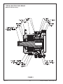
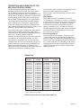
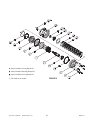
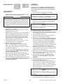
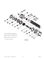
MULTIPLE
DISC BRAKE
(liquid cooled - SAE C size)
Service Manual
MICO could not possibly know of and give advice with respect to all conceivable applications in which this product may be used and the possible hazards and/or
results of each application. MICO has not undertaken any such wide evaluation. Therefore, anyone who uses an application which is not recommended by the
manufacturer, first must completely satisfy himself that a danger will not be created by the application selected, or by the particular model of our product that is
selected for the application.
MICO has made every attempt to present accurate information in catalogs, brochures and other printed material. MICO can accept no responsibility for errors
from unintentional oversights that may exist. Due to a continuous program of product improvement, materials, specifications, and product documentation are
subject to change without notice or obligation.
MICO is a registered trademark of MICO, Inc. MICO is registered in the U.S. Patent and Trademark Office as well as in Australia, Canada, Indonesia, Japan, Peoples Republic of China, South Korea, and the European Community.
MICO, Incorporated
Innovative Braking and Controls Worldwide
Form No. 81-540-007
Revised 1997-11-01
1911 Lee Boulevard / North Mankato, MN U.S.A. 56003-2507
Tel: +1 507 625 6426 Fax: +1 507 625 3212
www.mico.com
TYPICAL MULTIPLE DISC BRAKE
(Model 02-540-060 shown)
FIGURE 1
MICO, Inc.
(2)
Form No. 81-540-007
Revised 1997-11-01
DESCRIPTION AND OPERATION OF THE
MICO MULTIPLE DISC BRAKE
of the brake will start to initiate a brake application. Zero
pressure produces maximum brake torque.
Brake cooling is normally provided by one of the following methods:
The MICO Multiple Disc Brake (liquid cooled) is
designed specifically for use with heavy duty machinery, off-highway vehicles, construction, materials
handling, mining equipment and in a multitude of winching applications. Models are available in standard SAE
mounting flange styles. Other special mountings are
also available. Contact MICO with your requirements.
Sump Method
Oil is added at the time of installation to a level of
1/4-1/2 capacity, 118.3-236.6 mL (4-8 fl oz). A breather
must be installed on the top cooling port to compensate
for expansion, due to heat. This method of cooling is
used where the operation of the brake is strictly for
parking or emergency use, i.e. either on or off with
minimal dragging through the brake. Also the maximum
shaft speed must not exceed 1500 rpm in this mode
due to fluid viscous shear.
This multiple disc brake provides consistent braking
torque, positive hold, and long life in rugged environments. An oil bath protects the friction surfaces, dissipates heat efficiently and resists internal corrosion, thus
providing high repeatability in performance.
The brake will also reduce maintenance and downtime,
because environmental contaminants which add to
brake lining wear are restricted from entering the brake.
Clean oil is a must for optimum lining life.
Braking is provided by a pack of friction discs splined to
the housing, and rotating discs splined to the drive
shaft. Force is transmitted to the disc pack through a
hydraulic piston and a series of preloaded springs. The
brake is released by hydraulic pressure applied to the
piston to compress the springs. The brake is selfapplying since any function which reduces the hydraulic
system pressure below the release pressure
Flow Through Method
A continuous flow of oil between 3.79 and 30.3 L/min
(1 and 8 GPM) from the vehicles hydraulic system is
used for cooling. This method is required where the application may involve dragging through the brake such
as in a winch application for positioning a load. Internal
cooling pressure should be maintained below 6.9 bar
(100 PSI). This method is also ideal for higher shaft
speed applications.
Repair Kits
Model
Number
Lining Kit
Number
Bearing Kit
Number
02-540-050
02-540-052
02-540-054
02-540-056
02-540-060
02-540-062
02-540-064
02-540-066
02-540-068
02-540-070
02-540-072
02-540-074
02-540-076
02-540-078
02-540-200
02-540-204
02-540-206
02-540-208
02-540-210
20-060-040
20-060-040
20-060-040
20-060-040
20-060-040
20-060-040
20-060-040
20-060-040
20-060-040
20-060-040
20-060-040
20-060-047
20-060-046
20-060-040
20-060-046
20-060-040
20-060-040
20-060-040
20-060-040
02-500-062
02-500-062
02-500-062
02-500-062
02-500-062
02-500-062
02-500-062
02-500-062
02-500-062
02-500-070
02-500-062
02-500-083
02-500-081
02-500-070
02-500-081
02-500-070
02-500-062
02-500-062
02-500-062
O-ring Kit
Number
* 02-500-061
02-500-064
02-500-063
02-500-064
* 02-500-061
02-500-064
02-500-063
02-500-064
02-500-087
02-500-069
02-500-063
02-500-082
02-500-080
02-500-069
02-500-080
02-500-069
02-500-105
02-500-087
02-500-063
* Same kit as 02-500-064 with the addition of seal (17) and retaining ring (19).
All kits include mounting gasket.
NOTE: Earlier models do not use spacer plate (15).
Form No. 81-540-007
Revised 1997-11-01
(3)
MICO, Inc.
Model Numbers: 02-540-050
02-540-052
02-540-056
02-540-060
02-540-062
02-540-066
02-540-068
02-540-074
02-540-076
02-540-200
02-540-206
02-540-208
ASSEMBLY
(Refer to Figure 2)
LUBRICATE ALL RUBBER COMPONENTS FROM
REPAIR KIT WITH CLEAN TYPE FLUID USED IN
THE SYSTEM. REFER TO PAGE 3 FOR PROPER
REPAIR KIT.
1. Clean all parts thoroughly before assembly.
DISASSEMBLY
NOTE
(Refer to Figure 2)
Follow step 2 only if seal (17) and retaining ring (19)
are found in your brake during disassembly.
1. Remove end cover (3) from housing (18) by removing cap screws (1) and lock washers (2).
2. Insert new retaining ring (19) in housing (18). Press
new seal (17) into housing (18) until it shoulders
against retaining ring (19).
Since cover is under spring tension of approximately
907 kgf (2000 lb), the six cap screws must be loosened evenly to relieve this force. If a hydraulic press is
available, 2268 kgf (5000 lb maximum), the cover can
be held in position while removing the cap screws and
lock washers.
NOTE
Follow step 3 only if spacer plate (15) was found in
your brake during disassembly.
3. Insert spacer plate (15) in housing (18).
4. Starting with one of nine new steel plates (13) and
alternating with eight of the ten new friction plates
(14), install them on shaft (6).
5. Install new bearing (16) on male end of shaft (6)
and press until it shoulders on shaft.
6. Insert one of two remaining new friction plates (14)
in housing (18). With shaft (6) positioned vertically
(male end facing down), place shaft assembly in
housing (18) aligning tabs with slots in housing.
Carefully press shaft assembly into housing (18)
until bearing shoulders on bottom of housing. Insert
the last new friction plate (14) in housing (18).
7. Install new o-rings (9 & 11) and new back-up rings
(8 & 12) on piston (10). Carefully push piston (10)
into bore of housing (18) until piston bottoms on top
of lining stack.
8. Insert springs (7) in piston (10). NOTE: Install
springs (7) in same pattern as they were removed.
9. Press new bearing (5) in end cover (3). Install new
o-ring (4) on flange of cover (3).
10. Position cover assembly on top of springs (7). Insert cap screws (1) and lock washers (2) through
cover (3) and into housing (18). Tighten screws
evenly to draw cover (3) to housing (18) and bearing (5) onto shaft (6). Torque cap screws (1)
74.6 N·m (55 lb·ft).
2. If necessary, tap cover with a soft mallet to dislodge
bearing (5) from shaft (6).
3. Remove o-ring (4) from flange of cover (3). Press
bearing (5) out of cover (3).
4. Remove springs (7) from piston (10). Remove piston (10) from housing (18) by inserting two
1/2-13 UNC bolts into threaded holes at bottom of
spring pockets in piston (10). Using appropriate
puller, remove piston (10) from bore of housing.
Note quantity and pattern of springs (7) when
removed.
5. Remove o-ring (9), back-up ring (8), o-ring (11) and
back-up ring (12) from piston (10).
6. Remove shaft assembly consisting of shaft (6),
plates (13), friction plates (14) and bearing (16)
from housing (18) by pressing or using a soft mallet
on male end of shaft (6).
7. Remove spacer plate (15) and bottom friction plate
(14) from housing (18). NOTE: Earlier models do
not use spacer plate (15).
8. Remove bearing (16) from end of shaft (6) with
appropriate bearing puller. Remove steel plates
(13) and friction plates (14) from male end of shaft
(6).
9. Remove retaining ring (19) and press seal (17) from
housing (18). NOTE: Not all models use seal (17)
and retaining ring (19).
NOTE
A hydraulic press will simplify installation of cover on
housing. Clamp cover in position while tightening the
cap screws.
11. To eliminate binding on bearings, press on inner
ring of bearing (5) until it shoulders on shaft (6).
MICO, Inc.
(4)
Form No. 81-540-007
1997-11-01
s Items included in Lining Repair Kit
l
Items included in Bearing Repair Kit
n
Items included in O-ring Repair Kit
*
Not used on all models
Form No. 81-540-007
Revised 1997-11-01
FIGURE 2
(5)
MICO, Inc.
Model Numbers: 02-540-054
02-540-064
02-540-070
02-540-072
02-540-078
02-540-204
02-540-210
ASSEMBLY
(Refer to Figure 3)
LUBRICATE ALL RUBBER COMPONENTS FROM
REPAIR KIT WITH CLEAN TYPE FLUID USED IN
THE SYSTEM. REFER TO PAGE 3 FOR PROPER
REPAIR KIT.
DISASSEMBLY
1. Clean all parts thoroughly before assembly.
(Refer to Figure 3)
1. Remove end cover (3) from housing (18) by removing cap screws (1) and lock washers (2).
NOTE
Follow step 2 only if seal (17) and retaining ring (19)
are found in your brake during disassembly.
Since cover is under spring tension of approximately
907 kgf (2000 lb), the six cap screws must be loosened evenly to relieve this force. If a hydraulic press is
available, 2268 kgf (5000 lb maximum), the cover can
be held in position while removing the cap screws and
lock washers.
2. Insert new retaining ring (19) in housing (18). Press
new seal (17) into housing (18) until it shoulders
against retaining ring (19).
NOTE
Follow step 3 only if spacer plate (15) was found in
your brake during disassembly.
2. If necessary tap cover with a soft mallet to dislodge
bearing (5) from shaft (6).
3. Remove o-ring (4) from flange of cover (3). Press
bearing (5) out of cover (3).
4. Remove springs (7) from piston (9). Remove piston
(9) from housing (18) by inserting two 1/2-13 UNC
bolts into threaded holes at bottom of spring pockets in piston (9). Using appropriate puller, remove
piston (9) from bore of housing. Note quantity and
pattern of springs (7) when removed.
5. Use appropriate puller to remove sleeve (11). Remove o-rings (10 & 12) from sleeve (11).
6. Remove o-ring (8) from piston (9).
7. Remove shaft assembly consisting of shaft (6),
plates (13), friction plates (14) and bearing (16)
from housing (18) by pressing or using a soft mallet
on male end of shaft (6).
8. Remove spacer plate (15) and bottom friction plate
(14) from housing (18). NOTE: Earlier models do
not use spacer plate (15).
9. Remove bearing (16) from end of shaft (6) with
appropriate bearing puller. Remove plates (13) and
friction plates (14) from male end of shaft (6).
10. Remove retaining ring (19) and press seal (17) from
housing (18). NOTE: Not all models use seal (17)
and retaining ring (19).
3. Insert spacer plate (15) in housing (18).
4. Starting with one of nine new steel plates (13) and
alternating with eight of the ten new friction plates
(14), install them on shaft (6).
5. Install new bearing (16) on male end of shaft (6)
and press until it shoulders on shaft.
6. Insert one of two remaining new friction plates (14)
in housing (18). With shaft (6) positioned vertically
(male end facing down), place shaft assembly in
housing (18) aligning tabs with slots in housing.
Carefully press shaft assembly into housing (18)
until bearing shoulders on bottom of housing. Insert
the last new friction plate (14) in housing (18).
7. Install new o-rings (10 & 12) on sleeve (11). Carefully push sleeve (11) into bore of housing (18) until
piston bottoms on housing bore.
8. Install new o-ring (8) on piston (9). Carefully push
piston (9) into bore of housing (18) until piston bottoms on top of lining stack.
9. Insert springs (7) in piston (9). NOTE: Install
springs (7) in the same pattern as they were
removed.
10. Press new bearing (5) in end cover (3). Install new
o-ring (4) on flange of cover (3).
11. Position cover assembly on top of springs (7). Insert cap screws (1) and lock washers (2) through
cover (3) and into housing (18). Tighten screws
evenly to draw cover (3) to housing (18) and bearing (5) onto shaft (6). Torque cap screws (1)
74.6 N·m (55 lb·ft).
NOTE
A hydraulic press will simplify installation of cover on
housing. Clamp cover in position while tightening the
cap screws.
12. To eliminate binding on bearings, press on inner
ring of bearing (5) until it shoulders on shaft (6).
MICO, Inc.
(6)
Form No. 81-540-007
Revised 1997-11-01
s Items included in Lining Repair Kit
l
Items included in Bearing Repair Kit
n
Items included in O-ring Repair Kit
*
Not used on all models
Form No. 81-540-007
FIGURE 3
Revised 1997-11-01
(7)
MICO, Inc.
BLEEDING
1. Install brake in system and connect pressure lines as well as
coolant lines if flow through
cooling is used.
2. Bleed pressure release section
of brake by pressurizing side
inlet port and allowing air to
escape from top port. Pressure
should not exceed 6.9 bar
(100 PSI) during bleeding.
3. Apply sufficient pressure to
release brake and check for
proper operation in system.
SERVICE DIAGNOSIS
(Refer to Figure 2)
BRAKE WILL NOT RELEASE
1. Insufficient release oil pressure
2. Damaged o-rings (9 or 11)
3. Damaged o-ring (12), Figure 3
4. Damaged piston (10), Figure 2
5. Damaged bearings (5 or 16)
6. Plates (13 & 14) warped or
welded together due to excessive heat
MICO, Inc.
BRAKE WILL NOT APPLY
1. Residual oil pressure in release
section of brake
2. Damaged springs (7)
3. Damaged piston (10), Figure 2
4. Broken bolts (1) allowing cover
(3) to move away from housing
(18)
(8)
BRAKE APPLIES BUT TORQUE
LOW
1. Residual oil pressure in release
section of brake
2. Springs (7) have taken permanent set due to excessive heat
3. Friction plates (14) worn out
OIL LEAKS EXTERNALLY FROM
BRAKE
1. Damaged rotary oil seal (17)
2. Damaged o-ring (4)
Form No. 81-540-007
Revised 1997-11-01