1
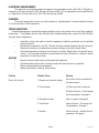
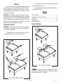
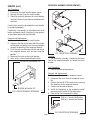
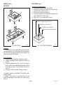
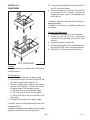
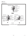
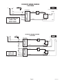
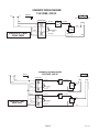
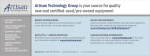
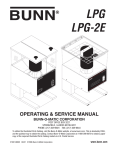
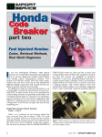
1SH & 2SH
STAND
OPERATING & SERVICE MANUAL
BUNN-O-MATIC CORPORATION
POST OFFICE BOX 3227
SPRINGFIELD, ILLINOIS 62708-3227
PHONE: (217) 529-6601 FAX: (217) 529-6644
To obtain the Illustrated Parts Catalog, visit the Bunn-O-Matic website, at www.bunn.com. This is absolutely FREE,
and the quickest way to obtain the catalog. Contact Bunn-O-Matic Corporation at 1-800-286-6070 to obtain a paper
copy of the required Illustrated Parts Catalog mailed via U.S. Postal Service.
28342.0000F 06/07 ©1997 Bunn-O-Matic Corporation
www.bunn.com
WARRANTY
Bunn-O-Matic Corp. (“Bunn”) warrants the equipment manufactured by it to be commercially free from defects in material and workmanship existing at the time of manufacture and appearing within one year from the
date of installation. In addition:
1.) Bunn warrants electronic circuit and/or control boards to be commercially free from defects in material
and workmanship for two years from the date of installation.
2.) Bunn warrants the compressor on refrigeration equipment to be commercially free from defects in material and workmanship for two years from the date of installation.
3.) Bunn warrants that the grinding burrs on coffee grinding equipment will grind coffee to meet original
factory screen sieve analysis for three years from date of installation or for 30,000 pounds of coffee, whichever
comes first.
This warranty does not apply to any equipment, component or part that was not manufactured by Bunn or
that, in Bunn’s judgement, has been affected by misuse, neglect, alteration, improper installation or operation,
improper maintenance or repair, damage or casualty.
THE FOREGOING WARRANTY IS EXCLUSIVE AND IS IN LIEU OF ANY OTHER WARRANTY, WRITTEN OR
ORAL, EXPRESS OR IMPLIED, INCLUDING, BUT NOT LIMITED TO, ANY IMPLIED WARRANTY OF EITHER
MERCHANTABILITY OR FITNESS FOR A PARTICULAR PURPOSE. The agents, dealers or employees of Bunn
are not authorized to make modifications to this warranty or to make additional warranties that are binding on
Bunn. Accordingly, statements by such individuals, whether oral or written, do not constitute warranties and
should not be relied upon.
The Buyer shall give Bunn prompt notice of any claim to be made under this warranty by telephone at (217)
529-6601 or by writing to Post Office Box 3227, Springfield, Illinois, 62708-3227. If requested by Bunn, the
Buyer shall ship the defective equipment prepaid to an authorized Bunn service location. If Bunn determines, in
its sole discretion, that the equipment does not conform to the warranty, Bunn shall repair the equipment with no
charge for parts during the warranty period and no charge for labor by a Bunn Authorized Service Representative
during the warranty period. If Bunn determines that repair is not feasible, Bunn shall, at its sole option, replace
the equipment or refund the purchase price for the equipment.
THE BUYER’S REMEDY AGAINST BUNN FOR THE BREACH OF ANY OBLIGATION ARISING OUT OF THE
SALE OF THIS EQUIPMENT, WHETHER DERIVED FROM WARRANTY OR OTHERWISE, SHALL BE LIMITED, AS
SPECIFIED HEREIN, TO REPAIR OR, AT BUNN’S SOLE OPTION, REPLACEMENT OR REFUND.
In no event shall Bunn be liable for any other damage or loss, including, but not limited to, lost profits, lost
sales, loss of use of equipment, claims of Buyer’s customers, cost of capital, cost of down time, cost of substitute
equipment, facilities or services, or any other special, incidental or consequential damages.
USER NOTICES
The notice on the stands should be kept in good condition. Replace if unreadable or damaged.
00986.0000
Page 28342 071599
ELECTRICAL REQUIREMENTS
The stands have an attached cordset and requires 2-wire grounded service rated 100V or 120 volts ac,
single phase, 90 watts total for the 1SH, 180 watts total for the 2SH, or 2-wire grounded service rated 230 volts
ac, single phase, 90 watts total for the 1SH, 180 watts total for the 2SH.
CLEANING
The use of a damp cloth rinsed in any mild, nonabrasive, liquid detergent is recommended for cleaning
all surfaces on Bunn-O-Matic equipment.
TROUBLESHOOTING
A troubleshooting guide is provided to suggest probable causes and remedies for the most likely problems
encountered. If the problem remains after exhausting the troubleshooting steps, contact the Bunn-O-Matic
Technical Service Department.
•
•
•
WARNING
•
•
•
•
Inspection, testing, and repair of electrical equipment should be performed only by qualified
service personnel.
All electronic components have 120 - 240 volt ac and low voltage dc potential on their terminals.
Shorting of terminals or the application of external voltages may result in board failure.
Intermittent operation of electronic circuit boards is unlikely. Board failure will normally be permanent. If an intermittent condition is encountered, the cause will likely be a contact or a loose
connection at a terminal or crimp.
Exercise extreme caution when servicing electrical equipment.
Disconnect power source when servicing, except when electrical tests are specified.
Follow recommended service procedures.
Replace all protective shields or safety notices.
Problem
Probable Cause
Remedy
Server will not heat
1. No power or incorrect voltage.
Be sure the stand is connected to
the power source.
2. Circuit breaker
A) Check and reset if necessary
B) Refer to Service - Circuit breaker
for test procedures. See page 4
3. Receptacle contact
Clean or replace. See page 5
4. Transformer
Refer to Service - Transformer for
test procedures. See page 7
5. Rectifier
Refer to Service - Rectifier for test
procedures. See page 6
Page 28342 061807
SERVICE
This section provides procedures for testing and
replacing various major components used in these
stands should service become necessary. Refer to
Troubleshooting for assistance in determining the
cause of any problem.
WARNING - Inspection, testing, and repair of electrical equipment should be performed only by qualified
service personnel. The stands should be unplugged
when servicing, except when electrical tests are required and the test procedure specifically states to
connect the stand to the power source.
COMPONENT ACCESS
The receptacle cover is attached with four #6-32
truss head locking screws.
The stand cover is attached with four #6-32 truss
head locking screws.
Contents
Circuit Breaker......................................................... 4
Receptacle (Spring Contacts)................................... 5
Rectifier................................................................... 6
Transformer............................................................. 7
Wiring Diagrams...................................................... 9
CIRCUIT BREAKER
WARNING - Disconnect the stand from the power
source before the removal of any panel or the replacement of any component.
All components are accessible by the removal
of the receptacle cover and the stand cover.
FIG. 2 CIRCUIT BREAKER
P1402
Location
The circuit breaker(s) is located on the upper
part of the receptacle bracket just above the spring
contact receptacle(s) assembly.
FIG. 1 COMPONENT ACCESS
P1402
Page 28342 091597
SERVICE (cont.)
RECEPTACLE ASSEMBLY (SPRING CONTACT)
Test Procedures
1. Disconnect the stand from the power source.
2. Remove the wires from the circuit breaker.
3. Check for continuity between the circuit breaker
terminals. Continuity must be present between the
terminals.
If continuity is present as described the circuit breaker
is functioning properly.
If continuity is not present as described, press reset
button and repeat step #3, if continuity is not present
as described, replace the circuit breaker.
Removal and Replacement:
1. Remove the wires from the circuit breaker.
2. Compress the clips on the back side of the receptacle bracket and gently push the circuit breaker
through the opening in the receptacle bracket.
3. Push the new circuit breaker into the opening in
the receptacle bracket until the clips snap into
position.
4. Reconnect the wires to the circuit breaker.
5. Refer to Fig. 3 when reconnecting the wires.
BLU/BLK to Transformer #12
FIG. 4 RECEPTACLE ASSEMBLY
P1402
Location:
The receptacle assembly is located on the lower
front of the receptacle bracket just below the circuit
breaker.
Test Procedures:
1. Clean or replace spring contacts.
BLU/BLK to Rectifier "AC"
FIG. 3 CIRCUIT BREAKER TERMINALS
P1330
Removal and Replacement:
1. Disconnect the stand from the power source.
2. Disconnect the wires from the receptacle assembly.
3. Remove the two #6-32 flat head screws securing
the receptacle to the receptacle bracket.
4. Remove and discard receptacle.
5. Install new receptacle in the receptacle bracket
and secure with two #6-32 flat head screws..
6. Refer to Fig. 5 and reconnect the wires.
BLK to (-) Terminal on Rectifier
RED to (+) Terminal on Rectifier
Page FIG. 5 RECEPTACLE TERMINALS
P1380
28342 091597
SERVICE (cont.)
RECTIFIER
RECTIFIERS (cont.)
Removal and Replacement:
1 Disconnect the wires from the rectifier.
2. Remove the #6-32 truss head screw securing the
rectifier to the stand housing.
3. Remove the rectifier and discard.
4. Install new rectifier in the stand housing and secure
with a #6-32 truss head screw.
5. Refer to Fig 7 and reconnect the wires.
RED to Right Receptacle Terminal
BLU/BLK to Transformer #7
BLU/BLK to Circuit Breaker
BLK to Left Receptacle Terminal
+
C
A
C
A
FIG. 6 RECTIFIER
FIG. 7 RECTIFIER TERMINALS
P1403.40
P1381
Location:
The rectifier(s) is located inside on the right side of
the stand housing just to the right of the transformer
for 1SH Stand and on the right and left side of the
stand housing for 2SH Stand.
Test Procedures:
1. Disconnect the stand from the power source.
2. Remove the red wire and the black wire from the
rectifier.
3. Check the voltage across the (+) and (-) terminals
on the rectifier with a voltmeter. Connect the stand
to the power source. The indication must be 24
volts dc.
4. Disconnect the stand from the power source.
If voltage is present as described, the rectifier is operating properly.
If voltage is not present as described, refer to the
stand wiring diagrams and check the stand wiring
harness.
Page 28342 061598
SERVICE (cont.)
TRANSFORMER
5. Disconnet the blue/black wires from terminals #7
and #12 on the transformer.
6. Check the voltage across terminal #7 and #12 of
the transformer with a voltmeter. Connect the
stand to the power source. The indication must
be 24 volts ac.
If voltage is present as described the transformer is
operating properly.
If voltage is not present as described, replace the
transformer.
Removal and Replacement:
1. Disconnect all the wires from the transformer.
2. Remove the four #6-32 screws securing the
transformer and mounting strap to the stand
housing.
3. Remove transformer and discard.
4. Install new transformer in the stand housing securing with four #6-32 screws and mounting strap.
5. Refer to Fig. 9 when reconnecting the wires.
FIG. 8 TRANSFORMER
P1403.40
Location:
The transformer(s) is located in the stand housing
on the base plate.
Test Procedures:
1. Disconnect the stand from the power source.
2. Disconnect the black wire from terminal #5 and
the white or red wire from terminal # 6.
3. Check the voltage across the black and white or
red wire with a voltmeter. Connect the stand to
the power supply. The indication must be:
a.) 100 volts ac for two wire 100 volt models.
b.) 120 volts ac for two wire 120 volt models.
c.) 200 to 240 volts ac for two wire 200 or 240
volt models.
4. Disconnect the stand from the power supply.
If voltage is present as described reconnect the wires
and proceed to #5.
If voltage is not present as described, refer to the wiring
diagrams and check the stand wiring harness.
Page 28342 061807
SERVICE (cont.)
TRANSFORMER (cont.)
#6 WHI or RED from
Transformer Terminal #2
6
#12 BLU/BLK to
Circuit Breaker
#5 BLK From Transformer
Terminal #1
1
2
3
4
5
#7BLU/BLK to Rectifier
Terminal "AC"
#2 WHI or RED From
Power Supply Connection
#1 BLK From Power
Supply Connection
1SH STAND
#6 WHI or RED from
Transformer Terminal #2
#1 BLK From Power
Supply Connection
#1 BLK from Transformer
Terminal #5
LEFT
#12 BLU/BLK to
Right Circuit Breaker
3
4
5
6
#7 BLU/BLK to Right
Rectifier "AC"
#2 WHI or RED to
Transformer Terminal #6
2
#12 BLU/BLK to Left
#5 BLK from
Circuit Breaker
Transformer
#5 BLK to Right
Transformer Terminal #1 Terminal #1
#2 WHI or Red
#7 BLU/BLK to Left
From Left
Rectifier "AC"
Transformer
#2 WHI or Red to Right Terminal #2
Transformer Terminal #2
#1 BLK From Right
Transformer Terminal
#5
1
5
4
3
2
1
#6 WHI or RED From
Power Supply Connection
#5 BLK to Transformer
Terminal #1
#2 WHI or RED from
Transformer Terminal #6
6
#6 WHI or Red to
Transformer Terminal #2
#1 BLK to Transformer
Terminal #5
RIGHT
2SH STAND
FIG.9 TRANSFORMER TERMINALS
Page P1404
28342 091597
N
SCHEMATIC WIRING DIAGRAM
1 SH STAND
GRN
L1
BLK
1
WHI
2
TRANSFORMER
12
BLU/BLK
4
AMP
BLU/BLK
24VDC
–
RECT
+
AC
BLU/BLK
7
+
–
AC
6
+
Front view of Server Contacts
5
100 or 120 VOLTS AC
2 WIRE + GND
SINGLE PHASE
–
BLK
BLU/BLK
RED
27789.0000D 02/07 © 1997 BUNN-O-MATIC CORPORATION
N
L1
SCHEMATIC WIRING DIAGRAM
2 SH STAND
GRN
BLK
1
WHI
2
TRANSFORMER
12
7
TRANSFORMER
12
BLU/BLK
BLU/BLK
2
BLK
WHI
BLU/BLK
24VDC
–
–
RECT
+
AC
6
100 or 120 VOLTS AC
2 WIRE + GND
SINGLE PHASE
4
AMP
6
–
RECT
+
AC
7
BLU/BLK
24VDC
–
+
RED
BLU/BLK
AC
5
+
BLK
BLU/BLK
4
AMP
+
Front view of Server Contacts
AC
5
1
BLU/BLK
–
BLU/BLK
BLK
RED
27793.0000C 02/07 © 1997 BUNN-O-MATIC CORPORATION
Page 28342 061807
L2
GRN/YEL
L1
SCHEMATIC WIRING DIAGRAM
1 SH STAND, 230V CE
BRN
1
BLU
2
230 VOLTS AC, 2 WIRE
SINGLE PHASE
TRANSFORMER
–
+
Front view of Server Contacts
12
BLU/BLK
11
BLK
5
8
6
7
4
AMP
BLU/BLK
24VDC
AC
–
RECT
+
AC
RESETTABLE
FUSE
BLU/BLK
+
–
BLK
BLU/BLK
RED
27789.0001D 11/98 © 1997 BUNN-O-MATIC CORPORATION
L2
L1
SCHEMATIC WIRING DIAGRAM
2 SH STAND, 230V CE
GRN/YEL
1
BRN
BLU
BLK
BRN/BLK
230 VOLTS AC, 2 WIRE
SINGLE PHASE
BLK
BLU
TRANSFORMER
12
2
11
5
8
6
7
1
TRANSFORMER
12
2
11
5
8
6
7
BLU/BLK
4
AMP
–
Front view of Server Contacts
BLU/BLK
24VDC
–
AC
–
RECT
+
AC
RESETTABLE
FUSE
4
AMP
BLU/BLK
24VDC
–
+
RED
BLU/BLK
AC
RESETTABLE
FUSE
+
BLK
BLU/BLK
BLU/BLK
BLU/BLK
+
–
RECT
+
AC
BLU/BLK
BLK
RED
27793.0001C 11/98 © 1997 BUNN-O-MATIC CORPORATION
Page 10
28342 071599