1
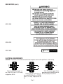
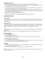
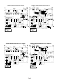
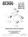
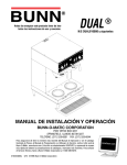
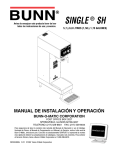
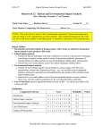
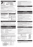
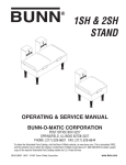
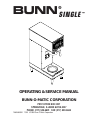
BUNN SINGLE
®
l
l
1 1⁄2
ga
1 ga
l
1⁄2
ga
Y
AD
RE
R
CTO
LE
SE
R
ME
AR
/W
ON
RT
STA
ER
AT
TW
HO
N
IO
UT
!
N
N
RP
CO
TIC .A.
MA U.S
IS,
U
-ONN INO
BU ILL
D,
S/N
BY
ED IEL
UR GF
CT RIN
FA SP
B
NU
TTS
WARTZ
HE S :
NT
TE
P
PA
AM E
G
WIR WIN
LLO
MA
OF
ING
PE
CAUTION
S MA
DE
NT
TE
RE
VE
R
RE
OT
!
IO
UT
MO
ON
N
PA
HE
CO
E OR
LIQUID
ND
Y BE
ON
UN
D
HOT
TH
LTS
RE
VOASE
MO
PH OR
E
R
!
E FO
.
A.C
L
DE
MO
CA
ION
AT
OR
CA
D
ER
NT
CA
DE
AR
SC
DI
IF:
D
Y
KE D
ACTCHEY EMPTE
. CRRA DR N AM IC
D HE FL
. SC ILE W GH ECTR
. BOATED HI D EL
ONSE
. HEED
PO
. US EX TS
RY
. OREMEN
JU
ION
EL
AT
TS
S IN
OR
EN
RP
SK
CO
NT
Y RI MATIC
CO T
-OMPL
EL
NN
NN E HO
CO
5 BU
FU AR
198
E TO
ILUR
FA
: 658
C
A
U
T
IO
N
:
W
A
R
M
E
R
S
A
N
D
S
U
R
F
A
C
E
S
A
R
E
H
O
T
PN
ER
AT
TW
HO
N
IO
UT
!
CA
OPERATING & SERVICE MANUAL
BUNN-O-MATIC CORPORATION
POST OFFICE BOX 3227
SPRINGFIELD, ILLINOIS 62708-3227
PHONE: (217) 529-6601 FAX: (217) 529-6644
10698.0000B 11/93 ©1993 Bunn-O-Matic Corporation
™
INTRODUCTION
This equipment will brew a half-gallon, gallon, or gallon and a half batch of coffee into an awaiting server at
the push of a button and includes a hot water faucet for allied beverage use. The brewer is specifically designed
for use with a BUNN® 1.5GPR server. It is only for indoor use on a sturdy counter or shelf.
WARRANTY
Bunn-O-Matic Corp. (“Bunn”) warrants the equipment manufactured by it to be commercially free from defects
in material and workmanship existing at the time of manufacture and appearing within one year from the date of
installation. This warranty does not apply to any equipment, component or part that was not manufactured by Bunn
or that, in Bunn’s judgement, has been affected by misuse, neglect, alteration, improper installation or operation,
improper maintenance or repair, damage or casualty.
THE FOREGOING WARRANTY IS EXCLUSIVE AND IS IN LIEU OF ANY OTHER WARRANTY, WRITTEN OR
ORAL, EXPRESS OR IMPLIED, INCLUDING, BUT NOT LIMITED TO, ANY IMPLIED WARRANTY OF EITHER
MERCHANTABILITY OR FITNESS FOR A PARTICULAR PURPOSE. The agents, dealers or employees of Bunn are
not authorized to make modifications to this warranty or to make additional warranties that are binding on Bunn.
Accordingly, statements by such individuals, whether oral or written, do not constitute warranties and should not
be relied upon.
The Buyer shall give Bunn prompt notice of any claim to be made under this warranty by telephone at (217)
529-6601 or by writing to Post Office Box 3227, Springfield, Illinois, 62708-3227. If requested by Bunn, the Buyer
shall ship the defective equipment prepaid to an authorized Bunn service location. If Bunn determines, in its sole
discretion, that the equipment does not conform to the warranty, Bunn shall repair the equipment with no charge
for parts during the one year warranty period and no charge for labor for the first 90 days of the warranty period.
If Bunn determines that repair is not feasible, Bunn shall, at its sole option, replace the equipment or refund the
purchase price for the equipment.
THE BUYER’S REMEDY AGAINST BUNN FOR THE BREACH OF ANY OBLIGATION ARISING OUT OF THE SALE
OF THIS EQUIPMENT, WHETHER DERIVED FROM WARRANTY OR OTHERWISE, SHALL BE LIMITED, AS
SPECIFIED HEREIN, TO REPAIR OR, AT BUNN’S SOLE OPTION, REPLACEMENT OR REFUND. Bunn shall not be
liable for any other damage or loss, including, but not limited to, lost profits, lost sales, loss of use of equipment,
claims of Buyer’s customers, cost of capital, cost of down time, cost of substitute equipment, facilities or services,
or any other special, incidental or consequential damages.
USER NOTICES
The notices on this brewer should be kept in good condition. Replace unreadable or damaged labels.
00658.0000
12364.0000
Page 2
USER NOTICES (cont.)
00831.0000
00656.0000
20201.5600
!
CAUTION
HOT WATER
ELECTRICAL REQUIREMENTS
CAUTION - The brewer must be disconnected from the power source until specified in Initial Set-Up.
WHITE
NEUTRAL
L1 BLACK
L2 RED
L2 RED
120V.A.C.
WHITE
120V.A.C.
L1 BLACK
200 OR 240V.A.C.
208 or 240V.A.C.
NEUTRAL
120V.A.C.
L1 BLACK
Requires 2-wire, grounded service rated 120 volts ac, 20 amp,
single phase, 60 Hz.
“A" & "B” models require 2-wire,
grounded service rated 200 volts ac,
Requires 3-wire, grounded ser- 20 amp, single phase, 50 Hz.
vice rated 120/208 volts or 120/240
volts ac, 20 amp, single phase, 60
Hz.
Page 3
Electrical Hook-Up
CAUTION – Improper electrical installation will damage electronic components.
1. An electrician must provide electrical service as specified.
2. Using a voltmeter, check the voltage and color coding of each conductor at the electrical source.
3. Remove the front panel beneath the sprayhead.
Models with electronic control assemblies:
Place the tank heater switch at the top of the control assembly in the “OFF” position.
Models with electromechanical thermostats:
Rotate the control thermostat knob fully counterclockwise to the “OFF” position.
4. Feed the cord through the strain relief and connect it to the terminal block.
5. Connect the brewer to the power source and verify the voltage at the terminal block before proceeding. Replace
the front panel.
6. If plumbing is to be hooked-up later be sure the brewer is disconnected from the power source. If plumbing
has been hooked-up, the brewer is ready for Initial Set-Up.
PLUMBING REQUIREMENTS
This brewer must be connected to a cold water system with operating pressure between 20 and 90 psi from
a 1⁄2" or larger supply line. A shut-off valve should be installed in the line before the brewer. Install a regulator in
the line when pressure is greater than 90 psi to reduce it to 50 psi. The water inlet fitting is 1⁄4" flare.
NOTE – Bunn-O-Matic recommends 1⁄4" copper tubing for installations of less than 25 feet and 3⁄8" for more than
25 feet from the 1⁄2" water supply line. A tight coil of copper tubing in the water line will facilitate moving the brewer
to clean the countertop. Bunn-O-Matic does not recommend the use of a saddle valve to install the brewer. The
size and shape of the hole made in the supply line by this type of device may restrict water flow.
This equipment must be installed to comply with the Basic Plumbing Code of the
Building Officials and Code Administrators International, Inc. (BOCA)
and the Food Service Sanitation Manual of the Food and Drug Administration (FDA).
Plumbing Hook-Up
1. Attach the flare fitting from the short piece of tubing on the flow control (supplied) to the water
inlet fitting on the bottom of the brewer.
2. Flush the water line and securely attach it to the flare fitting on the strainer.
3. Turn on the water supply.
INITIAL SET-UP
CAUTION – The brewer must be disconnected from the power source throughout the initial set-up,
except when specified in the instructions.
1. Remove the front panel beneath the sprayhead.
Models with electronic control assemblies:
Place the tank heater switch at the top of the control assembly in the “OFF” position.
Models with electromechanical thermostats:
Rotate the control thermostat knob fully counterclockwise to the “OFF” position.
2. Connect the brewer to the power source. Water will begin flowing into the tank.
3. When water stops flowing into the tank., remove the front panel and proceed as directed:
Models with electronic control assemblies:
Place the tank heater switch at the top of the control assembly in the “ON” position and replace the front panel.
Models with electromechanical thermostats:
Rotate the control thermostat knob fully clockwise to the “ON” position and replace the front panel.
Page 4
INITIAL SET-UP (cont.)
4. Wait approximately twenty minutes for the water in the tank to heat to the proper temperature.
5. Place an empty server beneath the brew station. Place the Selector switch in the one-gallon position, the On/
Warmer switch in the upper position and initiate a brew cycle.
6. Place the On/Warmer switch in the lower “OFF” position after water has stopped flowing from the funnel, and
check the water volume in the server. It should be 128 ounces.
7. If not, disconnect the brewer from the power source, remove the front panel, and adjust the brew timer dial
up-or-down as required. Replace the front panel, connect the brewer to the power source, allow the water to
reheat, start, and measure another brew cycle.
8. Repeat step 7 until the proper water volume is achieved.
9. The brewer is now ready for use in accordance with the coffee brewing instructions.
OPERATING CONTROLS
Selector Switch
Placing the switch in the 1⁄2 Gal, 1 Gal, or 11⁄2 Gal position selects the amount of coffee to be brewed in
subsequent brew cycles. Repositioning this switch after a brew cycle has been initiated does not change the brew
batch in progress.
On/Warmer Switch
Placing the switch in the unlighted lower position cuts power to the brew station warmer and stops brewing.
Stopping a brew cycle after it has been started will not stop the flow of water from the funnel. Placing the switch
in the lighted upper position supplies power to the brew station warmer and enables the brew circuit.
Start
Momentarily pressing and releasing this switch starts a brew cycle when the On/Warmer switch is in the lighted
upper position.
NOTE – The On/Warmer switch must be in the lighted upper position to initiate and complete a brew cycle.
COFFEE BREWING
1.
2.
3.
4.
5.
6
7.
Select the desired batch size.
Insert a BUNN® filter into the funnel.
Pour the proper amount of fresh coffee into the filter and level the bed of grounds by gently shaking.
Slide the funnel into the funnel rails.
Place an empty server under the funnel.
Place the On/Warmer switch in the lighted upper position. Momentarily press and release the start switch.
When brewing is completed, simply discard the grounds and filter.
CLEANING
1. The use of a damp cloth rinsed in any mild, non-abrasive, liquid detergent is recommended for cleaning all
surfaces on Bunn-O-Matic equipment.
2. Check and clean the sprayhead. The sprayhead holes must always remain open.
NOTE – In hard water areas, this may need to be done daily. It will help prevent liming problems in the brewer and
takes less than a minute.
Page 5
SCHEMATIC WIRING DIAGRAM SINGLE BREWER ECA
SCHEMATIC WIRING DIAGRAM SINGLE BREWER
GRN
L1
L2 N
L1
GRN
TANK HEATER
1800W @120V
3700W @208V
4000W @240V
BLK-12
BLK-12
K1
N.O.
K1
N.O.
VIO
RED
RED
BLK
READY
L.E.D.
BLU
LIQUID 1
LEVEL 2
BOARD 3
4
BLU
BLK
GRY
SOL
WHI
PROBE
PIN 20
(PROBE)
RED (208 OR
WHI (120V)
240V)
GRN
WHI/BLU
1
BREW 2
TIMER 3
4
5
3/4 BATCH
BATCH COMMON
TAN
100W WARMER WHI
WHI/VIO
WHI/VIO
SOL
WHI
WHI
AUXILIARY OUTLET
WHI
WHI/VIO
1/4 BATCH
1/3 BATCH
1/2 BATCH
2/3 BATCH
3
4
5
3/4 BATCH
BATCH COMMON
WHI/VIO
100W WARMER WHI
WHI/VIO
WHI/VIO
WHI
ORA
WHI/GRN
YEL
SOL
WHI/GRN
SOL
WHI/RED
WHI
4
GRY 3 GRINDER
PNK 2 INTERFACE
CONNECTOR
TAN 1
S
W
GREEN
1
BREW 2
TIMER
OPTIONAL WATER
BYPASS SOL.
S
E
L
E
C
T
O
R
WHI/RED
4
GRY 3 GRINDER
PNK 2 INTERFACE
CONNECTOR
TAN 1
GRY
FRACTIONAL
BATCHES
(CONNECT
AS REQUIRED)
FULL BATCH
(NO CONNECTION) PNK
WHI
WHI/ORA
WHI/GRN
WHI/YEL
WHI/GRN
SOL
AUXILIARY OUTLET
WHI
WHI/VIO
GREEN
200 WATT MAXIMUM
200 WATT MAXIMUM
10697.0000D 10/93 © 1993 BUNN-O-MATIC CORPORATION
120 VOLTS AC 2 WIRE
120/208 VOLTS AC OR
120/240 VOLTS AC
3 WIRE
SOL
OPTIONAL 3-SET SELECTOR SWITCH SHOWN
WITH GRINDER INTERFACE OPTION
1/4 BATCH
1/3 BATCH
1/2 BATCH
2/3 BATCH
WHI/VIO
S
W
TAN
BLU
7 WHI/BRN
6
5
4
ELECTRONIC 3
CONTROL 2
1
ASSY
WHI/YEL
ORA
SAFETY SW
RED
RED
BLK
BLK
OPTIONAL WATER
BYPASS SOL.
S
E
L
E
C
T
O
R
PNK
GRY
GRY
GRY
WHI
OPTIONAL 3-SET SELECTOR SWITCH SHOWN
WITH GRINDER INTERFACE OPTION
FRACTIONAL
BATCHES
(CONNECT
AS REQUIRED)
FULL BATCH
(NO CONNECTION) PNK
W
t° H
I
TANK HEATER
SW
PNK
INTERLOCK
ASSY
PIN-20
WHI-12 (208 OR 240V)
WHI -12(120V)
BLU-12
GRY
WHI
K1
BLK
TAN
BLK-12
W
H
I
SW. & THERMOSTAT
SAFETY SW
L2 N
TANK HEATER
1800W @120V
3700W @208V
4000W @240V
RED-12 (208 OR 240V)
WHI-12 (120V)
RED-12
READY INDICATOR
LIMIT THERMOSTAT
BLK
BLK-12
LIMIT
THERMOSTAT
10706.0000B 10/93 © 1993 BUNN-O-MATIC CORPORATION
120 VOLTS AC 2 WIRE
120/208 VOLTS AC OR
120/240 VOLTS AC
3 WIRE
SCHEMATIC WIRING DIAGRAM SINGLE-A & -B BREWER ECA
SCHEMATIC WIRING DIAGRAM SINGLE-A & -B BREWER
GRNYEL
L1
L2
L1
L2
GRN/YEL
TANK HEATER
3700W @200V
3300W @240V
BLK-12
BLK-12
K1
N.O.
VIO
RED
RED
BLK
RED
K1
LIQUID 1
LEVEL 2
BOARD 3
4
BLU
BLK
SOL
GRY
FRACTIONAL
BATCHES
(CONNECT
AS REQUIRED)
FULL BATCH
(NO CONNECTION) PNK
S
E
L
E
C
T
O
R
S
W
1/4 BATCH
1/3 BATCH
1/2 BATCH
2/3 BATCH
3/4 BATCH
BATCH COMMON
PROBE
PIN 20
(PROBE)
5
4
ELECTRONIC 3
CONTROL 2
1
ASSY
WHI/YEL
ORA
SAFETY SW
RED
RED
BLK
BLK
WHI/VIO
100W WARMER RED
WHI/VIO
TAN
SOL
WHI/GRN
RED
WHI/VIO
10702.0000B 10/93 © 1993 BUNN-O-MATIC CORPORATION
GRY
FRACTIONAL
BATCHES
(CONNECT
AS REQUIRED)
FULL BATCH
(NO CONNECTION) PNK
RED
WHI/ORA
WHI/GRN
WHI/YEL
WHI/RED
200 OR 240 VOLTS AC
2 WIRE
GRY
PNK
GRY
GRY
GRY
WHI -12
TAN
BLU
7 WHI/BRN
6
RED
GRN
WHI/BLU
SOL
RED
OPTIONAL 3-SET SELECTOR SWITCH SHOWN
WITH GRINDER INTERFACE OPTION
1
BREW 2
TIMER 3
4
5
SOL
4
GRY 3 GRINDER
PNK 2 INTERFACE
CONNECTOR
TAN 1
TANK HEATER
SW
PNK
INTERLOCK
ASSY
RED
PIN-20
OPTIONAL WATER
BYPASS SOL.
WHI/VIO
W
t° H
I
RED
OPTIONAL 3-SET SELECTOR SWITCH SHOWN
WITH GRINDER INTERFACE OPTION
TAN
BLU-12
W
H
I
READY
L.E.D.
BLU
BLK
BLK-12
RED-12
SW. & THERMOSTAT
SAFETY SW
TANK HEATER
3700W @200V
3300W @240V
K1
N.O.
READY INDICATOR
LIMIT THERMOSTAT
BLK
BLK-12
RED-12
LIMIT
THERMOSTAT
S
E
L
E
C
T
O
R
S
W
1
BREW 2
TIMER 3
4
5
3/4 BATCH
BATCH COMMON
WHI/VIO
WHI/VIO
100W WARMER RED
RED
ORA
WHI/GRN
YEL
SOL
OPTIONAL WATER
BYPASS SOL.
WHI/VIO
SOL
WHI/GRN
WHI/RED
4
GRY 3 GRINDER
PNK 2 INTERFACE
CONNECTOR
TAN 1
200 OR 240 VOLTS AC
2 WIRE
Page 6
1/4 BATCH
1/3 BATCH
1/2 BATCH
2/3 BATCH
RED
WHI/VIO
10707.0000B 10/93 © 1993 BUNN-O-MATIC CORPORATION
Page 7