1
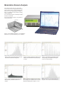
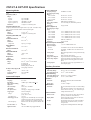
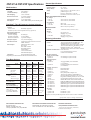
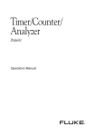
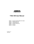
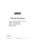
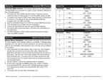
CNT-81 & CNT-81R
product data
Timer/Counter/Calibrators
Ultimate Time & Frequency
calibration & analysis
NOW with
8 GHz option and
TimeView
• Fast: 8000 measurements/s
resolution: 1ps (time)
• High
11 digits/s (freq.), 0.001° (phase)
• Rubidium stability: 0.0001 ppm
• High trigger resolution: 1.25 mV
• Advanced arming/hold-off
• Modulation Domain Analysis SW
for noisy
• EMC-immunity
environments
for fast test systems, R&D
• Ideal
and calibration laboratoires
GHz option for microwave IRF
• 8testing
With the CNT-81 series of counters and analyzers, Pendulum now offers
the ultimate tools for measurement, analysis and calibration of Frequency,
Time Interval or Phase, whether in test systems, on the R&D bench, in the
calibration lab or out in the field (portable calibration). The series comprises 2 models; the ultra-high performance CNT-81 and the ultimate
CNT-81R including a built-in Rubidium time-base reference.
Frequency calibration
Selection Chart
CNT-81
CNT-81R
The CNT-81 and CNT-81R can directly calibrate any application specific frequency up
to 8 GHz. They are ideal for calibrating e.g.
the timebase oscillator of other instruments,
like frequency counters and synthesisers.
The Rubidium timebase of CNT-81R allows frequency calibration of even the highest possible specified oven oscillators. For a
total uncertainty of 10-10, just connect the
unknown frequency to the counters input
and wait for a second.
Each individual 1s-measurement has a
5x10-11 resolution. The built-in statistics averaging improves resolution further, and the
std dev indicator gives added information
about the stability of the unknown frequency.
Frequency, burst, time interval, phase, Vp-p
•
300 MHz
11 digits
50/1 ps
1.25 mV
•
300 MHz
11 digits
50/1 ps
1.25 mV
•
10 ns
-9
3x10
1+0
250/s
8 k/s
•
10 ns
-11
5x10
6+1
250/s
8 k/s
•
•
•
Option 10
Option 13
•
Option 10
Option 13
Time Interval calibration
For the calibration of time-intervals the
CNT-81 provides leading performance due
to the fast 50 ps single shot time resolution
(1 ps averaged) and the high trigger level
resolution of 1.25 mV.
The systematic start-stop channel difference
is only 500 ps, which can be further reduced
by calibrating the input channel difference.
Phase calibration
With CNT-81 you can measure phase differences on signals of up to 160 MHz with a
Frequency range (standard)
Frequency resolution (1s gate time)
Time interval resolution (single/average)
Vp-p (and trigger level) resolution
Arming/Hold-off delay by time and events
Hold-off resolution
Best timebase stability/month
No. of 10 MHz +5 MHz reference outputs
Measurement speed:
GPIB
to internal memory
Statistics calc.: mean, std, dev. and max/min
TimeView Documenting and Analysis SW
2.7 GHz HF-input
8 GHz RF-input
resolution better than 0.01° (below 30
MHz). This gives you outstanding resolution
in measurements like laser positioning and
calibration of phase meters. Calibration procedures exist that provide outstanding accuracy, with an uncertainty below 0.1°.
Ideal for fast test systems
In manufacturing test systems two things are
important; EMC-immunity and speed.
CNT-81 offers excellent EMC-shielding and
the highest throughput for any commercially
available counter. The speed is impressive
8000/s to internal memory, and 250/s for individually triggered measurements via GPIB. Up
to 20 complex measurement set-ups can be locally stored in the counter’s non-volatile set-up
memory and instantly recalled via a short bus
command. This enables new measurement
tasks to be executed one after the other at a
very-high rate. A complete cycle
“setup-measure-transfer” takes less than 8 ms.
The two counters comply of course to SCPI,
which facilitates easy updating of new test
hardware without the penalty of time-consuming SW-rewriting.
Modulation Domain Analysis
The analysis PC-SW TimeView converts the
CNT-81/CNT-81R to a high performance modulation domain analyzer. In the modulation domain you can view rapid frequency changes vs.
time, e.g. modulation, sweep, freqiency setting,
channel hopping etc.
The 16-bit DOS program is standardly included
with all CNT-81/81R.
The 32-bit Windows program is an optional accessory (option 29).
Figure 1: The modulation domain (f vs. t) complements
the time (V vs. t) and the frequency (V vs. f) domains
Figure 2: Jitter (rms and peak-peak) and noise
is quantified in distribution histograms.
Figure 4: Linearity of frequency sweep can be
verified in the modulation domain (frequency
vs. time).
Figure 6: The 9 different pulse width clusters,
corresponding to the 9 different pit lenghts
(T3-T11) in a CD-recording.
Figure 3: The FFT-diagram reveals the modulation frequency, whether intended or unwanted.
Figure 5: Repetitive samplings gives an effective sampling rate of 10 Msa/s. This VCO has a
frequency switching time of approx. 10.7 us.
Figure 7: Zoom in on T3-cluster displays an
rms-jitter of 13 ns, which is OK for an audio CD.
CNT-81 & CNT-81R Specifications
Measuring Modes
Inputs A and B can be swapped internally in all modes except Rise and Fall
Time.
Frequency A, B, C
Range:
Input A:
up to 300 MHz
Input B:
up to 100 MHz
Input C (option 20):
100 MHZ to 2,7 GHz
Input C (option 13):
300 MHz to 8 GHz
Resolution:
11 digits in 1s measuring time
Frequency Burst A, B, C
Frequency and PRF of burst signals down to 1µs (CH. A and B) or 50 µs
(Ch. C) can be measured without external control signals.
Period A
Range:
3.3 ns to 1010s
Resolution:
11 digits in 1s measuring time
Frequency Ratio A/B, C/B
Range:
10-9 to 1015
Time Interval A to B
Range:
0 ns to 1010 s
Resolution:
Single shot:
50 ps (1 ps average)
Pulse Width A
Range:
3 ns to 1010 s
Rise and Fall Time A
Range:
3 ns to 1010s
Phase A Relative B
Range:
-180 to +360°
Resolution:
0,01°
Duty Factor:
Range:
0.000001 to 1.000000
Totalize A, B
Range:
0 to 1017, 0 to 1010 in A-B modes
Modes:
A Gated by B
A Start/Stop by B
Manual gating A minus B
Time gating A minus B
V max, V min, Vp-p A, B
Range:
-50V to + 50V
Frequency Range:
up to 100 MHz
Resolution:
1.25 mV
Inputs and Outputs
Inputs A and B
Coupling:
Impedance:
Max. Channel Timing
Difference:
Max. Sensitivity:
Attenuation:
Var. Hysteresis A:
Triggerpegel:
Range:
Resolution (x1):
AUTO-Trigger Level:
Min. Frequency:
Low Pass Filter A:
Digital LP Filter:
AC or DC
1 MΩ/15 pF or 50Ω/(VSWR<2:1)
500 ps
20 mV rms, <100 MHz
x1or x10
30 mVp-p to 10Vp-p hup to 120 MHz
read-out on display
(x1):-5V to +5V
(x10): -50V to +50V
1.25 mV
Trigger level is automatically set to 50% point
of input signal (10% and 90% for Rise/Fall
Time, 75% and 25% for variable hysteresis A)
Settable from 1 Hz and upwards. Default=100
Hz
100 kHz
1 Hz to 10 MHz using trigger Hold-Off
Input C (Option 20)
Frequency Range:
100 MHz to 2.7 GHz
Operating Input Voltage
Range:
0.1 to 0.3 GHz:
20 mV rms to 12V rms
0.3 to 2.5 GHz:
10 mV rms to 12V rms
2.5 to 2.7 GHz:
20 mV rms to 12V rms
Impedance:
50Ω nominal, (VSWR<2.5:1)
Max Voltage Without
12V rms during 60s, PIN-diode protected
Damage:
Connector:
N-type, female
Input C (Option 13)
Operating input voltage
range:
0.3 to 0.5 GHz
-21 to +30 dBm (20 mV rms to 7V rms)
0.5 to 3.0 GHz
-27 to +30 dBm (10 mV rms to 7V rms)
3.0 to 4.5 GHz
-21 to +30 dBm (20 mV rms to 7V rms)
4.5 to 6.0 GHz
-15 to +30 dBm (40 mV rms to 7V rms)
6.0 to 8.0 GHz
- 9 to +30 dBm (80 mV rms to 7V rms)
Impedance:
50Ω nom, VSWR<2:1
Connector:
N-type, female
Rear Panel Inputs and Outputs
Reference Input:
1, 2, 5 or 10 MHz>200mV rms
Reference Output:
CNT-81:
1x10 MHz>0.5V rms sinewave into 50Ω load
CNT-81R:
6x10 MHz; 1x5 MHz>0.6V rms sinewave into
50Ω load
Arming Input:
Most mesuring functions can be performed using
arming
Gate Output:
Gate open/gate closed signal
Trigger Level Outputs:
Outputs for channel A and B trigger levels
Probe Comp. Outputs:
Outputs for channel A and B to adjust for best
pulse response when using probes for counter
inputs
Analog Output:
0 to 4.98V in 20 mV steps; proportional to 3 selected display digits
Auxiliary Functions
Trigger Hold Off
Time Delay Range:
Event Delay Range B:
External Arming
Time Delay Range B, E:
Event Delay Range B:
Statistics
Functions:
Sample Size:
Mathematics
Functions:
Other Functions
Measure Time:
Display Hold:
Set-ups:
Display:
60 ns to 1.34s, 10 ns resolution
2 to 224-1, max. 100 MHz
200 ns to 1.6s, 100 ns resolution
2 to 224-1, max. 20 MHz
Maximum, Minimum, Mean and Standard
Deviation
1 to 2x10⁻⁹ samples
(K*X+L)/M and (K/X+L)/M, X is urrent reading
and
K, L and M are constants; set via keyboard or as
frozen reference value (Xo) or as value from preceding measurement (Xn-1).
Single cycle, 80, 160, 320, 640, 1280 ns and 20
µs to 20s (to 400s for some functions)
Freezes measuring result, until a new measurement is initiated via Restart.
20 instrument setups can be saved and recalled
from internal non-volatile memory. 10 can be
user protected.
10-digit LCD with high-luminance back-light
CNT-81 & CNT-81R Specifications
General Specifications
GPIB Interface
0°C to 50°C
-40°C to 70°C
CSA 22.2 Nr. 231, EN 61010-1, Cat. II
pollution degree 2, CE
EMC:
EN 5501 1 ISM Group 1, Class B;
EN 50082-2; FCC Part 15J Class A, CE
Power Line Requirements (at 25°C)
AC Voltage:
CNT-81:
90 to 265V rms, 45 to 440 Hz
CNT-81R:
90 to 265V rms, 45 to 440 Hz
Power Rating:
CNT-81:
Max. 35W
CNT-81R:
Max. 100W (6 min. warm-up);
Max. 47W (cont. operation)
Mechanical Data
WxHxD:
315x86x395 mm (12.4x3.4x15.6 in)
Weight:
CNT-81:
Net 4 kg (8.5 lb)
Shipping 7 kg (15 lb)
CNT-81R:
Net 4.8 kg (10.5 lb)
Shipping 7.8 kg (16.8 lb)
Max Measurement Rate*
Via GPIB:
To Internal Memory:
Time Stamping:
Back-to-back-Period:
Internal Memory Size*:
Data Output:
250 readings/s
8k readings/s
125 ns resolution
Up to 40k readings/s
(100 ns resolution)
Up to 6100 readings
ASCII, IEEE double precision floating point
TimeView™ Time & Frequency Analyse Software
TimeView is supported on both CNT-81 and CNT-81R models.
Versions:
DOS-version:
Standardly supported
Windows (32 bit) version: Optional accessory (option 29)
Data Capture Modes and
Measurement Rate*
Free-run sampling:
8k readings/s
Repetitive Sampling:
Up to 10 MSa/s
Back-to-back-Period:
Up to 40k readings/s
Waveform Capture:
Yes (vertical sampling)
Instrument Control:
All front panel functions and some AUX
MENU functions
Data Analysis:
Measurement data vs time
FFT Graph
Root Allan Variance
Smoothing function
Zoom function
Cursor measurements
Distribution Histogram
File Storage:
Setup and Measurement data
* Depending on measurement function and internal data format.
Time Base Options
Model:
CNT-81
CNT-81
CNT-81
CNT-81R
Standard
UCXO
Option 30
OCXO
Option 40
OXCO
Rubidium
<5x10⁻⁷
<5x10⁻⁶
n.s.
<1x10⁻⁸
<7.5x10⁻⁸
n.s.
<3x10⁻⁹
<2x10⁻⁸
n.s.
<5x10-11*
<2x10⁻¹⁰
<1x10⁻⁹
<1x10⁻⁵
<3x10⁻⁶
<5x10⁻⁹
<6x10⁻¹⁰
<2.5x10⁻⁹
<4x10⁻¹⁰
<3x10⁻¹⁰
<2x10-11
Short Term:
τ=1s(Allan Dev.)
n.s
1x10-11
5x10-12
5x10-11
Warm-up Stability:
after warm-up time of:
n.s.
30 min.
<1x10⁻⁸
10 min.
<5x10⁻⁹
10 min.
<4x10⁻¹⁰
10 min.
Total Uncertainty (2 ):
(20°C -26°C)
1 year after calibration
2 years after calibration
<7x10⁻⁶
<1.2x10⁻⁵
<1x10⁻⁷
<2x10⁻⁷
<2.5x10⁻⁸
<5x10⁻⁸
<2.5x10⁻¹⁰
<5x10⁻¹⁰
Option:
Stability:
Ageing:
per month
per year
per 10 years
vs. temp:
0°C-50°C
20°C-26°C (typ.)
* After 1 month of continuous operation.
Environmental Data
Operating Temp:
Storage Temp:
Safety:
Ordering Information
Basic models
CNT-81
CNT-81R
Included with Instrument
RF Input Frequency
Options (CNT-81/81R)*
Option 13:
Option 20:
Time Base Options
(CNT-81)*
Option 30:
Option 40:
Timer/Counter/Analyzer 300 MHz/50 ps, incl.
Standard timebase (5x10⁻⁷/Month) and
Time&Frequency Software TimeView for DOS
Timer/Counter/Calibrator 300 MHz/50 ps, incl.
Rubidium timebase (5x10-11/Month) and
Time&Frequency Software TimeView for DOS
Power line cord
Users documentation on CD-rom
Certificate of Calibration
8.0 GHz Input C (CNT-81/81R)
2.7 GHz Input C (CNT-81/81R)
Very-high stability Oven Time Base
(1x10⁻⁸/Monat)
Ultra-high stability Oven Time Base
(5x10⁻⁹/Month)
Optional Accessories*
Option 11:
Rear Panel Inputs
Option 22:
Rack-Mount Kit
Option 27:
Carrying Case
Option 27H:
Heavy Duty Hard Transport Case
Option 29:
TimeView for Windows 98/2000/XP/NT
OM-81:
Operators Manual (printed) for CNT-81/81R
PM-81:
Programmers Manual (printed) for CNT-81/81R
SM-81:
Service Manual (printed) for CNT-81/81R
NI 778416-01:
GPIB-USB interface from National Instruments
NI 778034-0:
PCMCIA-GPIB interface from National Instruments
NI 778209-0:
GPIB-ENET interface from National Instruments
NI 763061-01:
GPIB cable type X2 (1m) from National Instruments
NI 763061-02:
GPIB cable type X2 (2m) from National Instruments
NI 763061-03:
GPIB cable type X2 (3m) from National Instruments
Warranty
Standard
18 months
Option 95/03
Extended to 3 years
Option 95/05
Extended to 5 years
*Options are factory installed upon order and can not be customer retrofitted.
Specifications subject to change without notice
4031 600 80101 rev. 05 August 2006
US: Pendulum Instruments Inc
International: Pendulum Instruments AB
5811 Racine Street
Oakland, CA 94609-1519, USA
Voice:(510)-428-9488 Fax: (510)-428-9469
PO Box 20020, SE-16102 Bromma, Sweden
Voice: +46 8 598 51057 Fax:+46 8 598 51040
Pendulum Instruments
www.pendulum-instruments.com
- Experts in time & frequency calibration,
measurement and analysis