1
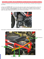
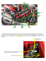
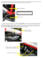
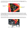
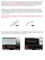
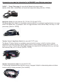
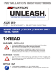
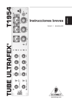
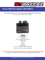
Ducati 848 Streetfighter 2012-2013
Z-Fi QS (Quickshift) / Z-Fi TC (Traction Control) Installation Instructions
Part #s S193S, S193R, T193S, T193R
Parts List:
Z-Fi QS/TC Control Unit
Fuel Harness
Coil Harness
Shift Switch & Mounting Hardware
O2 Eliminator (2)
Scotchlok (2)
Cable Ties
Velcro
USB Cable
Swingarm Stickers
Download Z-Fi Mapper Software at bazzaz.net
Software instructions available at bazzaz.net
USE ONLY IN RACE OR OTHER CLOSED COURSE APPLICATIONS AND NEVER ON PUBLIC ROADS
Z-Fi products are not certified by the California Air Resource Board (CARB) for use on CA highways
Contact Bazzaz tech support at 909-597-8300 for questions
BAZZAZ HARNESS CONNECTOR IDENTIFICATION
Inj 2
Ground
Z-AFM
TPS
Map select
+12V
Switched
Power
Inj 1
Neutral
Main
Speed
CKPS
FUEL HARNESS
Coil 1
Coil 2
Main
Shift
Switch
connector
TC Adjust Switch
connector
COIL HARNESS
Read through all instructions before beginning installation. This is not a replacement for the ECU. This
document is intended for use by qualified technicians. Refer to a factory service manual for more specific
stock component identification and location information.
WE STRONGLY SUGGEST THAT AN EXPERIENCED TECHNICIAN INSTALL THIS BAZZAZ PRODUCT
1. Begin the installation by removing the seat, fuel tank, lower left fairing, and both (left and right) air
box covers.
2. Mount the CONTROL UNIT to the side of the charcoal canister using the supplied Velcro and zip ties.
The charcoal canister can be found on the left side of the bike near the radiator. Connect the main
connector of the Bazzaz FUEL HARNESS to the control unit and begin routing the harness towards the
back of the bike, following along the same path as the factory harness.
Fuel harness routing shown in yellow; stock component identification and location shown for reference.
O2 Eliminator
Coil 1
O2 Eliminator
Coil 2
Injector 2
Injector 1
TPS
Neutral
Speed
RPM
3. Locate the factory neutral sensor, which can be found on the back of the engine, on the right side of
the bike. Pull the sheathing back of the factory neutral sensor lead to expose the black wire. Using the
supplied Scotchlok, crimp onto the exposed black wire and insert the Bazzaz NEUTRAL connector into the
Scotchlok.
Bazzaz neutral
connector
Scotchlok crimped onto the black exposed
wire of the factory neutral sensor
Factory neutral sensor
4. Next, locate the factory speed connectors, found on the
right side of the bike near the oil filler cap and attached to
the bottom of the frame rail. Disconnect the factory speed
connectors and install the Bazzaz SPEED connectors in-line
with the factory connectors.
Bazzaz speed connectors
Factory speed connectors
5. Locate the factory Crank Position Sensor (CKPS) connectors, which can be found above the factory
speed connectors, in front of the rear cylinder and on the right side of the bike. Now disconnect the
factory CKPS connectors and install the Bazzaz CKPS connector in-line with the factory connectors.
Factory CKPS connector
(hidden in photo)
Bazzaz CKPS connectors
Factory CKPS connector
6. Now locate the factory Throttle Position Sensor (TPS)
found on the right side of the bike and on the front throttle
body. Begin to route the Bazzaz TPS lead to the factory TPS
connector. Using the supplied Scotchlok, crimp onto the
orange wire of the factory TPS connector and insert the
Bazzaz TPS connector into the Scotchlok.
TPS
Bazzaz TPS connector
Scotchlok crimped onto the orange wire
of the factory TPS connector
7. Route the injector # 1 connector of the Bazzaz harness up towards the front factory injector, which can
be found on the right side of the bike, near the neck of the frame and the air box.
In order to gain access to the factory injector, the right side air box cover will need to be removed. Once
air box cover is removed, disconnect the factory injector connector from the injector.
Install the Bazzaz INJECTOR CONNECTORS in-line with the factory injector and connector.
Factory injector #1
(hidden in photos)
Factory injector connector
Bazzaz injector #1 connectors
8. Next, locate factory injector # 2, which can be found on top of the air box. Route the Bazzaz injector #
2 connector up to the factory injector. Disconnect the factory injector connector from the injector. Install
the Bazzaz INJECTOR CONNECTORS in-line with the factory injector and connector.
Make sure the routing of the Bazzaz and factory connectors are under the fuel line due to the tank’s tight fit.
Bazzaz injector connectors
Factory injector #2
Factory injector connector
9. Route the Bazzaz GROUND LUG near the same location the Bazzaz control unit is mounted, and install
it to any 8mm bolt on the left side of the bike.
Bazzaz ground
Factory ignition connectors
10. Now, locate the factory ignition connectors, which can
be found behind the left side air box covers. Begin to route
the fuel harness up to the neck of the frame and disconnect
the factory ignition connectors. Install the Bazzaz + 12V
SWITCHED POWER connectors in-line with the factory
ignition connectors.
Bazzaz +12V switched power connectors
11. Locate the rear factory O2 sensor connector which is found above the shock linkage, attached to
the frame. Disconnect the factory O2 sensor connector, as it will no longer be used. The wires should
be neatly secured away from any moving components, or the sensor may be removed and the remaining
port/bung in the exhaust can then be plugged. Connect the Bazzaz O2 ELIMINATOR in place of the factory
sensor connector and attach the O2 eliminator ground lug to a solid ground; the supplied O2 eliminator
must be connected in place of the O2 sensor connector to avoid triggering a fault code (FI light).
Factory rear O2 sensor connector
disconnected and secured away
Bazzaz O2 eliminator
Bazzaz ground is attached on
other side of tank mount
12. Now locate the front factory O2 sensor connector which will be found between the cylinders and can
be accessed from the left side of the bike. Repeat the same process as step 11.
Bazzaz O2 eliminator
Disconnected factory front O2 sensor
connector cannot be seen in photo
Bazzaz ground
13. Connect the main connector of the Bazzaz COIL HARNESS to the control unit and route the harness
along the same path as the fuel harness. Locate the front factory coil connectors, which can be found
attached to the frame, behind a radiator hose. Disconnect the factory coil connectors and install the
Bazzaz # 1 COIL CONNECTORS in-line with the front factory connectors.
Front factory coil
connectors joined
Front factory coil connector
(other connector cannot be seen)
Bazzaz #1 coil connectors
14. Locate the rear factory coil connectors, which can be found attached to the frame, near the rear
cylinder. Disconnect the factory coil connectors and install the Bazzaz # 2 COIL CONNECTORS in-line with
the rear factory connectors.
Rear factory coil
connectors
Bazzaz #2 coil
connectors
15. Now you will begin the installation of the SHIFT SWITCH by removing the factory shift rod. Install
the Bazzaz shift switch onto the heim joint connected to the shift shaft of the engine. Then install the
supplied SHIFT ROD between the shift switch and the rear heim joint connected to the rear set. Bazzaz
shift rods are manufactured to fit multiple applications and can be cut at 10mm intervals on either end to
shorten for proper positioning.
Adjust the foot pedal to preferred height and secure components by tightening the 10mm nuts. Now
route the shift switch connector up to the mating connector of the Bazzaz coil harness and plug in-line.
To complete the installation, use the supplied cable ties to secure the harnesses neatly along the routing
path free of any moving or hot components (which could cause damage or failure of the system). If any
problem is found, please carefully follow through the installation steps again. If problem still persists,
please call Bazzaz tech support at (909) 597-8300. After it is determined that everything is correct,
reinstall the components removed in step one and the installation will be complete.
The Bazzaz control unit is capable of storing two maps. These maps can be selected by connecting or
disconnecting the map select jumper on the fuel harness (or you can switch maps on the fly with the
handle bar mounted map select switch, sold separately). When the map select jumper is connected, the
control unit is operating using map 1. When the map select jumper is disconnected, the control unit is
operating using map 2.
The control unit is pre-programmed from the factory with an enhanced map in the map 1 position. The
map 2 position is using the stock ECU map. You are able to load and unload maps as needed via the Z-Fi
Mapper software.
Map 1
Map 2
Don’t forget to download the Z-Fi Mapper software from www.bazzaz.net (under the software tab) so that you can
adjust your fuel map, QS or TC settings (depending on the product you purchased). You will also need access to the
Z-Fi Mapper software if you will be using the Z-AFM self-mapping kit.
Accessories you may be interested in to ENHANCE your Bazzaz experience
Z-AFM™ | Tuning Technology (for use with all Bazzaz fuel control units)
Quickly collect data to build ideal, self-made fuel maps while riding. [Part No. 127062]
Map Select Switch (for use with the Z-Fi, Z-Fi MX, Z-Fi QS and Z-Fi TC)
The Bazzaz Map Select Switch is a handlebar-mounted switch for convenient toggling between two maps
held on the Bazzaz unit. For example, rider can toggle between a fuel efficient map, rain map, or a full
power map. [Part No. 127078]
Traction Control / Map Select Switch (for use with Z-Fi TC only)
The Bazzaz TC Adjust Switch is a handlebar-mounted switch for easy, on the fly, traction control
adjustments and map switching. Quickly adjust traction control settings (a great way to learn TC), or
switch off, using a 10-point dial. Also toggle between two maps held on the Bazzaz unit (e.g. rain map,
fuel economy map, etc.) on the fly. [Part No. 127079]
Traction Control Active Light (for use with Z-Fi TC)
TC Active Light illuminates when traction control is engaged. Helpful in determining when and where
traction control is being actuated. [Part No.M842]