1
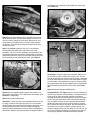
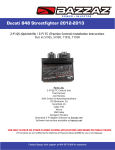
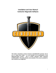
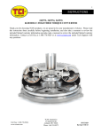
151 INDUSTRIAL DRIVE
ASHLAND, MISSISSIPPI 38603
http://www.tciauto.com
TELEPHONE: 662-224-8972
FAX LINE: 662-224-8255
E-MAIL: [email protected]
TCI® 386000 Trans-Scat® Kit
Installation Instructions for Turbo 2004R — 1981-1991
This kit will allow you to modify your 2004R transmission for
your particular driving requirements.
Street Plus: This type of modification is the modifications
TCI® used when building a StreetFighter® transmission. The
shift feel is very positive and sharp.
Heavy Duty: This type of modification is used for towing,
campers, motor homes, police, taxi and other vehicles that put
a lot of stress on the transmission. The shift is firm but not
harsh.
NOTE: This kit is not intended for installation in a transmission
in poor general condition. It will not correct a malfunctioning or
slipping transmission.
This Kit Contains:
Qty.
Description
One (1) Separator Plate
Two (2) Gaskets: One (1) Valve Body (marked VB or V)
One (1) Case Gasket (marked C)
One (1) 1-2 Accumulator Plate Gasket
One (1) Transmission Pan Gasket
One (1) Purple Pressure Regulator Spring
One (1) Tan Line Bias Spring
One (1) Line Bias Blocker Rod
One (1) Filter seal
Step 3 There are several different wiring arrangements that
are found in the 2004R transmission valve body. Different
engine sizes and emission standards dictate what wiring
was needed for your particular application. Before you
remove any wires or switches, take time to draw your own
diagram of the location of your valve body wiring, terminal
locations and connections. Some of the wiring is held in
place by a retaining clip that is connected by valve body
bolts. Remove these bolts first to remove wiring harness.
Remove the converter clutch solenoid. The wiring harness
does not have to be completely removed from transmission;
just remove from the valve body area. You can let the
harness hang loose since you are working only with the
valve body.
Step 4 Remove the throttle lever and bracket assembly.
Assembly is located near the torque converter clutch
solenoid and is held in place with one bolt. Disconnect TV
cable link from bracket assembly. (See Photo 1) If your
transmission has a lifter wire and spring assembly (in area
indicated by arrow), it may be discarded as it will not be
reused.
Step 1 Drain transmission oil pan. You will need a pan to catch
fluid. Remove transmission oil pan bolts. When removing bolts,
remove so pan will not drop completely off but will be held in
place so that one side will allow the fluid to be drained. After
the fluid has drained, remove the rest of the bolts and pour out
the remaining fluid. Turbo 2004R transmissions do not have a
drain plug. You may want to install a TCI® 805800 universal
drain plug kit into your pan now that you have the pan off the
transmission.
Step 2 Carefully remove the oil filter by pulling it straight down.
Remove the pickup tube O-rings from the pump if they do not
come out with the filter. Double check! Many transmissions
came from the factory with two (2) O-rings on the filter. Inspect
the oil filter. Replace the filter if it is dirty or has not been
changed in over 25,000 miles. TCI® 386850 filter will fit this
application, if needed.
TV Cable Link
Photo 1
Step 5 Remove detent roller and tube bracket. Assembly is
held in place with one bolt. (See Photo 2)
Reassemble valve assembly and reinstall into valve body.
(See Photo 5A)
Photo 2
Step 6 Remove all remaining valve body bolts. Remove the
center bolt last. After you have removed all but this one bolt,
use your hand to steady the valve body. Remove bolt, and
slowly lower valve body housing. The valve body contains
check balls. This will help you keep the check balls in place
not lose any parts.
Step 7 (See Photo 3) Remove four (4) 1-2 accumulator
housing bolts (indicated by the stars) and remove the
assembly. You must remove remaining bolt (indicated by the
triangle) that holds the accumulator spacer plate to separator
plate. When this bolt is removed, lower plate making sure that
the check balls are not lost during removal. (See Photo 3)
Photo 4
Replace spring
with blocker
rod
A
Photo 5
Replace
with TCI®
line bias
spring
B
Heavy Duty: Locate line bias valve assembly. Remove roll
pin by using a scribe or heavy wire to push it out. The line
bias valve assembly has a spring that will push the assembly
out of the bore when the roll pin is removed. Make sure that
you catch hold of the assembly and remove. Remove OEM
spring and replace with spring supplied with kit. Reassemble
valve assembly and reinstall into valve body. (See Photo
5B)
Photo 3
Step 10 Pressure Regulator Modifications:
Step 8 After the separator plate has been removed the 3-4
accumulator may drop out. No modifications are needed. (See
Photo 4 for reassembly)
All Applications: (See Figure 1) Note: It is not necessary to
remove the pump from the transmission. The figure shows a
loose pump for clarity purposes. Remove the pressure
regulator assembly from the transmission pump. Push down
on the TV boost valve sleeve while removing the retaining
ring. Be careful, as there is heavy spring tension behind it.
Slowly lower the sleeve to relieve spring tension. Remove
the TV boost valve sleeve and valve, the low/reverse boost
sleeve and valve, and the pressure regulator spring. The
pressure regulator valve may also drop out. If it does not, do
not remove. Replace the pressure regulator spring with the
purple spring supplied. Reinstall the pressure regulator
Step 9 Valve Body Modifications:
Street Plus: Locate line bias valve assembly. Remove roll pin
by using a scribe or heavy wire to push it out. The line bias
valve assembly has a spring that will push the assembly out of
the bore when the roll pin is removed. Make sure that you
catch hold of the assembly and remove. Remove OEM spring
and discard. Replace spring with blocker rod supplied with kit.
assembly with the new spring as shown. Install the retaining
ring making sure that it’s fully seated in the groove.
Heavy Duty: Match the separator plate supplied with this kit
with your OEM plate. You will need to drill two (2) new holes.
Drill the converter relief hole and the 1-2 accumulator hole.
Drill the accumulator hole to 3/16" in the TCI® plate. Deburr
and wash plate. (See Photo 7)
All Applications:
Converter Clutch
Hole
Heavy Duty:
1-2 Accumulator
Hole
Figure 1
NOTE: The boost valves and low/reverse boost valves can
easily be installed incorrectly. Incorrect assembly will cause
the transmission to function improperly. BE SURE these parts
are installed in the correct order, facing the right direction. The
TV boost valve and sleeve may be replaced with a 0.500"
diameter TCI® 374301 or a 0.570” diameter TCI® 374401
assembly to further increase pressures. Additionally, for more
pressure in manual first and second gears replace your
low/reverse boost valve with a 0.400” diameter TCI® 374410.
Step 11 Servo Modifications: Locate the servo on the
passenger side of the transmission case. Since, the
transmission has not been removed from the vehicle, you may
have to remove and reinstall the catalytic converter before you
can get to the servo. Remove the snap ring holding the servo
cover in place. Remove cover and servo assembly from case.
Remove and discard small servo spring. Remove Teflon® ring
and discard from inner piston assembly. (See Photo 6) Now
you are ready to reinstall servo assembly.
1
1
2
3
4
5
6
7
7
3
4 5
2
6
Servo Return Spring – DISCARD
Servo Apply Pin
Servo Spring Retainer
Servo Cushion Spring
Inner Piston – DISCARD SEALING RING
Outer Piston
Servo Cover
Photo 7
Step 13 Check Ball Locations in Case:
Street Plus: Install check balls in case as indicated. (See
Photo 8) You may use grease to hold check balls in place.
Install four (4) check balls only. You will not be using three
(3) remaining check balls, just discard.
Heavy Duty: Install check balls in case as indicated. (See
Photo 8) You may use grease to hold check balls in place.
Install five (5) check balls in the case. You will not be using
the two (2) remaining check balls, just discard.
1 2
3
4
5 Heavy Duty Only
Photo 8
Photo 6
Step 14 1-2 Accumulator Modifications:
Step 12 Separator Plate Modifications: (See Photo 7)
Street Plus: Do not reinstall 1-2 accumulator piston and
spring.
Street Plus: The separator plate supplied with this kit will need
to have one hole drilled. Match your OEM plate with the TCI®
plate and mark location of torque converter clutch hole. Size
the hole in your OEM plate and drill TCI® plate to same
diameter. Deburr and wash plate.
Heavy Duty: Reinstall complete 1-2 accumulator piston and
spring assembly.
Install case-side separator plate gasket, separator plate, valve
body-side gasket and accumulator spacer plate. Note that the
gaskets are stamped at the top with a ‘C’ for case and ‘VB’ for
valve body side. Use the small bolt to hold the accumulator
housing plate in place. (See Photo 3) Next install accumulator
housing. Use the four (4) 1-2 accumulator bolts.
Step 15 Check Ball Location in Valve Body:
Street Plus and Heavy Duty: Install one (1) check ball and
discard remaining two (2) check balls. (See Photo 9)
Step 20 Adjustment of the Throttle Valve Cable in a
Gasoline Engine. Adjustment is made with engine not
running.
Locate the readjust tab. Depress tab and move slider
through the fitting away for the lever assembly. When the
slider stops against the fitting, release readjust tab.
By hand, open the throttle lever to full or wide open throttle
stop position. This will automatically adjust cable. Release
the throttle lever and check the cable to see that it is not
binding or sticking. REMEMBER, DO NOT USE
ACCELERATOR PEDAL TO ROTATE THE THROTTLE
LEVER. YOU MUST ROTATE BY HAND AT THE
CARBURETOR.
Step 21 Now that the adjustment is complete, road test. With
moderate acceleration your transmission should shift:
1st gear ………………15-20 MPH
2nd gear………………25-30 MPH
3rd gear………………40-45 MPH
Photo 9
Step 16 Reinstalling Valve Body to Transmission Case:
When installing valve body you must connect manual valve to
transmission linkage. (See Photo 10)
If the Throttle Valve Cable is not adjusted properly the
transmission will shift into 1st, 2nd and 3rd within seconds of
acceleration. DO NOT CONTINUE TO DRIVE VEHICLE IF
THIS HAPPENS. Readjust cable. If you continue to have
problems, please contact TCI®’s tech department for
assistance.
WARNING! IMPORTANT NOTICE!
AFTER INSTALLATION ADJUSTMENT.
It is imperative that after your new 2004R transmission has
been installed that the Throttle Valve Cable (TV Cable) has
been adjusted properly. If this adjustment has not been
made properly, DAMAGE will occur to the transmission,
voiding warranty. If you are unsure about the proper
adjustment needed call our tech line for help or refer to a
Motors or Service manual for additional information and
reference.
Function of Throttle Valve Cable: Many people believe
that this is an automatic downshift cable and that is the only
function of this cable. In actuality, the Throttle Valve Cable
controls line pressures, shift points, shift feel, part throttle
downshifts and detent downshifts. The cable is very similar
to the functions of both a vacuum modulator and detent
downshift cable in other transmissions.
Photo 10
Step 17 After the valve body has been reassembled, torque,
the valve body bolts to 10 foot pounds.
Throttle Valve Cable Connections: The transmission valve
body is linked to the throttle lever and bracket assembly and
from there the TV Cable is linked to the carburetor or
injection of the vehicle. Between the carburetor and
transmission a TV cable adjustment is used to set proper
adjustment.
Step 18 Complete reassembly.
Step 19 Fill transmission to proper fluid level. Since the
converter is already full, the transmission will need
approximately 6 quarts of fluid. Do not over fill transmission.
TCI® recommends the use of our RTF transmission fluid that
is formulated for heat reduction and high stress applications.
4/13/04